EP0614644B1 - Automatic mop device - Google Patents
Automatic mop device Download PDFInfo
- Publication number
- EP0614644B1 EP0614644B1 EP94500047A EP94500047A EP0614644B1 EP 0614644 B1 EP0614644 B1 EP 0614644B1 EP 94500047 A EP94500047 A EP 94500047A EP 94500047 A EP94500047 A EP 94500047A EP 0614644 B1 EP0614644 B1 EP 0614644B1
- Authority
- EP
- European Patent Office
- Prior art keywords
- mop
- squeezing
- casing
- switch
- bucket
- Prior art date
- Legal status (The legal status is an assumption and is not a legal conclusion. Google has not performed a legal analysis and makes no representation as to the accuracy of the status listed.)
- Expired - Lifetime
Links
Images


Classifications
-
- A—HUMAN NECESSITIES
- A47—FURNITURE; DOMESTIC ARTICLES OR APPLIANCES; COFFEE MILLS; SPICE MILLS; SUCTION CLEANERS IN GENERAL
- A47L—DOMESTIC WASHING OR CLEANING; SUCTION CLEANERS IN GENERAL
- A47L13/00—Implements for cleaning floors, carpets, furniture, walls, or wall coverings
- A47L13/10—Scrubbing; Scouring; Cleaning; Polishing
- A47L13/50—Auxiliary implements
- A47L13/58—Wringers for scouring pads, mops, or the like, combined with buckets
Definitions
- the present specification refers to an automatic mop device for cleaning floors, the purpose of which is to help an user to clean a surface such as a floor, by substantially reducing the own user's effort as it makes easy to squeeze dry a mop or the fringes of a mop, located at the lower end of a supporting stick, such as a broomstick.
- This invention applies to the industry devoted to the manufacture of industrial and domestic appliances.
- All these sticks had, at one end, a receiving body, at first, formed by a duster or floorcloth, which, incorporated and bonded in its surface, carried out a cleaning operation, said surface having been previously wetted thanks to the optional cooperation of a cleaning product or detergent.
- the user After the first cleaning operation by wetting the surface to be cleaned, the user should remove the duster or floorcloth, squeze it dry, and locate it on the corresponding portion of the stick situated at one of its ends in order to perform the drying operation of the previously water - wetted surface in cooperation with a cleaning product or not.
- parts made of a light material have been incorporated in the ends of a stick, said parts having a plurality of filiform elements securely united, made of a textile material being capable of receiving a large amount of water and transferring it to the surface to be cleaned, these devices being known as mops or scrubbers.
- the mop or scrubber was squeezed dry to remove the water carried by it, and then it was necessary to carry out a second operation in order to remove the water from the already cleaned surface.
- the user In order to perform the squeezing operation, the user must insert the assembly of textile material elements within a body having a reverse truncated cone shape having a plurality of perforations allowing the water to pass inside a carrier bucket, and then to twist the assembly for carrying out the squeezing operation, which, after a certain period of time, causes user's arm and back aches.
- a squeezing device configured starting from a body adaptable to the mouth of a bucket having a quadrangular or rectangular plan, is protected and claimed, which receives, after the squeezing operation,the water from this operation, and, at the same time, it uses thiswater for the cleaning operations following the mop squeezing, the body being constituted as a frame or casing, in the interior of which there are a plurality of gears, the function of which is to bond, join or unite two cylindrical bodies arranged in a transverse mode, after an user has operated an external lever, this lever acting as a starting element in a fully manual operation of the different internal mechanisms which, with their motion and turning, manage to gradually free the mop of scrubber from the water incorporated in its structure.
- this mechanism acting as a squeezer for a conventional scrubber, combines particular characteristics simplifying the own squeezing operations, requires, on the user's side, to perform a marginal effort to put into operation the squeezing mechanism, by operating the lever; these operations requiring, - even reducing the effort, in a specific manner, to make an effort for operating the rollers.
- This invention applied for in USA, is to be incorporated in a markedly rigid supporting body, fitted inside with a large hollow space for receiving the removed water, relying on its surface on an emerging body having a cylindrical configuration, fitted, at its upper part , with an access mouth, on which the mop or scrubber is joined, and presenting at the lower part a slot aligned with the center zone existing between the squeezing cylinders, which are driven by a motor externally arranged, which, in turn, is connected to the mains.
- the invention is driven by motive elements externally connected to a motor, this motor being fitted with an external circular crown which acts on a chain moving at least one of the rollers, so that, in cooperation with a filiform body inserted between both rollers, both cylinders, in parallel alignment move, the other roller having springs which sustematically push the stationary roller with the movable roller, so obtaining in consequence the squeezing operation, the apparatus being inexcusably connected, for feeding and driving the motor, to the - mains, which implies a potential danger, since the element to be squeezed is still wet, and although the motor casing is properly shielded and insulated, any anomaly can cause en electric shock to the user.
- This invention is qualified to start the motor when the mop or scrubber contacts a sensor located on the access ramp toward the rollers.
- the patent of invention applied for in USA under number 4.344.201 discloses a mop or scrubber capable of being squeezed thanks to the existence of a squeezing body arranged on a bucket or similar receptable, and having, at the lower side, a motor fed by electric power connected thru a cable and pin to a conventional mains, so moving a shaft joined to a hollow truncated cone fitted with a plurality of drillings inside, the turning of the shaft generating the removal of the water carried by the mop or scrubber.
- a suitable solution would be to rely on the existence of an apparatus that, configured like a scrubber in the strict sense, could allow the water carried by the fringes of a mop or scrubber to be removed, the squeezing operation being carried out in a simplified manner, starting from the use of a motor automatically driving the direct acting elements on the flanges, but, at the same time, reducing the operating times according to the direct applications on the own fringes constituting the cleaning area of the surfaces, this operation being implemented by the actuation, on the active elements, of a motor which, fed by electric power does not present any problems of potential accidents.
- the improved automatic mop device for cleaning floors as proposed by the invention is constituted per se as an evident novelty in the frame in which it is incorporated, and it can be considered as a solution to the squeezing problem of a body made of trips in a textile material used for cleaning and later drying a surface.
- the improved automatic mop device for cleaning floors is constituted starting from a stiff platform provided with wheels facilitating its displacement, a portion of this platform being destined to incorporate in it a mop bucket, and, also placing on the upper portion of the platform and,specifically, where the bucket is situated, a hinged arm.
- a handle On the upper side, a handle has been provided, the function of which is to make easy the device transport, and, at the same time, and owing to the existence of a polarity reversal switch located at one end thereof, an electric circuit is made, enabling a 12V motor which is fed by a direct current, the making of the circuit being attained when performing the operation of squeezing the textile fringes.
- This motor drives a series of speed demultiplying gears, and, at the same time, a power mutiplier, so obtaining both the speed and power which are necessary for operating a series of vanes - squeezing the water carried by the mop body textile fringes.
- the electric feed of the motor for operating said vanes is obtained from a battery located on an adequate frame situated above the wheels carrying the frame and bucket. Said battery can be charged directly from the electric network by means of a portable battery charger.
- the electric motor is specifically designed for limiting its operation for a short period of time, during which said vanes - perform the fringe squeezing, the limiter being configurated as an end of stroke switch which reverses the polarity to the motor, so shifting its turning sense.
- vanes when the vanes recover their rest position, they are ready to start again the squeezing operation of the fringes so many times as required, by means of the person performing the cleaning operation upon pressing the switch located at the mop stick.
- the invention features a main switch connecting and disconnecting the current intake to the motor, and it avoids, consequently, the vanes to act, having a 12V battery and relying on a 15 amp fuse in order to prevent overvoltages.
- the end of the main switch and the end of the fuse are connected with the switch located at the handle, the end of which is - linked, in turn, by connection, to the end-of-stroke switch, limiting the course of motion of the motor driving the squeezing vanes.
- the motor is given a possible direct current in a sense, during which the vanes move and squeeze, but, nevertheless, during the rest time, the motor receives the current in a reverse sense, only the time necassry for allowing the squeezing vanes to move back until recovering their rest position.
- This rest position recovery being performed in a very smooth way in order not to damage the gears moving them.
- the 12V battery, the switch and the fuse are mounted in series.
- the mop device can be shaped starting from a conventional bucket fitted with a squeezing area and on which, a squeezing head is located, this head being fitted with adequate vanes driven by an electric motor that, in cooperation with gears, fuses, battery and switches, drives the vane after pressing a push-button that, linked with the switch, moves said vanes in accordance with the pressing performed by the mop stick, with no need for the mop's user to directly press the push-button as by simply pressing down the latter, the squeezing vanes are set in motion.
- the mop device can be fitted with a press squeezing system driven by two asymmetrical arms located on either side of their inner area, being incorporated inside the frame fitted with adequate characteristics to be located on the upper side of a bucket, two motors which are automatically driven by the own user by simply pressing down a push-button starting said motors and, consequently, the squeezing arms.
- the mop device can be fitted with a magnet to be located in an appropiate area of the mop stick or handle. Said magnet sets automatically the squeezing vanes in motion when it approaches the contact point next to the squeezing basket.
- a base 2 preferably made of a stiff material, configured as a platform having wheels at the bottom side thereof 3, the function of these wheels being to make easy the assembly transport.
- a casing 15 housing a motor, mechanisms and feeding battery of the own motor, while on the other side of the casting, a conventional mop bucket 4 is mounted.
- the mop device 1 has a hinged arm 7 with a joint point 16, a handle 13 and a sliding tube 8 located next the handle or holder 13.
- the casing is fastened to the frame or base 2 by means of conventional screws 11.
- the casing has a connection intake 10 for receiving the cable of a charger from which the 12V battery is charged. This battery is located within the casing, thru which the motor is fed.
- this side of the casing has an intake and connection 12 for a 15 amp fuseholder, and also a switch 14 for starting the mop.
- an arm 5 is installed at the lower middle part of which a squeezing element 9 is located, formed as squeezing vanes. which is inserted into a cavity existing in the upper side of a bucket 4, to be used as a squeezing element of the scrubber or mop fringes.
- the arm 5, specifically in its external upper zone, has a support 6 to which the mop stick is fixed.
- the motor drives an assembly of speed demultiplying gears,and, in turn, a power multiplier, so obtaining the adequate speed and power necessary to said arm or vanes 9 for squeezing the mop fringes.
- the motor is fitted with an end-of-stroke acting thru a small notch that opens, and when the end-of-stroke is effected, it reverses the polarity to the motor, thereby the arm 9 returns to its - rest position. Then, the squeezing operation is started again so many times as required.
- the end-of-stroke switcj limits the course of the motor driving the squeezing arm.
- FIGS 3, 4 and 5 show different views of a second embodiment of the invention, referred, in general, as 20, which is constituted starting from a bucket 22 made of any material, situated on the upper surface of a support and translation part 23 fitted with free turning wheels 24, the bucket 22 having a handle or holder - 26, knurled at its center position to make easy its grasping and adherence to the user's hand.
- a second embodiment of the invention referred, in general, as 20, which is constituted starting from a bucket 22 made of any material, situated on the upper surface of a support and translation part 23 fitted with free turning wheels 24, the bucket 22 having a handle or holder - 26, knurled at its center position to make easy its grasping and adherence to the user's hand.
- a squeezing head 25 is mounted on the bucket 22 by conventional means, which is formed by a casing housing an electric motor, a shaft, gears, a battery and a relay (not shown in the figure, as they are conventional elements, coupled one other in order to achieve the purpose of driving squeezing vanes), the function of the motor being to receive the battery or accumulator current after an external switch 29, located within a notch 28 having a semicircular arc shape, vertically situated, is pressed by the handle or holder of the mop with a ligtht pressure, a relay acting once the switch 29 has been operated, giving the appropiate orders to the inside of the squeezing head with the purpose of causing the motor to act, starting to turn, and setting in motion a shaft acting on the squeezing arms or vanes 27, exerting a pressure on the mop or scrubber located within the basket acting as a filter 30, squeezing the content of water from the mop, this water passing inside the bucket 22, the dirtiness potentially
- the shaft acting in cooperation with the gears due to the fact that it is fitted with a notch acting as end-of-stroke, stops the motion of the squeezing arms or vanes 27, and the presioning operation on the mop by means of the squeezing vanes or arms 27 can be repeated upon acting again on the switch 29, turning the motor fed by an electric current obtained from the battery or accumulator, and commencing again the cycle.
- the bucket 22 has, on its upper edge, a diametrical trimming stiffing it in order to allow a coupling of the squeezing head 25.
- the squeezing head 25 has, in its external portion, exactly on one of its sides, a light pilot 34, showing every moment that the battery or accumulator incorporated inside the squeezing head 25 is being charged by means of an electric current intake configurated as a flexible cable having, at one of its ends, a female pin incorporated in the intake 35, while the other end of the cable has a male pin connected to a conventional electric power intake.
- the squeezing head 25 has a pilot 31 to be lighted on when the lighting switch 32 has been actuated, this switch allowing - that, by operating the grasping element or handle which carries the mop, exactly by the pressure exerted by the user and through the stick on the switch 29, the arms 27 act, squeezing the water carried by the mop and dropping within the bucket 22 thru the bascket or filter 30.
- the squeezing head 25 can be removed from its operational housing, and once the bucket 22 has been duly cleaned up, the squeezing head 25 can be housed within the bucket 22, occupying a minimal space.
- Figures 6 and 7 show a third embodiment of the invention, which has been referenced in a general way with 40, and being constituted starting from a casing or frame 42, on which all the acting mechanisms of the object of the invention are placed, and this assembly of frame or similar 42 being placed on a conventional bucket 43 by using anchoring links 59 located on the back - side thereof, and having lateral projections emerging from steps 60 formed or located at the lower part of the main part.
- the frame or casing 42 is located on a bucket 43, and this, in turn, is placed on a transport carriage 44 fitted with appropiate wheels 45, and it can optionally carry a basket 47 to contain auxiliary elements for cleaning purposes, such as a spare mop, the basket being installed on the vertical arms of handle 46, which facilitates the motion of the assembly composed of a bucket carrying the squeezer on its upper mouth and fixed to one of its - side branches.
- the squeezer has a retaining link for the mop holder 48, fixed to a front area, presenting a center recesss on the upper portion 50, fitted with a switch thru which and with the assistance of the mop o scrubber stick, a light pressure is exerted on said switch,setting automatically in motion the motors in a sense or other, according to the turning of the current obtained from the battery and being determined by a relay driven by said switch 50, and thanks to the cooperation of an end-of-stroke switch (non referenced).
- the motor When the operating switch 50 is enabled, that is to say, when it is subject to the tool and handle or holder of the mop or scrubber pressure, the motor will run in the desired sense, moving the gear assemblies and these latter, in turn, will move the arms 51 and 52, performing the pressing or squeezing operation, so achieving that the arms 51 and 52, when approaching one other, squeeze the mop or scrubber, the water falling towards the lower zone, - passing thru a grating 49, which collects the refuse of the materials caught by the mop, and the water, now practically clean, pass into the bucket 43 on which the assemby is installed.
- the invention relais on a lighting - pilot 54, a main switch 55 and a rapid access protection relay - 56, located on one of the back sides of frame 42, while on the opposite side, a charge indicator pilot 57 is installed, which acts as an indicator for the electric power fed by the battery (not - shown) through a conventional cable 53 plugged in a plug located at the squeezer, and having the other end connected to a conventional socket linked to the electric network.
- the side vanes of support 60 located at the lower part of the frame or casing 42, can optionally have two emerging stubs 58 to be duly engaged on the side walls of bucket 43, exactly on the upper inner zone thereof.
- a fourth embodiment of the invention is illustrated, with general reference 70, which is constituted, as in previous - cases, starting from a bucket 71 made of an appropiate material having a plantar rectangular shape and having all its vertices rounded, presenting, at its upper portion, a perimetral oversized edge acting as a reinforcement link of the own bucket 71, allowing-to fix on same a body 74, inside which all acting elements of the - object of the invention are incorporated.
- the bucket 71 has a handle or holder 75 and it is situated on a platform 72 provided with free turning wheels 73 to make easy its transportation and avoid the user to carry out efforts during the cleaning operations.
- a body containing mechanical and electric elements 74 is installed, having a basket 79 presenting a plurality of perforations in order to allow to pass the water taken out from the mop or scrubber, the main body 79 having a reverse truncated cone shape and with inner vanes 76 acting to perform the mop or scrubber squeezing, these vanes 76 being moved by the motor located in the frame or casing shaping the body 74.
- a pilot light 80 On the upper portion of the main body 74, frame or casing, a pilot light 80. a main switch 81, a fuse holder 82, an indicator 83 are arranged, the function of said indicator 83 being to inform the user about the necessity of recharge the battery located inside, by engaging a feeder in the base of socket 84.
- the automatic mop device by means of the vanes 76 emerging from the inner walls of basket 79, squeezes the fringes - emerging from the mop stick (shown in Fig. 9 with no reference), the vanes 76 exerting an adequate pressure to attain a full squeezing of same.
Abstract
Description
- The present specification refers to an automatic mop device for cleaning floors, the purpose of which is to help an user to clean a surface such as a floor, by substantially reducing the own user's effort as it makes easy to squeeze dry a mop or the fringes of a mop, located at the lower end of a supporting stick, such as a broomstick.
- This invention applies to the industry devoted to the manufacture of industrial and domestic appliances.
- It is known a large variety of elongated cylindrical shaped bodies having, or not, non-slipping areas on their surface in order to facilitate their use, since the function of these areas is to avoid the stick to slide out of an user's hands, and these sticks are made of wood, wood coated with a plastic film, stiff plastic material, lightened metal, and so on.
- All these sticks had, at one end, a receiving body, at first, formed by a duster or floorcloth, which, incorporated and bonded in its surface, carried out a cleaning operation, said surface having been previously wetted thanks to the optional cooperation of a cleaning product or detergent.
- After the first cleaning operation by wetting the surface to be cleaned, the user should remove the duster or floorcloth, squeze it dry, and locate it on the corresponding portion of the stick situated at one of its ends in order to perform the drying operation of the previously water-wetted surface in cooperation with a cleaning product or not.
- In a most recent date, parts made of a light material have been incorporated in the ends of a stick, said parts having a plurality of filiform elements securely united, made of a textile material being capable of receiving a large amount of water and transferring it to the surface to be cleaned, these devices being known as mops or scrubbers.
- Subsequent to the first cleaning operation aided by a large amount of water used for performing the surface cleaning, the mop or scrubber was squeezed dry to remove the water carried by it, and then it was necessary to carry out a second operation in order to remove the water from the already cleaned surface.
- Of course, appreciable novelties have been incorporated in these elements mounted on the stick ends, as for the material, giving them a greater wear resistance, a large amount of water content and, consequently, a higher drying capacity, giving them different shapes, but always having the common denominator of being made starting from a textile material, the main bodies - being formed as a plurality of markedly elongated trips.
- It has been shown that the industrial and domestic cleaning operations involve, in all cases, a remarkable effort which has been lessened by the incorporation, within the cleaning field, of these sticks that, with the cooperation of a mop or scrubber, achieve a remarkable lessening of efforts and, also, avoid the persons performing a flooring operation to carry out this operation in a position which implies an ardous work, such as, for example, kneeling.
- At present, nevertheless, in operations carried out to clean a surface starting from a stick and a scrubber mounted on it, the most significant hard work is to squeeze the mop or scrubber dried.
- In order to perform the squeezing operation, the user must insert the assembly of textile material elements within a body having a reverse truncated cone shape having a plurality of perforations allowing the water to pass inside a carrier bucket, and then to twist the assembly for carrying out the squeezing operation, which, after a certain period of time, causes user's arm and back aches.
- An obvious solution to the present problem would be to rely on a device, machine or apparatus capable of making easy the squeezing operation of the body former by markedly elongated textile materials, so acting like an automatic mop.
- The applicant knows the existence at present of a plurality of patents of invention claiming scrubbers generally applicable to carry out industrial cleanings, in which squeezing devices have been provided that, with the cooperation of a manual actuating lever, achieve two bodies to join one other, obtaining in consequence of this union, a sliding, or by a turn, that the mop or scrubber, constituted by elongated bodies of a textile nature, will be squeezed.
- The applicant knows,also, the existence at present of an European patent applied for under number 0 468 158, in which a squeezing device, configured starting from a body adaptable to the mouth of a bucket having a quadrangular or rectangular plan, is protected and claimed, which receives, after the squeezing operation,the water from this operation, and, at the same time, it uses thiswater for the cleaning operations following the mop squeezing, the body being constituted as a frame or casing, in the interior of which there are a plurality of gears, the function of which is to bond, join or unite two cylindrical bodies arranged in a transverse mode, after an user has operated an external lever, this lever acting as a starting element in a fully manual operation of the different internal mechanisms which, with their motion and turning, manage to gradually free the mop of scrubber from the water incorporated in its structure.
- Obviously, although this mechanism, acting as a squeezer for a conventional scrubber, combines particular characteristics simplifying the own squeezing operations, requires, on the user's side, to perform a marginal effort to put into operation the squeezing mechanism, by operating the lever; these operations requiring, - even reducing the effort, in a specific manner, to make an effort for operating the rollers.
- From the patent of invention applied for in USA under number 3.987.513, it is known the existence of a aqueezing mechanism for mops or scrubbers, which joined to the end of a stick or similar, using a body supporting part made of a textile material, allows two electrically driven rollers, aligned in a transverse and parallel position, to gradually move so that, in a continuous way, the end of the body constituting the scrubber, as for the textile material, inserts in the space existing between both rollers, generating, in consequence, the removal of the water carried, so requiring, after the squeezing operation, a reverse operation of the rollers in order to make also easy to gradually remove the filiform material constituting the end of the scrubber, so obtaining that, after the removal of same, the mop or sceubber may be used for carrying out the corresponding drying of the surface already cleaned, by using water in cooperation with a detergent, - soap or any cleaning product.
- This invention, applied for in USA, is to be incorporated in a markedly rigid supporting body, fitted inside with a large hollow space for receiving the removed water, relying on its surface on an emerging body having a cylindrical configuration, fitted, at its upper part , with an access mouth, on which the mop or scrubber is joined, and presenting at the lower part a slot aligned with the center zone existing between the squeezing cylinders, which are driven by a motor externally arranged, which, in turn, is connected to the mains.
- Apart from the fact that this squeezing operation requires an insertion, passing and squeezing operation, that is a second removing and releasing operation, which requires a substantial - amount of time, the invention is driven by motive elements externally connected to a motor, this motor being fitted with an external circular crown which acts on a chain moving at least one of the rollers, so that, in cooperation with a filiform body inserted between both rollers, both cylinders, in parallel alignment move, the other roller having springs which sustematically push the stationary roller with the movable roller, so obtaining in consequence the squeezing operation, the apparatus being inexcusably connected, for feeding and driving the motor, to the - mains, which implies a potential danger, since the element to be squeezed is still wet, and although the motor casing is properly shielded and insulated, any anomaly can cause en electric shock to the user.
- This invention is qualified to start the motor when the mop or scrubber contacts a sensor located on the access ramp toward the rollers.
- The patent of invention applied for in USA under number 4.344.201 discloses a mop or scrubber capable of being squeezed thanks to the existence of a squeezing body arranged on a bucket or similar receptable, and having, at the lower side, a motor fed by electric power connected thru a cable and pin to a conventional mains, so moving a shaft joined to a hollow truncated cone fitted with a plurality of drillings inside, the turning of the shaft generating the removal of the water carried by the mop or scrubber.
- Obviously, the acting and removal of the water carried by scrubber will be conveniently removed, but logically this removal of water implies a substantial amount of time for achieving the removal in the strict sense, according to the removal of same like an extractive cyclone, driven by the motor located at its lower portion, and, in addition to this loss of time - characteristic, it should be noted that the simple connection to the mains, connection which independently of its protection, insulation and other safety elements, can cause an electric - shock to the user.
- From the above, it is clearly confirmed that, although the inventions covered by the above mentioned patents of invention operate substantially reducing the operations required to be carried out prior to the development of the objects covered by the patents in question, they do not fully alleviate same, even presenting some inconvenients inherent to their particular characteristics, in regard to the safety.
- A suitable solution would be to rely on the existence of an apparatus that, configured like a scrubber in the strict sense, could allow the water carried by the fringes of a mop or scrubber to be removed, the squeezing operation being carried out in a simplified manner, starting from the use of a motor automatically driving the direct acting elements on the flanges, but, at the same time, reducing the operating times according to the direct applications on the own fringes constituting the cleaning area of the surfaces, this operation being implemented by the actuation, on the active elements, of a motor which, fed by electric power does not present any problems of potential accidents.
- Nevertheless, up to date nothing is known about the existence of a device having the desired features for this purpose,
- The improved automatic mop device for cleaning floors as proposed by the invention is constituted per se as an evident novelty in the frame in which it is incorporated, and it can be considered as a solution to the squeezing problem of a body made of trips in a textile material used for cleaning and later drying a surface.
- In a more specific manner, the improved automatic mop device for cleaning floors is constituted starting from a stiff platform provided with wheels facilitating its displacement, a portion of this platform being destined to incorporate in it a mop bucket, and, also placing on the upper portion of the platform and,specifically, where the bucket is situated, a hinged arm.
- On the upper side, a handle has been provided, the function of which is to make easy the device transport, and, at the same time, and owing to the existence of a polarity reversal switch located at one end thereof, an electric circuit is made, enabling a 12V motor which is fed by a direct current, the making of the circuit being attained when performing the operation of squeezing the textile fringes.
- This motor drives a series of speed demultiplying gears, and, at the same time, a power mutiplier, so obtaining both the speed and power which are necessary for operating a series of vanes - squeezing the water carried by the mop body textile fringes.
- The electric feed of the motor for operating said vanes is obtained from a battery located on an adequate frame situated above the wheels carrying the frame and bucket. Said battery can be charged directly from the electric network by means of a portable battery charger.
- The electric motor is specifically designed for limiting its operation for a short period of time, during which said vanes - perform the fringe squeezing, the limiter being configurated as an end of stroke switch which reverses the polarity to the motor, so shifting its turning sense.
- Once the fringes have been squeezed, the vanes return to their rest position.
- Of course, when the vanes recover their rest position, they are ready to start again the squeezing operation of the fringes so many times as required, by means of the person performing the cleaning operation upon pressing the switch located at the mop stick.
- The invention features a main switch connecting and disconnecting the current intake to the motor, and it avoids, consequently, the vanes to act, having a 12V battery and relying on a 15 amp fuse in order to prevent overvoltages.
- The end of the main switch and the end of the fuse are connected with the switch located at the handle, the end of which is - linked, in turn, by connection, to the end-of-stroke switch, limiting the course of motion of the motor driving the squeezing vanes.
- During the operating time, the motor is given a possible direct current in a sense, during which the vanes move and squeeze, but, nevertheless, during the rest time, the motor receives the current in a reverse sense, only the time necassry for allowing the squeezing vanes to move back until recovering their rest position. This rest position recovery being performed in a very smooth way in order not to damage the gears moving them.
- The 12V battery, the switch and the fuse are mounted in series.
- As described in more detail in the descripcion of the preferred embodiments of the invention, the mop device can be shaped starting from a conventional bucket fitted with a squeezing area and on which, a squeezing head is located, this head being fitted with adequate vanes driven by an electric motor that, in cooperation with gears, fuses, battery and switches, drives the vane after pressing a push-button that, linked with the switch, moves said vanes in accordance with the pressing performed by the mop stick, with no need for the mop's user to directly press the push-button as by simply pressing down the latter, the squeezing vanes are set in motion.
- As also described later, the mop device can be fitted with a press squeezing system driven by two asymmetrical arms located on either side of their inner area, being incorporated inside the frame fitted with adequate characteristics to be located on the upper side of a bucket, two motors which are automatically driven by the own user by simply pressing down a push-button starting said motors and, consequently, the squeezing arms.
- Lastly, the mop device can be fitted with a magnet to be located in an appropiate area of the mop stick or handle. Said magnet sets automatically the squeezing vanes in motion when it approaches the contact point next to the squeezing basket.
- In order to complement this description and to aid to a better understanding of the features of the invention, the accompanying drawings, which are a part of this specification, show in an illustrative but non limitative sense, the following:
- Figure 1 is a side elevational view of the object of the invention in a first embodiment, relating to an improved automatic mop device for cleaning floors.
- Figure 2 is a front elevational view of the object represented in Fig. 1.
- Figure 3 is a perspective view of the mop device which is the object of the invention, in a second embodiment, with the addition of the bucket, the supporting platform and the squeezing head, which is the main part in this embodiment.
- Figure 4 is a side elevational and perspective view of the object shown in Fig. 3.
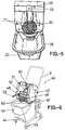
- Figure 5 is a front elevational view of the object shown in Figs. 3 and 4.
- Figure 6 is a perspective view of a third embodiment of the invention.
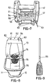
- Figure 7 is a back elevational view of the object shown in Fig. 6.
- Figure 8 is a front elevational and perspective view of a fourth embodiment of the invention.
- Figure 9 is, lastly, a view of the tool acting direct on the surface to be cleaned and then dried, by means of which the squeezing vanes of the mop or scrubber operate.
- From Fig. 1, it can be seen the manner in which the improved automatic mop device for cleaning floors 1 is constituted, starting from a
base 2, preferably made of a stiff material, configured as a platform having wheels at the bottom side thereof 3, the function of these wheels being to make easy the assembly transport. On the platform, there is incorporated acasing 15 housing a motor, mechanisms and feeding battery of the own motor, while on the other side of the casting, aconventional mop bucket 4 is mounted. - The mop device 1 has a
hinged arm 7 with ajoint point 16, ahandle 13 and asliding tube 8 located next the handle orholder 13. - The casing is fastened to the frame or
base 2 by means ofconventional screws 11. - The casing has a
connection intake 10 for receiving the cable of a charger from which the 12V battery is charged. This battery is located within the casing, thru which the motor is fed. - In the same way, this side of the casing has an intake and
connection 12 for a 15 amp fuseholder, and also aswitch 14 for starting the mop. - In the inner center part of the casing, an
arm 5 is installed at the lower middle part of which asqueezing element 9 is located, formed as squeezing vanes. which is inserted into a cavity existing in the upper side of abucket 4, to be used as a squeezing element of the scrubber or mop fringes. - The
arm 5, specifically in its external upper zone, has asupport 6 to which the mop stick is fixed. - The motor drives an assembly of speed demultiplying gears,and, in turn, a power multiplier, so obtaining the adequate speed and power necessary to said arm or
vanes 9 for squeezing the mop fringes. - The motor is fitted with an end-of-stroke acting thru a small notch that opens, and when the end-of-stroke is effected, it reverses the polarity to the motor, thereby the
arm 9 returns to its - rest position. Then, the squeezing operation is started again so many times as required. - In turn, the end-of-stroke switcj limits the course of the motor driving the squeezing arm.
- Figures 3, 4 and 5 show different views of a second embodiment of the invention, referred, in general, as 20, which is constituted starting from a
bucket 22 made of any material, situated on the upper surface of a support andtranslation part 23 fitted withfree turning wheels 24, thebucket 22 having a handle or holder - 26, knurled at its center position to make easy its grasping and adherence to the user's hand. - A squeezing
head 25 is mounted on thebucket 22 by conventional means, which is formed by a casing housing an electric motor, a shaft, gears, a battery and a relay (not shown in the figure, as they are conventional elements, coupled one other in order to achieve the purpose of driving squeezing vanes), the function of the motor being to receive the battery or accumulator current after anexternal switch 29, located within anotch 28 having a semicircular arc shape, vertically situated, is pressed by the handle or holder of the mop with a ligtht pressure, a relay acting once theswitch 29 has been operated, giving the appropiate orders to the inside of the squeezing head with the purpose of causing the motor to act, starting to turn, and setting in motion a shaft acting on the squeezing arms orvanes 27, exerting a pressure on the mop or scrubber located within the basket acting as afilter 30, squeezing the content of water from the mop, this water passing inside thebucket 22, the dirtiness potentially dragged by the mop during the cleaning or washing operation on the surface, resting on the surface of thefilter 30. - Once the turning has been effected, the shaft, acting in cooperation with the gears due to the fact that it is fitted with a notch acting as end-of-stroke, stops the motion of the squeezing arms or
vanes 27, and the presioning operation on the mop by means of the squeezing vanes orarms 27 can be repeated upon acting again on theswitch 29, turning the motor fed by an electric current obtained from the battery or accumulator, and commencing again the cycle. - The
bucket 22 has, on its upper edge, a diametrical trimming stiffing it in order to allow a coupling of the squeezinghead 25. - The squeezing
head 25 has, in its external portion, exactly on one of its sides, alight pilot 34, showing every moment that the battery or accumulator incorporated inside the squeezinghead 25 is being charged by means of an electric current intake configurated as a flexible cable having, at one of its ends, a female pin incorporated in theintake 35, while the other end of the cable has a male pin connected to a conventional electric power intake. - Also, the squeezing
head 25 has apilot 31 to be lighted on when thelighting switch 32 has been actuated, this switch allowing - that, by operating the grasping element or handle which carries the mop, exactly by the pressure exerted by the user and through the stick on theswitch 29, thearms 27 act, squeezing the water carried by the mop and dropping within thebucket 22 thru the bascket orfilter 30. - Lastly, it should be pointed out that the mop device is fitted with a
protection fuse 33. - As a complement to the description made on the second embodiment, it should be noted that once the cleaning operations have been ended, the squeezing
head 25 can be removed from its operational housing, and once thebucket 22 has been duly cleaned up, the squeezinghead 25 can be housed within thebucket 22, occupying a minimal space. - Figures 6 and 7 show a third embodiment of the invention, which has been referenced in a general way with 40, and being constituted starting from a casing or
frame 42, on which all the acting mechanisms of the object of the invention are placed, and this assembly of frame or similar 42 being placed on aconventional bucket 43 by usinganchoring links 59 located on the back - side thereof, and having lateral projections emerging fromsteps 60 formed or located at the lower part of the main part. - The frame or
casing 42 is located on abucket 43, and this, in turn, is placed on atransport carriage 44 fitted withappropiate wheels 45, and it can optionally carry abasket 47 to contain auxiliary elements for cleaning purposes, such as a spare mop, the basket being installed on the vertical arms of handle 46, which facilitates the motion of the assembly composed of a bucket carrying the squeezer on its upper mouth and fixed to one of its - side branches. - As can be seen in Fig. 6, the squeezer has a retaining link for the
mop holder 48, fixed to a front area, presenting a center recesss on theupper portion 50, fitted with a switch thru which and with the assistance of the mop o scrubber stick, a light pressure is exerted on said switch,setting automatically in motion the motors in a sense or other, according to the turning of the current obtained from the battery and being determined by a relay driven by saidswitch 50, and thanks to the cooperation of an end-of-stroke switch (non referenced). - When the operating
switch 50 is enabled, that is to say, when it is subject to the tool and handle or holder of the mop or scrubber pressure, the motor will run in the desired sense, moving the gear assemblies and these latter, in turn, will move thearms arms bucket 43 on which the assemby is installed. - As can be seen in Fig. 7, the invention relais on a lighting -
pilot 54, a main switch 55 and a rapid access protection relay - 56, located on one of the back sides offrame 42, while on the opposite side, acharge indicator pilot 57 is installed, which acts as an indicator for the electric power fed by the battery (not - shown) through aconventional cable 53 plugged in a plug located at the squeezer, and having the other end connected to a conventional socket linked to the electric network. - The side vanes of
support 60, located at the lower part of the frame orcasing 42, can optionally have two emerging stubs 58 to be duly engaged on the side walls ofbucket 43, exactly on the upper inner zone thereof. - In Fig. 8, a fourth embodiment of the invention is illustrated, with
general reference 70, which is constituted, as in previous - cases, starting from abucket 71 made of an appropiate material having a plantar rectangular shape and having all its vertices rounded, presenting, at its upper portion, a perimetral oversized edge acting as a reinforcement link of theown bucket 71, allowing-to fix on same a body 74, inside which all acting elements of the - object of the invention are incorporated. - The
bucket 71 has a handle orholder 75 and it is situated on aplatform 72 provided with free turning wheels 73 to make easy its transportation and avoid the user to carry out efforts during the cleaning operations. - On the perimetral edge of the main body of
bucket 71, a body containing mechanical and electric elements 74 is installed, having abasket 79 presenting a plurality of perforations in order to allow to pass the water taken out from the mop or scrubber, themain body 79 having a reverse truncated cone shape and withinner vanes 76 acting to perform the mop or scrubber squeezing, thesevanes 76 being moved by the motor located in the frame or casing shaping the body 74. - On the upper portion of the main body 74, frame or casing, a
pilot light 80. amain switch 81, afuse holder 82, anindicator 83 are arranged, the function of saidindicator 83 being to inform the user about the necessity of recharge the battery located inside, by engaging a feeder in the base ofsocket 84. - In syntesis, the automatic mop device, by means of the
vanes 76 emerging from the inner walls ofbasket 79, squeezes the fringes - emerging from the mop stick (shown in Fig. 9 with no reference), thevanes 76 exerting an adequate pressure to attain a full squeezing of same. - Owing to an inner circuit which operates when the mop is inserted into the reverse truncated cone shaped
basket 79, and by simply approaching the stick of the mop or scrubber to the front end of frame, the stick, fitted with aninner magnet 85 adequately dimensioned, sets in operation the inner circuit which has a timer which operates for an adequate time the squeezingvanes 76, this operation being enhanced with regard to the inner circuit by a microswitch.
Claims (5)
- An automatic mop device for cleaning floors, comprising a stick or holder being markedly elongated and cylindrical, made of any material, said stick or holder receiving, at one of its ends, a part formed by fringes made of a textile material and capable of absorbing liquids, a bucket (4) or receptacle, of any material or shape, a platform (2) acting as a base having below it free turning wheels (3) which allow the device to be transported, the platform (2) having, on a side, a casing (15) which houses an electric motor, characterized by the electric motor being fitted with an end-of-stroke switch, a 12V battery for feeding electric power to the motor and the relative connections, the casing (15) having, on a side, a first arm composed of two lengths (7-7'), which are hinged at a point (16), the first arm being fitted with a handle or holder (13) and a sliding tube (8), the function of the tube (8) being to fix both lengths (7-7'), a second arm (5) emerging from the center end of the casing (15), having at its lower middle part a complementary squeezing arm (9), incorporated in the squeezing area of the bucket (4) located on the platform (2), the second arm (5) having at one end a switch (6) acting in cooperation with the mop stick; in particular, a bucket (22) stiffened by oversize at its perimeter, on which there is located a squeezing head (25) fixed thereto by conventional means, inside of which there are arranged acting elements, which are set in operation by pressing the mop stick on a switch (29) located on the front end of the casing formed by the squeezing head (25), which has, in the middle portion, a recess (28) in which the switch (29) is located, which acts on a relay and, then, on the rest of the mechanisms until operating the end-of-stroke switch, setting in operation external arms or vanes (27) which are set in motion towards inside a basket (30) on which the mop has previously been located; in particular, a casing or squeezing head (42)being fixed to the upper portion of a conventional bucket (43), having anchoring flanges (19) located at the back and lower part of same, and having lower shoulders (60), in particular being fitted with emerging stubs (58) to be fixed to the inner wall of the carrier bucket (43), the casing or squeezing head (42) having a grating (49) acting as a filter, there being inside the casing or squeezing head (42) two motors and two gear assemblies laterally arranged, both motors being driven by two batteries, having a pilot light (57) to indicate the recharge operation of the batteries when required, the pluriperforated basket acting as a filter and being configured as a basket (79), in particular being fitted with two vanes (76) emerging from the inner wall, and the mop stick having a magnet (85), which, when approaching the front end of the casing, enables a microswitch moving the vanes (76) for a predetermined period of time, controlled by a timer located within the casing or squeezing head (42).
- An automatic mop device according to claim 1, characterized in that on the external surface of the casing (15), a base (10) has been arranged for incorporating a battery charger, a main switch (14), and a fuseholder of 15 amperes (12), the casing (15) being fixed to the platform (2) by means of screws (11).
- An automatic mop device according to claims 1 and 2, characterized in that the motor has its motion limited in a predetermined time for performing the squeezing of the fringes, while the rest time is determined by an end-of-stroke switch reversing the motor polarity and changing its turning sense, the end-of-stroke switch being configured by a notch that, when open, reverses the motor polarity,the arm returning to its rest position,allowing to reset the squeezing operation by pressing the switch (6).
- An automatic mop device according to claim 1, characterized in that on one of the external surfaces of the squeezing head there is located a pilot (34) indicating that the battery or accumulator are being recharged through a flexible electric cable connected to the mains, relying on a main switch (32), setting in operation a pilot light (31) to inindicate the starting of the automatic mop device, and having a protection fuse (33).
- An automatic mop device according to claim 1, characterized in that when having two motors, these will turn in one sense or another, depending on the sense in which they receive the battery current, this actuation being determined by a relay operated by a switch (59) and having an end-of-stroke switch, the switch (59) being enabled by the mop holder or handle.
Applications Claiming Priority (8)
| Application Number | Priority Date | Filing Date | Title |
|---|---|---|---|
| ES9300636U ES1024001Y (en) | 1993-03-11 | 1993-03-11 | AUTOMATIC MOP PERFECTED FOR FLOOR CLEANING. |
| ES9300636U | 1993-03-11 | ||
| ES9302508U | 1993-09-21 | ||
| ES9302508U ES1025724Y (en) | 1993-09-21 | 1993-09-21 | AUTONOMOUS AND AUTONOMIC DRAINER OF MOPES AND MOPES. |
| ES9302507U | 1993-09-21 | ||
| ES9302507U ES1025723Y (en) | 1993-09-21 | 1993-09-21 | PERFECTED AUTOMATIC MOP. |
| ES9303452U ES1026770Y (en) | 1993-12-27 | 1993-12-27 | PERFECTED AUTOMATIC MOP. |
| ES9303452U | 1993-12-27 |
Publications (2)
| Publication Number | Publication Date |
|---|---|
| EP0614644A1 EP0614644A1 (en) | 1994-09-14 |
| EP0614644B1 true EP0614644B1 (en) | 1997-09-10 |
Family
ID=27443910
Family Applications (1)
| Application Number | Title | Priority Date | Filing Date |
|---|---|---|---|
| EP94500047A Expired - Lifetime EP0614644B1 (en) | 1993-03-11 | 1994-03-10 | Automatic mop device |
Country Status (3)
| Country | Link |
|---|---|
| EP (1) | EP0614644B1 (en) |
| AT (1) | ATE157849T1 (en) |
| DE (1) | DE69405428T2 (en) |
Families Citing this family (6)
| Publication number | Priority date | Publication date | Assignee | Title |
|---|---|---|---|---|
| EP0797948B1 (en) * | 1996-03-27 | 2000-08-23 | Jens Diehl | Device for cleaning an implement with a sponge |
| US6065175A (en) * | 1998-08-13 | 2000-05-23 | Tejerina; Silvia Reyero | Flooring mopping system |
| ES2246620B2 (en) * | 2003-01-16 | 2006-12-16 | Sprimsol Limpiezas, S.L. | AUTOMATIC ESCURRIDOR TO ROLLERS OF MOPAS AND SIMILAR. |
| CN108814485B (en) * | 2018-08-06 | 2023-11-10 | 浙江美添乐家居用品股份有限公司 | Dehydration and cleaning integrated mop bucket |
| CN112294211B (en) * | 2020-10-29 | 2021-09-07 | 台州市黄岩金多塑业有限公司 | Mop washing barrel capable of automatically removing sundries on mop |
| NL1044299B1 (en) | 2022-04-12 | 2023-11-03 | Reborg Solutions B V | Device and method for squeezing a wet cloth |
Family Cites Families (7)
| Publication number | Priority date | Publication date | Assignee | Title |
|---|---|---|---|---|
| DE2227554A1 (en) * | 1972-06-07 | 1973-12-20 | Gustav Huebner | CLEANING MACHINE FOR CLOTHS AND PUGS, IN PARTICULAR SCOPPING AND DRYING CLOTHS, AS WELL AS SCRUBBING AND DRYING MOPS AND CLEANING CLOTHS |
| US3987513A (en) * | 1975-12-18 | 1976-10-26 | Gonzales Charles M | Mop wringer |
| US4344201A (en) * | 1980-12-03 | 1982-08-17 | Trisolini George S | Cleaning apparatus |
| US4722113A (en) * | 1985-12-02 | 1988-02-02 | Olsson Arvid T | Mop handle stabilizer |
| DE4023219A1 (en) * | 1990-07-21 | 1992-01-23 | Dieter Sacks | PRESSING DEVICE FOR CLEANING CLOTHS AND THE LIKE |
| FR2672791B1 (en) * | 1991-02-14 | 1994-12-23 | Maxnet | SPIN-OUT DEVICE FOR BROOM HEAD. |
| JPH0724645B2 (en) * | 1991-05-31 | 1995-03-22 | 修三 小野寺 | Automatic water absorption device for mop cleaning |
-
1994
- 1994-03-10 EP EP94500047A patent/EP0614644B1/en not_active Expired - Lifetime
- 1994-03-10 AT AT94500047T patent/ATE157849T1/en not_active IP Right Cessation
- 1994-03-10 DE DE69405428T patent/DE69405428T2/en not_active Expired - Lifetime
Also Published As
| Publication number | Publication date |
|---|---|
| ATE157849T1 (en) | 1997-09-15 |
| DE69405428D1 (en) | 1997-10-16 |
| DE69405428T2 (en) | 1998-04-16 |
| EP0614644A1 (en) | 1994-09-14 |
Similar Documents
| Publication | Publication Date | Title |
|---|---|---|
| US4875246A (en) | Surface treating device | |
| EP3838096B1 (en) | Surface cleaning apparatus | |
| US7434292B2 (en) | Automatic roller wringer | |
| US7174603B2 (en) | Multi-purpose position sensitive floor cleaning device | |
| US7861351B2 (en) | Electric cleaning sweeper | |
| CN101384205B (en) | Power mop with exposable scrub brush | |
| EP2568863B1 (en) | Method of cleaning mop material | |
| EP0614644B1 (en) | Automatic mop device | |
| WO1998029020A3 (en) | Cordless wet mop and vacuum assembly | |
| CN211511662U (en) | Floor wiping machine charging dock | |
| CN203000816U (en) | Electric sweeper | |
| MX2007014947A (en) | Fabric sweeper. | |
| CN216495125U (en) | Cleaning device | |
| WO2015189563A1 (en) | Apparatus for cleaning a floor surface | |
| US4959628A (en) | Rotating electric switch actuated by fixed magnetic means, usable for a surface cleaning device | |
| KR102110385B1 (en) | Multi purpose wet duster using natural pulp | |
| CN213321876U (en) | Dry-wet separation equipment for kitchen garbage | |
| KR200458082Y1 (en) | a wet floorcloth cleaner of floorcloth fiber mounting and holder having thereof | |
| WO2019026882A1 (en) | Electric vacuum cleaner | |
| CN215099074U (en) | Automatic empty tray collecting and distributing unit | |
| JPS6314762Y2 (en) | ||
| IT9021965U1 (en) | MANUAL OR ELECTRIC SWEEPING COLLECTION DEVICE APP LICABLE TO ANY PURPOSE | |
| JPH08140920A (en) | Electric hand-held cleaner | |
| KR20070117828A (en) | An automatic roller wringer for mops and the like | |
| JP3106567U (en) | Plastic compressor |
Legal Events
| Date | Code | Title | Description |
|---|---|---|---|
| PUAI | Public reference made under article 153(3) epc to a published international application that has entered the european phase |
Free format text: ORIGINAL CODE: 0009012 |
|
| AK | Designated contracting states |
Kind code of ref document: A1 Designated state(s): AT BE CH DE FR GB GR IE IT LI NL PT SE |
|
| 17P | Request for examination filed |
Effective date: 19950206 |
|
| 17Q | First examination report despatched |
Effective date: 19960326 |
|
| GRAG | Despatch of communication of intention to grant |
Free format text: ORIGINAL CODE: EPIDOS AGRA |
|
| GRAH | Despatch of communication of intention to grant a patent |
Free format text: ORIGINAL CODE: EPIDOS IGRA |
|
| GRAH | Despatch of communication of intention to grant a patent |
Free format text: ORIGINAL CODE: EPIDOS IGRA |
|
| GRAA | (expected) grant |
Free format text: ORIGINAL CODE: 0009210 |
|
| AK | Designated contracting states |
Kind code of ref document: B1 Designated state(s): AT BE CH DE FR GB GR IE IT LI NL PT SE |
|
| PG25 | Lapsed in a contracting state [announced via postgrant information from national office to epo] |
Ref country code: LI Effective date: 19970910 Ref country code: GR Free format text: LAPSE BECAUSE OF FAILURE TO SUBMIT A TRANSLATION OF THE DESCRIPTION OR TO PAY THE FEE WITHIN THE PRESCRIBED TIME-LIMIT Effective date: 19970910 Ref country code: CH Effective date: 19970910 Ref country code: AT Effective date: 19970910 |
|
| REF | Corresponds to: |
Ref document number: 157849 Country of ref document: AT Date of ref document: 19970915 Kind code of ref document: T |
|
| REG | Reference to a national code |
Ref country code: CH Ref legal event code: EP |
|
| REF | Corresponds to: |
Ref document number: 69405428 Country of ref document: DE Date of ref document: 19971016 |
|
| ITF | It: translation for a ep patent filed |
Owner name: STUDIO TORTA S.R.L. |
|
| ET | Fr: translation filed | ||
| REG | Reference to a national code |
Ref country code: IE Ref legal event code: FG4D Free format text: 76371 |
|
| REG | Reference to a national code |
Ref country code: PT Ref legal event code: SC4A Free format text: AVAILABILITY OF NATIONAL TRANSLATION Effective date: 19971203 |
|
| REG | Reference to a national code |
Ref country code: CH Ref legal event code: PL |
|
| PLBE | No opposition filed within time limit |
Free format text: ORIGINAL CODE: 0009261 |
|
| STAA | Information on the status of an ep patent application or granted ep patent |
Free format text: STATUS: NO OPPOSITION FILED WITHIN TIME LIMIT |
|
| 26N | No opposition filed | ||
| REG | Reference to a national code |
Ref country code: GB Ref legal event code: IF02 |
|
| PGFP | Annual fee paid to national office [announced via postgrant information from national office to epo] |
Ref country code: IE Payment date: 20100330 Year of fee payment: 17 |
|
| PGFP | Annual fee paid to national office [announced via postgrant information from national office to epo] |
Ref country code: FR Payment date: 20100303 Year of fee payment: 17 |
|
| PGFP | Annual fee paid to national office [announced via postgrant information from national office to epo] |
Ref country code: GB Payment date: 20100323 Year of fee payment: 17 Ref country code: BE Payment date: 20100216 Year of fee payment: 17 |
|
| PGFP | Annual fee paid to national office [announced via postgrant information from national office to epo] |
Ref country code: NL Payment date: 20100223 Year of fee payment: 17 Ref country code: DE Payment date: 20100219 Year of fee payment: 17 |
|
| PGFP | Annual fee paid to national office [announced via postgrant information from national office to epo] |
Ref country code: SE Payment date: 20100305 Year of fee payment: 17 |
|
| BERE | Be: lapsed |
Owner name: *RAMIREZ MORENO MARIA DEL CARMEN Effective date: 20110331 |
|
| REG | Reference to a national code |
Ref country code: NL Ref legal event code: V1 Effective date: 20111001 |
|
| REG | Reference to a national code |
Ref country code: SE Ref legal event code: EUG |
|
| GBPC | Gb: european patent ceased through non-payment of renewal fee |
Effective date: 20110310 |
|
| REG | Reference to a national code |
Ref country code: FR Ref legal event code: ST Effective date: 20111130 |
|
| PG25 | Lapsed in a contracting state [announced via postgrant information from national office to epo] |
Ref country code: BE Free format text: LAPSE BECAUSE OF NON-PAYMENT OF DUE FEES Effective date: 20110331 |
|
| REG | Reference to a national code |
Ref country code: IE Ref legal event code: MM4A |
|
| PG25 | Lapsed in a contracting state [announced via postgrant information from national office to epo] |
Ref country code: NL Free format text: LAPSE BECAUSE OF NON-PAYMENT OF DUE FEES Effective date: 20111001 Ref country code: IE Free format text: LAPSE BECAUSE OF NON-PAYMENT OF DUE FEES Effective date: 20110310 Ref country code: FR Free format text: LAPSE BECAUSE OF NON-PAYMENT OF DUE FEES Effective date: 20110331 Ref country code: DE Free format text: LAPSE BECAUSE OF NON-PAYMENT OF DUE FEES Effective date: 20111001 |
|
| REG | Reference to a national code |
Ref country code: DE Ref legal event code: R119 Ref document number: 69405428 Country of ref document: DE Effective date: 20111001 |
|
| PG25 | Lapsed in a contracting state [announced via postgrant information from national office to epo] |
Ref country code: GB Free format text: LAPSE BECAUSE OF NON-PAYMENT OF DUE FEES Effective date: 20110310 |
|
| PGFP | Annual fee paid to national office [announced via postgrant information from national office to epo] |
Ref country code: IT Payment date: 20120321 Year of fee payment: 19 |
|
| PG25 | Lapsed in a contracting state [announced via postgrant information from national office to epo] |
Ref country code: SE Free format text: LAPSE BECAUSE OF NON-PAYMENT OF DUE FEES Effective date: 20110311 |
|
| PGFP | Annual fee paid to national office [announced via postgrant information from national office to epo] |
Ref country code: PT Payment date: 20130225 Year of fee payment: 20 |
|
| REG | Reference to a national code |
Ref country code: PT Ref legal event code: MM4A Free format text: MAXIMUM VALIDITY LIMIT REACHED Effective date: 20140310 |
|
| PG25 | Lapsed in a contracting state [announced via postgrant information from national office to epo] |
Ref country code: PT Free format text: LAPSE BECAUSE OF EXPIRATION OF PROTECTION Effective date: 20140318 |