EP0613299B1 - Doppelbusarchitektur für Bewegungskompensation - Google Patents
Doppelbusarchitektur für Bewegungskompensation Download PDFInfo
- Publication number
- EP0613299B1 EP0613299B1 EP93115027A EP93115027A EP0613299B1 EP 0613299 B1 EP0613299 B1 EP 0613299B1 EP 93115027 A EP93115027 A EP 93115027A EP 93115027 A EP93115027 A EP 93115027A EP 0613299 B1 EP0613299 B1 EP 0613299B1
- Authority
- EP
- European Patent Office
- Prior art keywords
- memory
- current block
- search window
- pixels
- block
- Prior art date
- Legal status (The legal status is an assumption and is not a legal conclusion. Google has not performed a legal analysis and makes no representation as to the accuracy of the status listed.)
- Expired - Lifetime
Links
Images


Classifications
-
- H—ELECTRICITY
- H04—ELECTRIC COMMUNICATION TECHNIQUE
- H04N—PICTORIAL COMMUNICATION, e.g. TELEVISION
- H04N19/00—Methods or arrangements for coding, decoding, compressing or decompressing digital video signals
- H04N19/42—Methods or arrangements for coding, decoding, compressing or decompressing digital video signals characterised by implementation details or hardware specially adapted for video compression or decompression, e.g. dedicated software implementation
- H04N19/43—Hardware specially adapted for motion estimation or compensation
- H04N19/433—Hardware specially adapted for motion estimation or compensation characterised by techniques for memory access
-
- G—PHYSICS
- G06—COMPUTING OR CALCULATING; COUNTING
- G06T—IMAGE DATA PROCESSING OR GENERATION, IN GENERAL
- G06T7/00—Image analysis
- G06T7/20—Analysis of motion
- G06T7/223—Analysis of motion using block-matching
- G06T7/231—Analysis of motion using block-matching using full search
-
- H—ELECTRICITY
- H04—ELECTRIC COMMUNICATION TECHNIQUE
- H04N—PICTORIAL COMMUNICATION, e.g. TELEVISION
- H04N19/00—Methods or arrangements for coding, decoding, compressing or decompressing digital video signals
- H04N19/10—Methods or arrangements for coding, decoding, compressing or decompressing digital video signals using adaptive coding
- H04N19/102—Methods or arrangements for coding, decoding, compressing or decompressing digital video signals using adaptive coding characterised by the element, parameter or selection affected or controlled by the adaptive coding
- H04N19/103—Selection of coding mode or of prediction mode
- H04N19/107—Selection of coding mode or of prediction mode between spatial and temporal predictive coding, e.g. picture refresh
-
- H—ELECTRICITY
- H04—ELECTRIC COMMUNICATION TECHNIQUE
- H04N—PICTORIAL COMMUNICATION, e.g. TELEVISION
- H04N19/00—Methods or arrangements for coding, decoding, compressing or decompressing digital video signals
- H04N19/50—Methods or arrangements for coding, decoding, compressing or decompressing digital video signals using predictive coding
- H04N19/503—Methods or arrangements for coding, decoding, compressing or decompressing digital video signals using predictive coding involving temporal prediction
- H04N19/51—Motion estimation or motion compensation
-
- H—ELECTRICITY
- H04—ELECTRIC COMMUNICATION TECHNIQUE
- H04N—PICTORIAL COMMUNICATION, e.g. TELEVISION
- H04N19/00—Methods or arrangements for coding, decoding, compressing or decompressing digital video signals
- H04N19/60—Methods or arrangements for coding, decoding, compressing or decompressing digital video signals using transform coding
- H04N19/61—Methods or arrangements for coding, decoding, compressing or decompressing digital video signals using transform coding in combination with predictive coding
Definitions
- the present invention relates to a coder for coding a video image. More particularly, the present invention is related to an architecture which utilizes two sets of memories and two buses to increase the efficiency of use of a Motion Estimation Unit contained within the coder and to smooth the data flow in a pipelined operation of the coder.
- FIG. 1 A video coder is illustrated in FIG 1.
- the video coder 10 operates in accordance with CCITT recommendation H.261 (See “Draft Revision of Recommendation H.261 Video Codec for Audio Visual Services at px64 Kbits/sec", Signal Processing: Image Communication 2 (1990) 221-239, Elsevier).
- the video coder contains an input frame memory 12 for storing a current frame of video to be coded.
- the current frame of video is coded on a block-by-block basis.
- Some frames are coded in accordance with an intra-mode. In the intra-coding mode, no information from a previous frame is utilized and the coding relies entirely on information contained within the current frame.
- Each block of pixels is transmitted from the memory 12, via the multiplexer 14, to the Discrete Cosine Transform (DCT) circuit 16. In the DCT circuit 16, the Discrete Cosine Transform is applied to the block of pixels. The transformed pixels are then thresholded and quantized in the quantizer circuit 18.
- DCT Discrete Cosine Transform
- the quantized, transformed pixels are then coded using the variable length coder (VLC) 20.
- the variable length coded pixels are then transmitted via the multiplexer 22 to the buffer 24.
- the coded pixels are then transmitted from the buffer 24 via a channel 26 to a particular destination, where the pixels are decoded.
- the quantization controller 27 may vary the threshold and quantization stepsize utilized by the quantizer circuit 18. Information as to the threshold and quantization stepsize used to code a particular block is transmitted to the destination via line 23, the multiplexer 22, the buffer 24, and the channel 26.
- the output of the quantizer circuit 18 is connected to the inverse quantizer circuit 28 and Inverse Discrete Cosine Transform (IDCT) circuit 29. These two circuits serve to reconstruct a block of pixels coded according to the intra-mode.
- the reconstructed block of pixels is stored in a previous frame memory system 30.
- the multiplexer 32 outputs zero so the adder 34 adds nothing to the output of the IDCT circuit 29.
- the output of the IDCT circuit 29 is connected directly to the previous frame memory system 30, without change.
- Some frames are coded using a technique known as predictive mode coding.
- predictive mode coding When a frame is coded using the predictive mode, some blocks are coded using the intra-mode described above and some blocks are coded using an inter-mode described below.
- the inter-mode requires information from both the previous frame and the current frame. For a frame coded using the predictive mode, a decision as to whether to use the inter or intra-mode is made on a block-by-block basis.
- the first step in deciding whether to use the intra-mode or the inter-mode for a current block is to first find the best match of the current block in the previous frame.
- the processor circuit 300 contains a Motion Estimation Unit (MEU) 31, a Motion Compensation (MC) Decision Unit 32, and an Inter/Intra Decision Unit 33.
- the current block of the current frame is transmitted from the input frame memory 12 to the MEU 31.
- a search window of the previous frame, which previous frame is stored in the previous frame memory system 30, is also transmitted to the MEU circuit 31.
- the search window of the previous frame includes the pixels of the previous frame which correspond to the pixels of the current block of the current frame as well as additional pixels in each dimension to define a search window.
- the search window comprises the pixels in the previous frame which correspond to the 16x16 current block as well as ⁇ 7 pixels in each dimension.
- the error between the 16x16 current block and each possible 16x16 block in the search window is then determined.
- the block in the search window which results in the minimum error is then determined.
- the MC decision unit 32 determines whether or not to use motion compensation for each current block in the current frame.
- the algorithm used to make the decision may be understood with help of FIG 2.
- the vertical axis represents possible values of the error between the current block and the block in the search window which results in the minimum error.
- the actual errors between the current block and the best match and zero displacement blocks of the search window define a point in the graph of FIG 2. If this point is in the shaded region of FIG 2 (excluding the decision curve) motion is detected and motion compensation is used for the current block. If the point is outside the shaded region, motion compensation is not used for the current block.
- the Inter/Intra Decision Unit 33 decides whether to use intra-mode or inter-mode coding for the current block. If motion compensation is to be used, then the best match (i.e., minimum error) block of the search window is used for the inter/intra decision. If motion compensation is not used for the current block, then the inter/intra decision is made using the zero displacement block of the search window.
- the inter/intra decision is as follows: the variance of the current block and the variance of the error between the current block and the best match or zero displacement block (depending on whether or not there is Motion Compensation) are determined.
- inter or intra mode coding is utilized in accordance with FIG 3.
- the decision as to whether to use inter or intra coding is transmitted from the MC circuit to the multiplexer 12 via line 35.
- the current block is transmitted from the frame memory 12, via the multiplexer 14, to the DCT circuit 16 and the block is coded directly using the DCT circuit 16, the quantizer 18, and the VLC circuit 20 in the manner discussed above.
- the inverse quantizer 28 and IDCT circuit 29 are used to reconstruct the block for storage in the previous frame memory 30.
- the best match or zero displacement block (depending on whether or not Motion Compensation is used) from the previous frame is retrieved from the previous frame memory system 30 and is filtered by the loop filter 38, which filter performs a smoothing function.
- the subtractor 39 is then used to obtain the difference between the current block and best match or zero displacement block from the previous frame.
- the difference is then transmitted from the subtractor 39, via the multiplexer 14, to the DCT circuit 16.
- the difference is transformed using the DCT circuit 16.
- the resulting transform coefficients are then thresholded and quantized using the quantizer circuit 18.
- the resulting coefficients are coded using the VLC 20 and transmitted via the multiplexer 22, the buffer 24, and the channel 26 to a destination.
- the difference is reconstructed using the inverse quantizer 28 and IDCT circuit 29.
- the output of the filter 38 is transmitted via the multiplexer 33 to the adder 34.
- the adder 34 combines the reconstructed difference at the output of the IDCT circuit 29 with the output of the filter 38 to reconstruct the current block.
- the current block is then stored in the previous frame memory system 30.
- one frame is entirely intra-mode coded and the alternate frame is coded using a predictive mode in the manner described above.
- motion compensation in the video coder has a number of significant advantages. Based on persistence of vision, a television signal has to be scanned at a speed of 30 frames/sec. However, in many applications, such as video conferencing there is a large amount of redundancy between frames. The use of motion compensation in the manner described above, reduces this redundancy and allows the video signal to be highly compressed.
- a variety of different algorithms can be used to estimate the motion between a block of pixels of the current frame and the previous frame which is stored in the previous frame memory 30 of FIG 1. For example, a pixel recursive algorithm is disclosed in A.N. Netravali et al., "Motion Compensation Television Coding: Part I", BSTT, Vol. 58, pp.
- the present invention is a memory architecture for use in a video coder.
- the memory architecture contains first and second memories. Each memory has capacity to store a current block from a current frame and a corresponding search window from a previous frame.
- the memory architecture of the present invention is utilized when the video coder is operating in the predictive mode.
- the memory architecture operates in cycles.
- the i th cycle the i th block from the current frame and the corresponding search window from the previous frame are stored in the first memory.
- the i th cycle the i th block of the current frame and the corresponding search window are repeatedly accessed and processed by the motion estimation unit.
- the (i-1) th block of the current frame and the corresponding search window from the previous frame are stored in the second memory. (These were written into the second memory during the (i-1) th cycle).
- the (i-1) th current block and the best match or zero displacement block of the corresponding search window are outputted to the inter/intra decision unit and/or the DCT loop in the video coder.
- the (i+1) th current block and the corresponding search window of the previous frame are written into the second memory.
- the motion estimation unit repeatedly accesses and processes the (i+1) th current block of the current frame and corresponding search window of the previous frame which are now stored in the second memory.
- the i th current block and zero displacement or best match block from the corresponding search window are outputted from the first memory to the inter/intra decision circuit and/or DCT loop of the video coder.
- the (i+2) th current block and corresponding search window are written into the first memory.
- dual buses are utilized to move pixel data into and out of the first and second memories, i.e., a first bus transports current block pixel data into and out of the first and second memories and a second bus transports search window pixel data into and out of the first and second memories.
- FIG 1 schematically illustrates a video coder circuit.
- FIG 2 is a graph for use in deciding whether or not to use motion compensation for a block of pixels.
- FIG 3 is a graph for use in deciding whether to use inter or intra mode coding for a block of pixels.
- FIG 4 shows how the memory architecture of the present invention interconnects with the video coder circuit of FIG 1.
- FIG 5 is a timing diagram for the memory architecture of the present invention.
- FIG 6 is a detailed circuit implementation of the memory architecture of the present invention.
- FIG 4 also shows the interconnection between the memory architecture 100 and the video coder 10 of FIG 1. As indicated above, the memory architecture is utilized when the video coder 10 codes in the predictive mode.
- the memory architecture 100 comprises two memories, labeled Memory A and Memory B.
- Memory A and Memory B each have sufficient capacity to store one block of pixels from the current frame and a corresponding search window from the previous frame.
- a block of pixels from the current frame is transmitted to the memory architecture 100 from the input frame memory 12 via connection path 101.
- the corresponding search window of the previous frame is transmitted to the memory architecture 100 from the previous frame memory system 30 via a connection path 103.
- the memory architecture 100 includes an output 120 for transmitting pixels a(i,j) of a current block to the Motion Estimation Unit 31 of FIG 1 and also one or more outputs 122 for transmitting pixels b(i-m,j-n) of a corresponding search window of the previous frame to the MEU 31 (For example, the MEU of U.S. Patent 4,897,720 receives the pixels of the search window via two inputs).
- the memory architecture 100 receives back from the MEU 31, via the input 123, a best match displacement vector m*,n* and/or an MC decision indicator signal which indicates whether or not Motion Compensation will be utilized in the coding of the current block.
- the memory architecture 100 reads out via the output 124, a current block and either the best match or zero displacement block from the search window (depending on whether or not motion compensation is used). These pixel blocks are buffered in the SRAMs 127 before being transmitted to the intra/inter decision unit 33 (see FIG 1) and/or the DCT coding loop of the video coder.
- the previous frame memory system 30 is also shown in greater detail in FIG 4.
- the previous frame memory system 30 comprises two frame memories labeled Previous Frame Memory A and Previous Frame Memory B.
- the previous frame memory system 30 also comprises a first bus 105 and a second bus 107 and two switches S1 and S2.
- the Previous Frame Memory A and the Previous Frame Memory B operate as follows. In a first position of the switches S1 and S2, reconstructed blocks of the current frame are transmitted from IDCT circuit 29, via input 109, switch S2, and bus 105 into Previous Frame Memory A. Search window pixels of the previous frame are transmitted from Previous Frame Memory B via bus 107, switch S1, output 111, and connection path 103 to the memory architecture 100. After the current frame, in reconstructed form, is completely stored in Previous Frame memory A, the switches S1 and S2 change position, so that for the next frame, search windows are read out of Previous Frame Memory A and reconstructed pixel blocks are written into Previous Frame Memory B.
- the operation of the memory architecture 100 may be understood in greater detail with the help of the timing diagram of FIG 5.
- the operation of the memory architecture 100 takes place in cycles.
- An example of the operation is as follows.
- the (i-1) th current block of the current frame and the corresponding search window of the previous frame are stored in the Memory A and the (i-2) th current block and corresponding search window are stored in the Memory B. Pixels of the (i-1) th current block and the corresponding search window are accessed on an "as needed basis" from the Memory A via the outputs 120, 122. This enables the MEU to perform the motion estimation function.
- the (i-2) th current block of the current frame and a best match or zero displacement block from the corresponding search window are read out of the Memory B via the output 124.
- the i th block of the current frame and the corresponding search window from the previous frame are transferred from the input frame memory 12 and previous frame memory system 30, respectively, into the Memory B.
- pixels of the i th block of the current frame and the corresponding search window of the previous frame are accessed as needed from the Memory B by the MEU via the outputs 120, 122.
- the MEU performs its motion estimation and detection operation and the motion vector m*,n* and MC decision are returned from the MEU to the memory architecture 100 via the input 123.
- the (i-1) th current block and the best match or zero displacement block from the search window are read out from the Memory A, and transmitted via the output 124 to the appropriate SRAM 127.
- the (i+1) th block from the current frame is transmitted from the input frame buffer 12 into the Memory A and the corresponding search window is transmitted from the previous frame memory system 30 into the Memory A.
- Operation then continues into the (i+1) th cycle, wherein block matching takes place in the MEU for the (i+1) th block now stored in the Memory A, the i th block is transmitted out of Memory B along with the best match or zero displacement block from the search window, and the(i+2) th current block and corresponding search window are written into the Memory B.
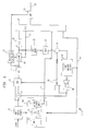
- the memory architecture 100 comprises a Memory A and a Memory B.
- the Memory A comprises a current Block Memory A for a current block and a Search Window Memory A for a corresponding search window.
- the Memory B comprises a current block Memory B for a current block and a Search Window Memory B for a corresponding search window.
- the memory architecture 100 also comprises two buses B1 and B2. Associated with the bus B1 are three switches S3, S4 and S4 .
- the switch S3 has a left state (input connected to left output) and a right state (input connected to right output).
- the switch S4 has a left state (left input connected to the output) and a right state (right input connected to the output).
- the switch S4 also has a left state and a right state.
- pixel data is transferred from the input frame memory to Current Block Memory A or B.
- pixel data is transferred from the current Block Memory A or B to the MEU via output 120.
- pixel data is transferred from Current Block Memory A or Current Block Memory B via the output 124 to the Inter/Intra Decision Unit and/or DCT filter loop.
- the switch Sf is associated with the bus B2.
- the switch Sf has an upstate (input connected to upper output) and a down state (input connected to the lower output).
- search window pixel data from the previous frame memory system 30 is transmitted into Search Window Memory A or Search Window Memory B.
- switches Sp and Sp' Associated with the bus B2 are the switches Sp and Sp'. These switches can have an upstate (upper input connected to the output) or a downstate (lower input connected to the output). Depending on the state of Sp and Sp', pixel data is transferred from Search Window Memory A or B via outputs 122 to the MEU.
- the switch Sl is also associated with the bus B2.
- the switch Sl has an upstate (upper input connected to the output) and a downstate (lower input connected to the output).
- pixel data from Search Window Memory A or B is transmitted via output 124 to the Inter/Intra Decision Unit and/or the DCT loop.
- the memory architecture 100 operates cyclically.
- the switches described above operate as follows in one cycle of the cyclical operation.
- the process is the same except that the switches are reversed because pixel data from Memory B is transferred to the MEU and pixel data from Memory A is transferred to the outputs 124 and the next current block and corresponding search window is then written into Memory A.
- the memory 100 architecture may include an additional switch Sm associated with the bus B2.
Landscapes
- Engineering & Computer Science (AREA)
- Multimedia (AREA)
- Signal Processing (AREA)
- Computer Vision & Pattern Recognition (AREA)
- Physics & Mathematics (AREA)
- General Physics & Mathematics (AREA)
- Theoretical Computer Science (AREA)
- Compression Or Coding Systems Of Tv Signals (AREA)
Claims (7)
- Videokodierer (10), umfassend einen Eingangsbildspeicher (12), der ein momentanes, zu kodierendes Videobild speichert, eine Kodierungsschaltung zum Kodieren des momentanen Bildes, das in dem momentanen Bildspeicher gespeichert ist, unter Verwendung einer Bewegungsauswertung, einen Vorherbild-Speicher (30 A/B) zum Speichern eines vorhergehenden Bildes, das von der Kodierungsschaltung kodiert ist, und eine Speicherarchitektur (100), umfassenddadurch gekennzeichnet, daß ein erster Bus (B1) zum selektiven Anschließen des ersten momentanen Blockspeichers und des zweiten momentanen Blockspeichers an den Eingangsbildspeicher (12) des Videokodierers vorgesehen ist, sowie eine Bewegungsauswertungseinheit (31) des Videokodierers und eine Inter/Intramodus-Entscheidungseinheit (33) des Videokodierers, wobei der erste Bus (B1) der Kodierungsschaltung in einem i-ten Zyklus einer Zyklussequenz den Zugriff auf einen i-ten momentanen Pixelblock von einem der ersten und zweiten momentanen Blockspeicher zur Bewegungsauswertung und -kompensation ermöglicht, um einen (i-1)-ten momentanen Pixelblock von dem anderen der momentanen Blockspeicher zu der Kodierungsschaltung zum Kodieren zu übertragen, und um einen (i+1)-ten momentanen Pixelblock von dem Eingangsbildspeicher (12) zu dem anderen der momentanen Blockspeicher zu übertragen.einen ersten Speicher (Speicher A) mit einem ersten momentanen Blockspeicher und einem ersten Suchfensterspeicher zum selektiven Speichern eines momentanen Pixelblocks eines momentanen, zu kodierenden Videobildes, bzw. eines entsprechenden Suchfensters von Pixeln eines vorhergehenden Videobildes,einen zweiten Speicher (Speicher B) mit einem zweiten momentanen Blockspeicher und einem zweiten Suchfensterspeicher zum selektiven Speichern eines momentanen Pixelblocks eines momentanen, zu kodierenden Videobildes, bzw. eines entsprechenden Suchfensters von Pixeln eines vorhergehenden Videobildes,
und daß ein zweiter Bus (B2) zum selektiven Anschließen des ersten Suchfensterspeichers und des zweiten Suchfensterspeichers an einen Vorherbild-Speicher (30 A/B) des Videokodierers (10) und die Entscheidungsschaltung des Videokodierers vorgesehen ist, wobei der zweite Bus (B2) der Kodierungsschaltung in dem i-ten Zyklus den Zugriff auf Suchfensterpixel von dem einen der Suchfensterspeicher, die dem einen momentanen Blockspeicher entsprechen, zur Bewegungsauswertung und -kompensation des i-ten momentanen Blocks ermöglicht, um einen am besten übereinstimmenden oder Nullverschiebungsblock von Pixeln von dem anderen der Suchfensterspeicher zu der Kodierungsschaltung zum Kodieren des (i-1)-ten momentanen Blocks zu übertragen, und um ein Suchfenster von Pixeln, das dem (i+1)-ten momentanen Block entspricht, von dem Vorherbild-Speicher (30 A/B) zu dem anderen der Suchfensterspeicher zu übertragen. - Videokodierer (10) nach Anspruch 1, wobei die Kodierungsschaltung eine Inter/Intramodus-Entscheidungsschaltung (33), eine diskrete Kosinustransformationsschaltung (16), eine Quantisierschaltung (18) und einen Variablen-Längen-Kodierer (20) zum Kodieren des (i-1)-ten momentanen Blocks umfaßt.
- Videokodierer (10) nach Anspruch 2, wobei die Kodierungsschaltung eine Bewegungsauswertungseinheit (31) und eine Bewegungskompensations-Entscheidungseinheit (32) zum Auswerten und Kompensieren der Bewegung in dem i-ten momentanen Block umfaßt.
- Verfahren zum Betreiben eines Videokodierers nach einem der Ansprüche 1 bis 3, umfassend die Schritte:in einem i-ten Zyklus einer Zyklussequenz, die Ausführung einer Bewegungsauswertung für einen i-ten momentanen Pixelblock eines momentanen Videobildes durch Zugriff zur Verwendung durch eine Bewegungsauswertungseinheit der Videokodierschaltung auf den i-ten momentanen Pixelblock, der in einem der ersten und zweiten momentanen Blockspeicher gespeichert ist, und auf ein Suchfenster von Pixeln, das in dem entsprechenden der Suchfensterspeicher gespeichert ist,in einem ersten Teil des i-ten Zyklus, die Übertragung eines (i-1)-ten momentanen Pixelblocks von dem anderen der momentanen Blockspeicher zu der Videokodierschaltung und die Übertragung von dem anderen der Suchfensterspeicher von am besten übereinstimmenden oder Nullverschiebungsblockpixeln zu der Videokodierschaltung zum Kodieren des (i-1)-ten momentanen Pixelblocks, undin einem zweiten Teil des i-ten Zyklus, die Übertragung eines (i+1)-ten momentanen Pixelblocks von einem Eingangsbildspeicher der Videokodierschaltung zu dem anderen der momentanen Blockspeicher und der Übertragung eines Suchfensters, das dem (i+1)-ten momentanen Block entspricht, von einem Vorherbild-Speicher der Videokodierschaltung zu dem anderen der Suchfensterspeicher.
- Verfahren nach Anspruch 4, wobei der Schritt des Kodierens des (i-1)-ten momentanen Blocks die Verwendung des (i-1)-ten Blocks und des am besten übereinstimmenden oder Nullverschiebungsblocks von dem vorhergehenden Bild umfaßt, um eine Inter/Intramodus-Entscheidung für den (i-1)-ten Block auszuführen.
- Verfahren nach Anspruch 4 oder Anspruch 5, wobei in einem Zyklus der Speicherarchitektur der erste momentane Blockspeicher und der erste Suchfensterspeicher an die Bewegungsauswertungseinheit angeschlossen sind, in einem ersten Teil des einen Zyklus der zweite momentane Blockspeicher und der zweite Suchfensterspeicher an die Entscheidungsschaltung angeschlossen sind, und in einem zweiten Teil des einen Zyklus der zweite momentane Blockspeicher an den Eingangsbildspeicher angeschlossen ist und der zweite Suchfensterspeicher an den Vorherbild-Speicher angeschlossen ist.
- Verfahren nach Anspruch 6, wobei in einem zweiten Zyklus, der auf den ersten Zyklus folgt, der zweite momentane Blockspeicher und der zweite Suchfensterspeicher an die Bewegungsauswertungseinheit angeschlossen sind, in einem ersten Teil des zweiten Zyklus der erste momentane Blockspeicher und der erste Suchfensterspeicher an die Entscheidungsschaltung angeschlossen sind, und in einem zweiten Teil des zweiten Zyklus der erste momentane Blockspeicher an den Eingangsbildspeicher angeschlossen ist und der erste Suchfensterspeicher an den Vorherbild-Speicher angeschlossen ist.
Applications Claiming Priority (2)
| Application Number | Priority Date | Filing Date | Title |
|---|---|---|---|
| US23796 | 1993-02-25 | ||
| US08/023,796 US5485214A (en) | 1993-02-25 | 1993-02-25 | Dual bus dual bank architecture for motion compensation |
Publications (3)
| Publication Number | Publication Date |
|---|---|
| EP0613299A2 EP0613299A2 (de) | 1994-08-31 |
| EP0613299A3 EP0613299A3 (de) | 1995-02-15 |
| EP0613299B1 true EP0613299B1 (de) | 1999-03-24 |
Family
ID=21817249
Family Applications (1)
| Application Number | Title | Priority Date | Filing Date |
|---|---|---|---|
| EP93115027A Expired - Lifetime EP0613299B1 (de) | 1993-02-25 | 1993-09-17 | Doppelbusarchitektur für Bewegungskompensation |
Country Status (3)
| Country | Link |
|---|---|
| US (1) | US5485214A (de) |
| EP (1) | EP0613299B1 (de) |
| DE (1) | DE69324128T2 (de) |
Families Citing this family (8)
| Publication number | Priority date | Publication date | Assignee | Title |
|---|---|---|---|---|
| JPH0799658A (ja) * | 1993-08-03 | 1995-04-11 | Sony Corp | 動きベクトル検出装置 |
| KR0178231B1 (ko) * | 1995-08-10 | 1999-05-01 | 배순훈 | 계층적인 움직임 추정 기법을 이용하는 움직임 벡터 검출 방법 및 장치 |
| US5650823A (en) * | 1995-03-27 | 1997-07-22 | International Business Machines Corporation | Half pel motion estimation method for B pictures |
| KR100225690B1 (ko) * | 1995-04-18 | 1999-10-15 | 모리시다 요이치 | 상관도 연산장치, 병렬상관도 연산장치 및 상관도연산방법 |
| US6856650B1 (en) * | 1996-07-16 | 2005-02-15 | Kokusai Denshin Denwa Co., Ltd. | Method and apparatus for second or later generation coding of video signal |
| AU3804999A (en) * | 1998-05-11 | 1999-11-29 | University Of British Columbia, The | Method and system for mpeg-2 encoding with frame partitioning |
| US6507616B1 (en) * | 1998-10-28 | 2003-01-14 | Lg Information & Communications, Ltd. | Video signal coding method |
| US20090245374A1 (en) * | 2008-03-26 | 2009-10-01 | Mediatek Inc. | Video encoder and motion estimation method |
Family Cites Families (11)
| Publication number | Priority date | Publication date | Assignee | Title |
|---|---|---|---|---|
| DE3721074A1 (de) * | 1986-12-24 | 1988-07-07 | Licentia Gmbh | Schaltungsanordnung zur verschiebungsvektorsuche in der digitalen bildanalyse |
| US4897720A (en) * | 1988-03-14 | 1990-01-30 | Bell Communications Research, Inc. | Circuit implementation of block matching algorithm |
| DE3835368A1 (de) * | 1988-10-18 | 1990-04-19 | Bosch Gmbh Robert | Schaltungsanordnung zum auslesen von daten aus einem bildspeicher |
| GB8909498D0 (en) * | 1989-04-26 | 1989-06-14 | British Telecomm | Motion estimator |
| JPH0385884A (ja) * | 1989-08-29 | 1991-04-11 | Sony Corp | 画像の動き検出回路 |
| US4937666A (en) * | 1989-12-04 | 1990-06-26 | Bell Communications Research, Inc. | Circuit implementation of block matching algorithm with fractional precision |
| JPH03256485A (ja) * | 1990-03-06 | 1991-11-15 | Victor Co Of Japan Ltd | 動きベクトル検出回路 |
| US5175618A (en) * | 1990-10-31 | 1992-12-29 | Victor Company Of Japan, Ltd. | Compression method for interlace moving image signals |
| US5200820A (en) * | 1991-04-26 | 1993-04-06 | Bell Communications Research, Inc. | Block-matching motion estimator for video coder |
| US5210605A (en) * | 1991-06-11 | 1993-05-11 | Trustees Of Princeton University | Method and apparatus for determining motion vectors for image sequences |
| JPH05236466A (ja) * | 1992-02-25 | 1993-09-10 | Nec Corp | 動き補償フレーム間予測画像符号化装置及び方法 |
-
1993
- 1993-02-25 US US08/023,796 patent/US5485214A/en not_active Expired - Lifetime
- 1993-09-17 EP EP93115027A patent/EP0613299B1/de not_active Expired - Lifetime
- 1993-09-17 DE DE69324128T patent/DE69324128T2/de not_active Expired - Lifetime
Also Published As
| Publication number | Publication date |
|---|---|
| EP0613299A3 (de) | 1995-02-15 |
| DE69324128D1 (de) | 1999-04-29 |
| EP0613299A2 (de) | 1994-08-31 |
| US5485214A (en) | 1996-01-16 |
| DE69324128T2 (de) | 1999-07-29 |
Similar Documents
| Publication | Publication Date | Title |
|---|---|---|
| AU657510B2 (en) | Improved image encoding/decoding method and apparatus | |
| US5473379A (en) | Method and apparatus for improving motion compensation in digital video coding | |
| US5212742A (en) | Method and apparatus for encoding/decoding image data | |
| US6289052B1 (en) | Methods and apparatus for motion estimation using causal templates | |
| US5841475A (en) | Image decoding with dedicated bidirectional picture storage and reduced memory requirements | |
| JP3904248B2 (ja) | インタレースフィールドより成る画像間の動きを推定する方法および回路 | |
| JP2828379B2 (ja) | ビデオコーデック | |
| JPH0537915A (ja) | 画像信号符号化方法と画像信号符号化装置 | |
| JPH09179987A (ja) | 動きベクトル検出方法及び動きベクトル検出装置 | |
| KR100391038B1 (ko) | 감소된메모리용량을요구하는압축비디오데이터디코딩방법 | |
| US5646688A (en) | Video decoder architecture using separate semiconductor substrates | |
| EP0529587B1 (de) | Einrichtung zur Bildkodierung | |
| US5936670A (en) | Method and device for decoding coded digital video signals | |
| US7113644B2 (en) | Image coding apparatus and image coding method | |
| EP0613299B1 (de) | Doppelbusarchitektur für Bewegungskompensation | |
| JPH06225292A (ja) | イメージデコーデングシステムのためのモジュールメモリ | |
| KR100202538B1 (ko) | 엠펙 비디오 코덱 장치 | |
| EP0577418A2 (de) | Vorrichtung zur Kodierung von digitalen Bildsignalen mit Bewegungskompensation | |
| KR100203281B1 (ko) | 강제적 한방향 운동보상에 근거한 동화상 복호화장치 | |
| EP0896478B1 (de) | Videodekodierer | |
| KR100381556B1 (ko) | 감소된메모리요구를갖는압축비디오데이터스트림을디코딩및코딩하기위한방법 | |
| JP3513214B2 (ja) | 動きベクトル検出装置 | |
| JP3262464B2 (ja) | 画像復号化装置 | |
| JPH08130741A (ja) | 画像復号化装置 | |
| KR0174464B1 (ko) | 움직임 추정 장치 |
Legal Events
| Date | Code | Title | Description |
|---|---|---|---|
| PUAI | Public reference made under article 153(3) epc to a published international application that has entered the european phase |
Free format text: ORIGINAL CODE: 0009012 |
|
| AK | Designated contracting states |
Kind code of ref document: A2 Designated state(s): DE FR GB |
|
| 17P | Request for examination filed |
Effective date: 19940810 |
|
| PUAL | Search report despatched |
Free format text: ORIGINAL CODE: 0009013 |
|
| AK | Designated contracting states |
Kind code of ref document: A3 Designated state(s): DE FR GB |
|
| 17Q | First examination report despatched |
Effective date: 19960105 |
|
| GRAG | Despatch of communication of intention to grant |
Free format text: ORIGINAL CODE: EPIDOS AGRA |
|
| GRAG | Despatch of communication of intention to grant |
Free format text: ORIGINAL CODE: EPIDOS AGRA |
|
| GRAH | Despatch of communication of intention to grant a patent |
Free format text: ORIGINAL CODE: EPIDOS IGRA |
|
| GRAH | Despatch of communication of intention to grant a patent |
Free format text: ORIGINAL CODE: EPIDOS IGRA |
|
| GRAA | (expected) grant |
Free format text: ORIGINAL CODE: 0009210 |
|
| AK | Designated contracting states |
Kind code of ref document: B1 Designated state(s): DE FR GB |
|
| REF | Corresponds to: |
Ref document number: 69324128 Country of ref document: DE Date of ref document: 19990429 |
|
| ET | Fr: translation filed | ||
| PLBE | No opposition filed within time limit |
Free format text: ORIGINAL CODE: 0009261 |
|
| 26N | No opposition filed | ||
| REG | Reference to a national code |
Ref country code: GB Ref legal event code: IF02 |
|
| PGFP | Annual fee paid to national office [announced via postgrant information from national office to epo] |
Ref country code: GB Payment date: 20120925 Year of fee payment: 20 |
|
| PGFP | Annual fee paid to national office [announced via postgrant information from national office to epo] |
Ref country code: FR Payment date: 20121001 Year of fee payment: 20 |
|
| PGFP | Annual fee paid to national office [announced via postgrant information from national office to epo] |
Ref country code: DE Payment date: 20120927 Year of fee payment: 20 |
|
| REG | Reference to a national code |
Ref country code: DE Ref legal event code: R071 Ref document number: 69324128 Country of ref document: DE |
|
| REG | Reference to a national code |
Ref country code: GB Ref legal event code: PE20 Expiry date: 20130916 |
|
| PG25 | Lapsed in a contracting state [announced via postgrant information from national office to epo] |
Ref country code: DE Free format text: LAPSE BECAUSE OF EXPIRATION OF PROTECTION Effective date: 20130918 |
|
| PG25 | Lapsed in a contracting state [announced via postgrant information from national office to epo] |
Ref country code: GB Free format text: LAPSE BECAUSE OF EXPIRATION OF PROTECTION Effective date: 20130916 |