EP0610080B1 - Bilddefokusierungsverfahren und -vorrichtung - Google Patents
Bilddefokusierungsverfahren und -vorrichtung Download PDFInfo
- Publication number
- EP0610080B1 EP0610080B1 EP94300793A EP94300793A EP0610080B1 EP 0610080 B1 EP0610080 B1 EP 0610080B1 EP 94300793 A EP94300793 A EP 94300793A EP 94300793 A EP94300793 A EP 94300793A EP 0610080 B1 EP0610080 B1 EP 0610080B1
- Authority
- EP
- European Patent Office
- Prior art keywords
- pixel
- target pixel
- value
- confusion
- circle
- Prior art date
- Legal status (The legal status is an assumption and is not a legal conclusion. Google has not performed a legal analysis and makes no representation as to the accuracy of the status listed.)
- Expired - Lifetime
Links
Images


Classifications
-
- G—PHYSICS
- G06—COMPUTING OR CALCULATING; COUNTING
- G06T—IMAGE DATA PROCESSING OR GENERATION, IN GENERAL
- G06T5/00—Image enhancement or restoration
- G06T5/20—Image enhancement or restoration using local operators
Definitions
- the present invention relates to an image defocusing apparatus capable of applying a real lens's focusing effects on an image formed by computer graphics, and to a method thereof.
- ray-tracing is used for the "defocusing".
- the "ray-tracing" or other applicable methods involve a considerable amount of computation, and thus the entire process takes quite a long time.
- a simpler, faster method has been disclosed in Japanese Laid-Open Patent Application No. 63-259778.
- a region of defocus for each sample point is determined with their respective Z values that represent a distance from a view point to each sample point, and a focal point of a lens being used; the intensities within the region of defocus are averaged to update the original intensities with the mean intensity.
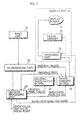
- FIG. 1 shows the relation between the Z values and regions of defocus relative to the focal point.
- several points, Za, Zb, Zc(focal point), Zd, and Ze, are fixed along the z coordinate, the direction in which an eye ray is aimed.
- the region of defocus of the sample point is determined as follows: Conditions Region of Defocus 1) Zd ⁇ Z>Zb none 2) Ze ⁇ Z>Zd or Zb ⁇ Z>Za 3 x 3 3) Z>Ze or Za ⁇ Z 5 x 5
- a square 501 represents a pixel corresponding to the sample point, while squares 502, 503 the regions of defocus under the conditions 1), 2), respectively.
- the mean intensity of the region of defocus a2 for the sample point a1 naturally includes the red intensity since a2 overlaps the pixels on the object's image. This causes the edge of the object to appear fuzzy and blurred, or the object to appear larger than it should in the image: a phenomenon that never occurs when seen through a camera. A similar phenomenon does occur even when the object is out of focus as long as there is the depth distance in the model.
- the present invention has a first object to provide an image defocusing apparatus capable of distributing no intensity (pixel value) on an object to its background in a defocused image whether the object is in focus or out of focus, and capable of computing an intensity distribution without decreasing the speed realised to date.
- the present invention has a second object to provide an image defocusing apparatus capable of forming the object's image of a size it should be in the defocused image.
- the present invention has a third object to provide an image defocusing apparatus capable of approximating a real lens's focusing effects on the defocused image.
- the present invention has a fourth object to provide an image defocusing apparatus capable of realising a depth distance corresponding to the Z value given to each pixel in the defocused image.
- the present invention has a fifth object to provide a rational method of defocusing an image applied to the above image defocusing apparatuses.
- an image defocusing apparatus for defocusing an image formed on a screen by modelling an object in a boundary box by updating pixel values on the image to approximate a lens's focusing effects
- the apparatus comprising: means for computing data related to a circle of confusion for each point in the boundary box, the circle of confusion being a measure how defocused an out-of-focus point is on the screen; means for selecting for a given target pixel reference pixels in the boundary box whose corresponding points' circles of confusion overlap the target pixel; and means for updating an original value of the target pixel by taking into account the values of the reference pixels and the data related to the target pixel's circle of confusion, said updating means including: a distributing unit for weighting a value of each reference pixel to determine a distribution within their own circles of confusion, the distribution being distributed to the target pixel; a target-pixel weighting unit for weighting the original value of the target pixel with the area of its circle of confusion; and an updating unit for
- the data related to the circle of confusion may comprise a radius and an area of each circle of confusion.
- the updating means may include an area calculating unit for computing an area of each circle of confusion using their respective radiuses C.
- the circle-of-confusion computing means may further include a storage unit for storing the radiuses C of the circles of confusion in relation with their respective pixels' x, y coordinates.
- the selecting means may include: a distance computing unit for computing a linear distance from the target pixel to each neighbouring pixel; a comparing unit for comparing the linear distance with the radius C relative to each neighbouring pixel by referring to their x, y co-ordinates; and a comparison result outputting means for selecting a neighbouring pixel whose radius C is longer than the linear distance, and subsequently outputting the selected neighbouring pixel as the reference pixel.
- the distributing unit may include a reference-pixel weighting unit for multiplying a value of each reference pixel by a reciprocal of an area of their respective circles of confusion.
- the selecting means may further include: a spatial-location comparing unit for comparing Z values of the target pixel and the reference pixels, the Z value representing a distance from the view point to their corresponding points; and the image defocusing apparatus may further comprise: means for disallowing the updating means from updating the original value of the target pixel when the reference pixel has a larger Z value than the target pixel.
- the selecting means may further include an output unit for comparing the Z values of the target pixel and the neighbouring pixels to select a neighbouring pixel whose Z value is smaller than the target pixel, and for subsequently outputting the selected neighbouring pixel to the distance computing unit, the Z value representing a distance from the view point to their corresponding points.
- the selecting means may comprise a first and a second selecting means and the updating means may comprise a first and a second updating means, the first selecting means being arranged to select a first reference pixel whose corresponding point's circle of confusion overlaps a target pixel in a first direction; the first updating means being arranged to update an original value of the target pixel by taking into account a value of the first reference pixel and the data related to the target pixel's circle of confusion; the second selecting means being arranged to select a second reference pixel whose corresponding point's circle of confusion overlaps the target pixel in a second direction, the second direction being orthogonal with respect to the first direction; and the second updating means being arranged to update the values updated by the first updating means by taking into account a value of the second reference pixel and the data related to the target pixel's circle of confusion.
- the data related to the circle of confusion may comprise a radius and an area of each circle of confusion.
- the updating means may include an area calculating unit for computing an area of each circle of confusion using their respective radiuses C.
- the circle-of-confusion computing means may further include a storage unit for storing the radiuses C of the circles of confusion in relation with their respective pixels' x, y coordinates.
- the first selecting means may include: a first distance computing unit for counting the number of pixels between the target pixel and each pixel aligned in an array that contains the target pixel in the first direction, the number thus counted being a distance; a first comparing unit for comparing the distance and the radius C relative to each pixel aligned in the target pixel's array in the first direction by referring to their x, y co-ordinates; a first comparison-result outputting unit for outputting a pixel aligned in the first direction whose radius C is longer than the distance to the first updating unit as the first reference pixel.
- the second selecting means may include: a second distance computing unit for counting the number of pixels between the target pixel and each pixel aligned in an array that contains the target pixel in the second direction, the number thus counted being a distance; a second comparing unit for comparing the distance and the radius C relative to each pixel aligned in the target pixel's array in the second direction by referring to their x, y co-ordinates; and a second comparison-result outputting unit for outputting a pixel aligned in the second direction whose radius C is longer than the distance to the second updating means as the second reference pixel.
- the distributing unit may include a first distributing unit for weighting a value of the first reference pixel to determine a distribution within their own circles of confusion, the distribution being distributed to the target pixel; and a second distributing unit for weighting a value of the second reference pixel to determine a distribution within their own circles of confusion, the distribution being distributed to the target pixel.
- the target-pixel weighting unit may include a first reference-pixel weighting unit associated with the first distribution unit for multiplying an original value of each reference pixel by a reciprocal of an area of their respective circles of confusion, and a second reference-pixel weighting unit associated with the second distribution unit for multiplying an original value of each reference pixel by a reciprocal of an area of their respective circles of confusion.
- the image defocusing apparatus may further comprise means for withholding the value of the target pixel updated by the first updating means to transfer them to the second updating means.
- the first selecting means may include a first spatial-location comparing means for comparing the Z values of the target pixel and the first reference pixel, the Z value representing a distance from the view point to their corresponding points.
- the second selecting means may include a second spatial-location comparing means for comparing the Z values of the target pixel and the second reference pixel.
- the first updating means may include a first disallowing unit for preventing the first updating means from updating the original value of the target pixel when the target pixel has a smaller Z value.
- the second updating means may include a second disallowing unit for preventing the second updating means from updating the original value of the target pixel when the target pixel has a smaller Z value.
- the first selecting means may further include a first output unit for comparing the Z values of the target pixel and the neighbouring pixels to select a neighbouring pixel whose Z value is smaller than the target pixel, and for subsequently outputting the selected neighbouring pixel to the first distance computing unit, the Z value representing a distance from the view point to their corresponding points.
- the second selecting means may further include a second output unit for comparing Z values of the target pixel and the neighbouring pixels to select a neighbouring pixel whose Z value is smaller than the target pixel, and for subsequently outputting the selected neighbouring pixel to the second distance computing unit.
- a method of defocusing an image by updating pixel values on the image formed on a screen by modelling an object in a boundary box comprising: computing data related to a circle of confusion for each point in the boundary box, the circle of confusion being a measure of how defocused an out-of-focus point is on the screen; for each target pixel, selecting reference pixels in the boundary box whose corresponding point's circle of confusion overlaps the target pixel; and updating an original value of the target pixel by taking into account the value of the reference pixel and the data related to the target pixel's circle of confusion, the updating step comprising weighting a value of each reference pixel to determine a distribution to the target pixel; computing an area of each overlapping circle of confusion and the target pixel's circle of confusion to weight the original value of the target pixel with the area of its circle of confusion; accumulating the distributions and the weighted value of the target pixel to yield a mean value, and updating the original
- the selecting step may include: computing a distance from the target pixel to each neighbouring pixel; comparing the distance with a radius C of the overlapping circle of confusion relative to each neighbouring pixel; selecting a neighbouring pixel whose radius C is longer than the distance as the reference pixel; selecting another target pixel; and repeating the above computing, comparing and selecting steps until all the pixels on the image have been selected as the target pixel.
- the image defocusing method may further comprise: comparing Z values of the target pixels and neighbouring pixels, the Z value representing a distance from a view point to their corresponding points, and preventing updating of the original value of the target pixel when the neighbouring pixel has a larger Z value than the target pixel.
- the second step may further comprise: comparing Z values of the target pixels and neighbouring pixels to select a neighbouring pixel whose Z value is smaller than the target pixel prior to computing the distance from the target pixel to each neighbouring pixel.
- the selecting step may comprise first and second selecting steps and the updating step may comprise first and second updating steps, the first selecting step comprising selecting a first reference pixel whose corresponding point's circle of confusion overlaps a target pixel along a first direction; the first updating step comprising updating an original value of the target pixel by taking into account a value of the first reference pixel and the data related to the target pixel's circle of confusion; the second step comprising selecting a second reference pixel whose corresponding point's circle of confusion overlaps the target pixel along a second direction, the second direction being orthogonal with respect to the first direction; and the second updating step comprising updating the value updated at the first updating step by taking into account a value of the second reference pixel and the data related to the target pixel's circle of confusion.
- the first and second selecting steps may respectively comprise: comparing Z values of the target pixels and neighbouring pixels, the Z value representing a distance from a view point to their corresponding points.
- the first and second updating steps may respectively comprise: preventing updating of the original value of the target pixel when the neighbouring pixel has a larger Z value than the target pixel.
- the first and second selecting steps may further and respectively comprise: comparing the Z values of the target pixels and neighbouring pixels to select a neighbouring pixel whose Z value is smaller than the target pixel prior to the comparing Z values step of the first and second selecting steps, respectively.
- data related to the circle of confusion of each pixel is computed by taking into account their respective Z values and the focal length and focal point of the lens being used.
- the colour intensity (pixel value) on the object in focus is not distributed to the background in the defocused image, preventing the object from appearing larger than it should.
- the colour intensity on the object out of focus is distributed according to the Z values and lens's focusing effects.
- the defocused image approximates the way they appear when seen through a camera.
- FIG. 3 shows a structure of an image defocusing apparatus in accordance with the first embodiment of the present invention.
- the image defocusing apparatus comprises an input unit 10, a display unit 20, a CG (computer graphics) processing unit 30, an image forming buffer 40, an original image saving buffer 50, and a defocus processing unit 100. Since the resulting defocused image is synthesized into a video taken by a video camera, lens's focusing effects must be taken into account at the time of defocusing. For this reason, data related to the optical characteristics of a lens being used, such as a zoom value, an iris value, a focal point, have been inputted into the defocus processing unit 100 in advance.
- the explanation of the structure and operation for the synthetic-image formation is omitted herein; for they are not the gist of the present invention.
- the input unit 10 is used to input data, such as geometric data, light source data, view point data, and image distance data into the CG processing unit 30.
- the details of the data are as follows: Geometric data Shape of an object to be modeled Light source data Location of a light source View point data Location of a view point, a view vector, and a viewing angle Image distance data Distance from the view point to an image
- the display unit 20 includes a display screen 21, a frame memory 22, and a switching device 23.
- the display screen 21 displays the data either in the frame memory 22 or the image forming buffer 40 under the control of the switching device 23 with a bank-switching command sent from the defocus processing unit 100.
- the CG processing unit 30 forms an original image of an object to be modelled by a process called "rendering" with the data from the input unit 10.
- the image forming process will be described in the following by referring to FIG. 4, although the explanation of the "rendering" is omitted.
- the CG processing unit 30 forms an object O1 at a focal length in a boundary box with the geometric data. Then, the CG processing unit 30 fixes a view point C1 at (0, 0, 0) in x, y, z co-ordinates with the view point data, while placing a screen S1 with the image distance data; C1 corresponds to a location of the video camera, and S1 is an image plane for the original image of the object O1. Accordingly, the CG processing unit 30 computes a Z value of each point for their respective corresponding pixels; the Z value represents a distance between C1 and each point in the z co-ordinate, the direction in which the video camera is aimed.
- the Z values given to pixels G1, G3 are the z co-ordinates of a point G2 on the object O1 and a point G4 on the background, respectively.
- the CG processing unit 30 removes hidden-surfaces using the Z values thus given, and outputs the resulting original image to the image forming buffer 40 first, and then saves the same in the original-image saving buffer 50.
- the CG processing unit 30 activates the defocus processing unit 100 by sending an operation-start command together with the Z values.
- the image forming buffer 40 receives the original image and stores values representing RGB intensities on each pixel, i.e., pixel values, of the original image in relation with their x, y coordinates.
- the original image of FIG. 4 is shown in FIG. 6A, and for the pixels within a rectangle d the image forming buffer 40 stores values as shown in FIG. 6B.
- Each rectangle in the grid represents the pixels, while the values in brackets the RGB intensities, and the rows and columns the x, y coordinates, respectively. Note that the original pixel values are updated by the values from the defocus processing unit 100.
- the original-image saving buffer 50 saves the original image in the same way as the image forming buffer 40.
- the defocus processing unit 100 forms a defocused image based on the original image with the Z values and optical characteristics of the lens.
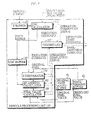
- the structure of the defocus processing unit 100 is depicted in FIG. 5.
- the defocus processing unit 100 comprises a Z buffer 101, a COC(circle of confusion) calculator 102, a COC buffer 103, a Z comparator 104, a RP(reference pixel) address calculator 105, a pixel value calculator 106, and a controller 107.
- the Z buffer 101 receives the Z value for each original pixel from the CG processing unit 30 and stores them in relation with their x, y coordinates. For the rectangle d in FIG. 6A, the Z buffer 101 stores the values as shown in FIG. 6C.
- the COC calculator 102 computes a radius C of a circle of confusion of each point for their corresponding pixels by Expression 1 as below with the Z value read out from the Z buffer 101 and the lens's optical characteristics data stored in advance.
- the circle of confusion is an out-of-focus point appearing as a circle rather than a point in the image, and is a measure of how defocused the out-of-focus point is.
- C
- the COC buffer 103 stores the radiuses C of the circles of confusion in relation with their x, y coordinates. For the rectangle d in FIG. 6A, the COC buffer 102 stores the values as shown in FIG. 6D.
- the Z comparator 104 reads out the original pixels from the image forming buffer 40 one by one as a target pixel, and selects the neighboring pixels for each target pixel.
- the neighboring pixels are the pixels such that satisfy
- the Z comparator 104 reads out the Z values of both the target and neighboring pixels from the Z buffer 101 using their x, y coordinates to select the neighboring pixels whose Z values are smaller than the target pixel.
- the neighboring pixels thus selected are outputted to the RP address calculator 105 and referred to as nominated pixels hereinafter.
- the RP address calculator 105 computes a distance between the target pixel and each nominated pixel while reading out the radius C of each nominated pixel from the COC buffer 103 using their x, y co-ordinates, and selects the ones whose radiuses C are longer than the computed distance.
- the nominated pixels thus selected are outputted to the pixel value calculator 106 and referred to as reference pixels hereinafter.
- FIG. 7B shows a set of the reference pixels for P23 selected in this way.
- the pixel value calculator 106 computes the distributions of the original values of the reference pixels within their own circles of confusion and a weighted value of the target pixel to yield a mean value. Accordingly, the pixel value calculator 106 updates the original pixel values in the image forming buffer 40 with the mean values. More precisely, the pixel value calculator 106 computes an area of the circle of confusion for each reference pixel using their respective radiuses C, and reads out the original pixel values for the reference pixels from the image saving buffer 50. Accordingly, the pixel value calculator 106 multiplies the summed original pixel values with a weight coefficient, i.e., the reciprocal of the area of their own circles of confusion, to compute the distributions.
- a weight coefficient i.e., the reciprocal of the area of their own circles of confusion
- the pixel value calculator 106 computes an area of the target pixel's circle of confusion, and reads out the original pixel value of the target pixel from the image saving buffer 50 to multiply the original pixel value with the reciprocal. Note that when the target pixel is in focus(exhibiting a 0-radius), the pixel value calculator 106 invariably gives a value 1 to the reciprocal.
- the controller 107 controls the above-described components by sending an execution command and receiving an operation-completion signal.
- the controller 107 activates the Z comparator 104 when it has received the operation-completion signal from the COC calculator 102, and likewise, the RP address calculator 105 from the Z comparator 104, the pixel value calculator 106 from the RP address calculator 105, and these descriptions are not repeated in the following.
- the controller 107 Upon the receipt of the operation-start command from the CG processing unit 30, the controller 107 activates the COC calculator 102.
- the COC calculator 102 then computes the radius C of the circle of confusion of each point in the boundary box for their respective pixels, and the computation results are stored into the COC buffer 103 in relation with their x, y coordinates(Steps 101-104).
- the controller 107 activates the Z comparator 104, so that it reads out one original pixel as the target pixel from the image forming buffer 40 and selects its neighboring pixels while reading out their Z values from the Z buffer 101 to select the nominated pixels(Steps 105-106).
- the controller 107 activates the RP address calculator 105, which correspondingly selects the reference pixels from the nominated pixels(Step 107). Accordingly, the controller 107 activates the pixel value calculator 106, which, in response, computes the distributions of the reference pixels within their own circles of confusion and the weighted value of the target pixel(Step 108), and further computes the mean value to update the original value of the target pixel(Step 109). Finally, the controller 107 checks whether all the original pixels in the image forming buffer 40 are read out as the target pixel or not(Step 110). If so, it issues the bank-switching command to the switching unit 23, so that the resulting defocused image in the image forming buffer 40 is displayed on the display screen 21 (Step 111); otherwise it returns to Step 105.
- FIG. 9 is a subroutine of Step 107, detailing the operation of the RP address calculator 105.
- the RP address calculator 105 receives the nominated pixels for the target pixel from the Z comparator 104(Step 201), and computes a distance between the target pixel and each nominated pixel(Step 202). Accordingly, the RP address calculator 105 compares the computed distance and the radius C of the circle of confusion of each nominated pixel to select the reference pixels(Steps 203-204), and checks whether it has received all the nominated pixels for the target pixel or not(205). If not, it returns to Step 201; otherwise it terminates the operation and sends the operation-completion signal to the controller 107.
- the points in focus do not appear in the circles of confusion, and thus their corresponding pixels are given the 0-radius, and left out from the nomination. Therefore, even when their corresponding pixels are overlapped by the circles of confusion of the neighboring out-of-focus points, their pixel values are not distributed within the overlapping circles of confusion. As a result, the points in focus appear clear and sharp while the out-of-focus points defocused correspondingly to their Z-values, enabling the object's edge to appear clear and sharp and in a size it should when the object is in focus.
- the neighboring pixels having larger Z values than the target pixel are excluded from the nominated pixels. However, they may be included in the reference pixels on the condition that the controller 107 disallows the pixel value calculator 106 to compute the distributions relative to these neighboring pixels.
- the defocus processing unit 100 may include a plurality of pixel value calculators 106 for parallel processing.
- An image defocusing apparatus in accordance with the second embodiment of the present invention is identical with that of the first embodiment except that the defocus processing unit 100 is replaced with a defocus processing unit 300.
- the Z comparator 104 is replaced with a first Z comparator 304 and a second Z comparator 308;
- the RP address calculator 105 is replaced with a first RP address calculator 305 and a second RP address calculator 309;
- the pixel value calculator 106 with a first pixel value calculator 306 and a second pixel value calculator 310;
- the controller 107 with a controller 311; and an IPV(intermediate pixel value) buffer 308 is additionally included.
- like components are labeled with like reference numerals with respect to the first embodiment, and the description of these components is not repeated.
- the first Z comparator 304 operates in the same way as the Z comparator 104 except that it outputs the nominated pixels to the first RP address calculator 305.
- the first RP address calculator 305 unlike the RP address calculator 105, selects the reference pixels within a certain range along the x coordinate; hence the reference pixels have radiuses C larger than the certain value. For example, when P03 in FIG. 7 is the target pixel, then the first RP address calculator 305 selects P04, P05 as the reference pixels as is shown in FIG. 11A; when P04, then P03, P05 in FIG. 11B; when P05, then P03, P04 in FIG. 11C. The reference pixels thus selected are outputted to the first pixel value calculator 305.
- the first pixel value calculator 306 computes the distributions of the reference pixels within their own circles of confusion and the weighted value of the target pixel, and further the mean value in the same way as the pixel value calculator 106.
- the value thus calculated is referred to as an intermediate pixel value hereinafter.
- the intermediate pixel value buffer 307 stores the intermediate pixel values in relation with their x, y coordinates.
- the second Z comparator 308 operates in the same way as the Z comparator 104 except that it outputs the nominated pixels to the second RP address calculator 309.
- the second RP address calculator 309 selects the reference pixels within a certain range along the y coordinate; hence the reference pixels have the radiuses C larger than the certain value. For example, when P03 in FIG. 7 is the target pixel, then the second RP address calculator 309 selects P13, P23, and P33 as the reference pixels as is shown in FIG. 12A; when P13, then P03, P23, and P33 in FIG. 12B; when P23, then P03, P13, P33 in FIG. 12C. The reference pixels thus selected are outputted to the second pixel value calculator 310.
- the second pixel value calculator 310 computes the distributions of the reference pixels within their own circles of confusion and the weighted value of the target pixel using the intermediate pixel values read out from the IPV buffer 307 in the same way as the pixel value calculator 106, and further computes the mean value.
- the value thus computed is referred to as the defocused pixel value hereinafter.
- the controller 311 controls the above-described components by sending the execution command and receiving the operation-completion signal in the same way as the controller 107.
- Steps 101 through 104 are identical with FIG. 8 in the first embodiment.
- the controller 311 Having received the notice of operation-completion signal from the COC calculator 102, the controller 311 activates the first Z comparator 304, which, in response, reads out one original pixel from the image forming buffer 40 and selects the neighboring pixels to further select the nominated pixels(Steps 305, 306).
- the controller 311 activates the first RP address calculator 305, which then selects the reference pixels from the nominated pixels relative to the value in the x-coordinate(Step 307).
- the controller 311 activates the first pixel value calculator 305, which computes the distributions of the reference pixels within their own circles of confusion and the weighted value of the target pixel, and further the mean value, i.e., the intermediate pixel value(Steps 308, 309).
- the controller 311 checks whether all the pixels in the image forming buffer 40 are read out as the target pixel or not(Step 310).
- Step 305 If not, it returns to Step 305; otherwise it activates the second Z comparator 308, which, in response, selects the neighboring pixels to further select the nominated pixels(Steps 311, 312). Subsequently, the controller 311 activates the second RP address calculator 310, which accordingly selects the reference pixels from the nominated pixels relative to the value in the y coordinate(Step 313). Subsequently, the controller 311 activates the second pixel value calculator 310, so that it computes the distributions of the reference pixels within their own circles of confusion and the weighted value of the target pixel by using the intermediate pixel values, and further the mean value, i.e., the distributed pixel value(Steps 314, 315).
- the controller 311 checks whether all the pixels in the image forming buffer 40 are read out as the target pixel(Step 316). If not, it returns to Step 311; otherwise, it issues the bank-switching command to the switching unit 23, so that the resulting defocused image in the image forming buffer 40 is displayed on the display screen 21 (Step 111)
- the reference pixels are selected faster than the first embodiment; the distance from the target pixel to each nominated pixel can be computed by simply counting the number of pixels between the two pixels in respective coordinates, instead of computing the root-square-mean value.
- first RP address calculator 305 may select the reference pixels relative to the value in y-coordinate, and the second RP address calculator 309 x-coordinate.
- the neighboring pixels having larger Z values than the target pixel are excluded from the nominated pixels. However, they may be included in the reference pixels on the condition that the controller 311 disallows the first and second pixel value calculators 306, 310 to compute the distributions relative to these neighbouring pixels.
Landscapes
- Physics & Mathematics (AREA)
- General Physics & Mathematics (AREA)
- Engineering & Computer Science (AREA)
- Theoretical Computer Science (AREA)
- Image Processing (AREA)
- Processing Or Creating Images (AREA)
- Image Generation (AREA)
- Image Analysis (AREA)
- Studio Devices (AREA)
Claims (23)
- Bild-Defokussiervorrichtung zum Defokussieren eines auf einem Bildschirm (S1) erzeugten Bildes durch Modellieren eines Objektes in einem Grenzkasten, indem Pixel-Werte auf dem Bild so aktualisiert werden, dass sich eine Näherung an die Fokussiereffekte einer Linse ergibt, wobei die Vorrichtung umfasst:wobei die sich auf den Konfusionskreis beziehenden Daten einen Radius und eine Fläche jedes Konfusionskreises umfassen, undeine Einrichtung (102), die sich auf einen Konfusionskreis beziehende Daten für jeden Punkt in dem Grenzkasten berechnet, wobei der Konfusionskreis ein Maß dafür ist, wie defokussiert ein nichtfokussierter Punkt auf dem Bildschirm (S1) ist;eine Einrichtung (105), die für ein vorgegebenes Ziel-Pixel Bezugs-Pixel in dem Grenzkasten auswählt, wobei die Konfusionskreise der entsprechenden Punkte derselben das Ziel-Pixel überlappen; undeine Einrichtung (106), die einen Ausgangswert des Ziel-Pixels aktualisiert, indem die Werte der Bezugs-Pixel und die sich auf den Konfusionskreis des Ziel-Pixels beziehenden Daten berücksichtigt werden, wobei die Aktualisierungseinrichtung enthält:eine Verteilungseinheit, die einen Wert jedes Bezugs-Pixels gewichtet und eine Verteilung in ihren eigenen Konfusionskreisen bestimmt, wobei die Verteilung auf das Ziel-Pixel verteilt wird;eine Ziel-Pixel-Gewichtungseinheit, die den Ausgangswert des Ziel-Pixels mit der Fläche seines Konfusionskreises gewichtet; undeine Aktualisierungseinrichtung, die die Verteilungen und den gewichteten Wert des Ziel-Pixels akkumuliert, um einen Mittelwert zu bestimmen, wobei der Ausgangswert des Ziel-Pixels durch den Mittelwert aktualisiert wird; und
wobei die Konfusionskreis-Berechnungseinrichtung (102) enthält:eine Radius-Errechungseinheit, die einen Radius C jedes Konfusionskreises berechnet, und wobei die Einrichtung, die einen Ausgangswert des Ziel-Pixels aktualisiert, des Weiteren eine Flächen-Errechnungseinheit enthält, die eine Fläche jedes Konfusionskreises unter Verwendung seines entsprechenden Radius C berechnet, und wobei die Einrichtung, die auswählt, enthält:eine Abstands-Berechnungseinheit, die einen linearen Abstand von dem Ziel-Pixel zu jedem benachbarten Pixel berechnet;eine Vergleichseinheit, die den linearen Abstand mit dem Radius C in Bezug auf jedes benachbarte Pixel unter Bezugnahme auf ihre x-, y-Koordinaten vergleicht;eine Vergleichsergebnis-Ausgabeeinrichtung, die benachbarte Pixel auswählt, deren Radius C größer ist als der lineare Abstand, und anschließend die ausgewählten benachbarten Pixel als die Bezugs-Pixel ausgibt. - Vorrichtung nach Anspruch 1, wobei die Radius-Errechnungseinheit den folgenden Ausdruck verwendet, um den Radius C jedes Konfusionskreises zu berechnen:
- Vorrichtung nach Anspruch 2, wobei die Konfusionskreis-Berechnungseinrichtung (102) des Weiteren eine Speichereinheit (103) enthält, die die Radien C der Konfusionskreise in Bezug auf die x-, y-Koordinaten ihrer entsprechenden Pixel speichert.
- Vorrichtung nach Anspruch 1, wobei die Verteilungseinheit eine Bezugs-Pixel-Gewichtungseinheit enthält, die einen Wert für jedes Bezugs-Pixel mit einem Reziproken einer Fläche ihrer entsprechenden Konfusionskreise multipliziert.
- Vorrichtung nach Anspruch 1, wobei die Auswähleinrichtung des Weiteren enthält:wobei die Bild-Defokussiervorrichtung (100) des Weiteren umfasst:eine Raumpositions-Vergieichseinheit, die Z-Werte des Ziel-Pixels und der Bezugs-Pixel vergleicht, wobei der Z-Wert einen Abstand von dem Betrachtungspunkt (C1) zu ihren entsprechenden Punkten darstellt, undeine Einrichtung, die verhindert, dass die Aktualisierungseinrichtung den Ausgangswert des Zielpixels aktualisiert, wenn das Bezugs-Pixel einen größeren Z-Wert hat als das Ziel-Pixel.
- Vorrichtung nach Anspruch 1, wobei die Auswähleinrichtung des Weiteren enthält:eine Ausgabeeinheit (104), die eine Einrichtung, die die Z-Werte des Ziel-Pixels und der benachbarten Pixel vergleicht und ein benachbartes Pixel auswählt, dessen Z-Wert kleiner ist als das Ziel-Pixel, sowie eine Einrichtung umfasst, die anschließend das ausgewählte benachbarte Pixel an die Abstands-Berechnungseinheit ausgibt, wobei der Z-Wert einen Abstand von dem Betrachtungspunkt (C1) zu ihren entsprechenden Punkten darstellt.
- Vorrichtung nach Anspruch 1, wobei die Auswähleinrichtung (105) eine erste und eine zweite Auswähleinrichtung (305, 309) umfasst, und die Aktualisierungseinrichtung (106) eine erste und eine zweite Aktualisierungseinrichtung (306 ,310) umfasst,
wobei die erste Auswähleinrichtung (305) ein erstes Bezugs-Pixel auswählt, wobei der Konfusionskreis des Punktes desselben ein Ziel-Pixel in einer ersten Richtung überlappt;
wobei die erste Aktualisierungseinrichtung (306) einen Ausgangswert des Ziel-Pixels aktualisiert, indem sie einen Wert des ersten Bezugs-Pixels und die sich auf den Konfusionskreis des Ziel-Pixels beziehenden Daten berücksichtigt;
wobei die zweite Auswähleinrichtung (309) ein zweites Bezugs-Pixel auswählt, wobei der Konfusionskreis des Punktes desselben das Ziel-Pixel in einer zweiten Richtung überlappt und die zweite Richtung rechtwinklig zu der ersten Richtung ist; und
die zweite Aktualisierungseinrichtung (310) die von der ersten Aktualisierungseinrichtung aktualisierten Werte aktualisiert, indem sie einen Wert des zweiten Bezugs-Pixels und die sich auf den Konfusionskreis des Ziel-Pixels beziehenden Daten berücksichtigt. - Vorrichtung nach Anspruch 7, wobei die Konfusionskreis-Berechnungseinrichtung (102) enthält:wobei p ein Abstand von einem Betrachtungspunkt (C1) zu einem Brennpunkt ist, d ein Z-Wert ist, der einen Abstand von dem Betrachtungspunkt (C1) zu jedem Punkt darstellt, f eine Brennweite ist und F ein Iris-Wert einer eingesetzten Linse ist, undeine Radius-Errechnungseinrichtung, die einen Radius C jedes Konfusionskreises unter Verwendung des folgenden Ausdrucks berechnet:
wobei die Aktualisierungseinrichtung (106, 306, 310) enthält:eine Flächen-Errechnungseinrichtung, die eine Fläche jedes Konfusionskreises unter Verwendung seines entsprechenden Radius C berechnet. - Vorrichtung nach Anspruch 8, wobei die Konfusionskreis-Berechnungseinrichtung (102) des Weiteren eine Speichereinheit (103) enthält, die die Radien C der Konfusionskreise in Bezug auf die x-, y-Koordinaten ihrer entsprechenden Pixel speichert.
- Vorrichtung nach Anspruch 9, wobei die erste Auswähleinrichtung (305) enthält:wobei die zweite Auswähleinrichtung (309) enthält:eine erste Abstands-Berechnungseinheit, die die Anzahl von Pixeln zwischen dem Ziel-Pixel und jedem Pixel, das in einer Anordnung, die das Ziel-Pixel enthält, in der ersten Richtung ausgerichtet ist, zählt, wobei es sich bei der so gezählten Zahl um einen Abstand handelt;eine erste Vergleichseinheit, die den Abstand und den Radius C in Bezug auf jedes Pixel, das in der Anordnung des Ziel-Pixels in der ersten Richtung ausgerichtet ist, unter Bezugnahme auf ihre x-, y-Koordinaten vergleicht;eine erste Vergleichsergebnis-Ausgabeeinrichtung, die ein in der ersten Richtung ausgerichtetes Pixel, dessen Radius größer ist als der Abstand, an die erste Aktualisierungseinrichtung als das erste Bezugs-Pixel ausgibt, undeine zweite Abstands-Berechnungseinrichtung, die die Anzahl von Pixeln zwischen dem Ziel-Pixel und jedem Pixel, das in einer Anordnung, die das Ziel-Pixel enthält, in der zweiten Richtung ausgerichtet ist, zählt, wobei es sich bei der so gezählten Anzahl um einen Abstand handelt;eine zweite Vergleichseinheit, die den Abstand und den Radius C in Bezug auf jedes Pixel, das in der Anordnung des Ziel-Pixels in der zweiten Richtung ausgerichtet ist, unter Bezugnahme auf ihre x-, y-Koordinaten vergleicht; undeine zweite Vergleichsergebnis-Ausgabeeinheit, die ein in der zweiten Richtung ausgerichtetes Pixel, dessen Radius größer ist als der Abstand, an die zweite Aktualisierungseinrichtung als das zweite Bezugs-Pixel ausgibt.
- Vorrichtung nach einem der Ansprüche 7 bis 10, wobei die Verteilungseinheit enthält:eine erste Verteilungseinheit, die einen Wert des ersten Bezugs-Pixels gewichtet, um eine Verteilung innerhalb ihrer eigenen Konfusionskreise zu bestimmen, wobei die Verteilung auf das Ziel-Pixel verteilt wird; und
eine zweite Verteilungseinheit, die einen Wert des zweiten Bezugs-Pixels gewichtet, um eine Verteilung innerhalb ihrer eigenen Konfusionskreise zu bestimmen, wobei die Verteilung auf die Ziel-Pixel verteilt wird. - Vorrichtung nach Anspruch 11, wobei die Ziel-Pixel-Gewichtungseinheit eine erste Bezugs-Pixel-Gewichtungseinheit, die mit der ersten Verteilungseinheit verbunden ist, und einen Ausgangswert jedes Bezugs-Pixels mit einem Reziproken einer Fläche ihrer entsprechenden Konfusionskreise multipliziert, und eine zweite Bezugs-Pixel-Gewichtungseinheit enthält, die mit der zweiten Verteilungseinheit verbunden ist, und einen Ausgangswert jedes Bezugspixels mit einem Reziproken einer Fläche ihrer entsprechenden Konfusionskreise multipliziert.
- Vorrichtung nach Anspruch 12, die des Weiteren umfasst:eine Einrichtung (307), die den Wert des Bezugs-Pixels, der durch die erste Aktualisierungseinrichtung (306) aktualisiert wird, zurückhält, um sie zu der zweiten Aktualisierungseinrichtung (310) zu übertragen.
- Vorrichtung nach Anspruch 11, wobei die erste Auswähleinrichtung (305) enthält:wobei die zweite Auswähleinrichtung (309) enthält:eine erste Raumpositions-Vergleichseinrichtung (304), die Z-Werte des Ziel-Pixels und des ersten Bezugs-Pixels vergleicht, wobei der Z-Wert einen Abstand von dem Betrachtungspunkt (C1) zu ihren entsprechenden Punkten darstellt, undwobei die erste Aktualisierungseinrichtung (306) enthält:eine zweite Raumpositions-Vergleichseinrichtung (308), die die Z-Werte des Ziel-Pixels und des zweiten Bezugs-Pixels vergleicht, undwobei die zweite Aktualisierungseinrichtung (310) enthält:eine erste Unterbindungseinheit, die verhindert, dass die erste Aktualisierungseinrichtung den Ausgangswert des Ziel-Pixels aktualisiert, wenn das Ziel-Pixel einen kleineren Z-Wert hat, undeine zweite Unterbindungseinheit, die verhindert, dass die zweite Aktualisierungseinrichtung (310) den Ausgangswert des Ziel-Pixels aktualisiert, wenn das Ziel-Pixel einen kleineren Z-Wert hat.
- Vorrichtung nach Anspruch 11, wobei die erste Auswähleinrichtung (305) des Weiteren enthält:wobei die zweite Auswähleinrichtung (309) des Weiteren enthält:eine erste Ausgabeeinheit, die die Z-Werte des Ziel-Pixels und der benachbarten Pixel vergleicht, und ein benachbartes Pixel auswählt, dessen Z-Wert kleiner ist als das Ziel-Pixel, und die anschließend das ausgewählte benachbarte Pixel an die erste Abstands-Berechnungseinheit ausgibt, wobei der Z-Wert einen Abstand von dem Betrachtungspunkt (C1) zu ihren entsprechenden Punkten darstellt, undeine zweite Ausgabeeinheit, die die Z-Werte des Ziel-Pixels und der benachbarten Pixel vergleicht, und ein benachbartes Pixel auswählt, dessen Z-Wert kleiner ist als das Ziel-Pixel, und die anschließend das ausgewählte benachbarte Pixel an die zweite Abstands-Berechnungseinheit ausgibt.
- Vorrichtung nach einem der vorangehenden Ansprüche, die des Weiteren wenigstens eine weitere Aktualisierungseinrichtung umfasst, die parallel zu der vorhandenen Aktualisierungseinrichtung angeordnet ist.
- Verfahren zum Defokussieren eines Bildes durch Aktualisieren von Pixel-Werten auf dem auf einem Bildschirm (S1) erzeugten Bild, indem ein Objekt in einem Grenzkasten moduliert wird, wobei das Verfahren umfasst:wobei der Berechnungsschritt umfasst:Berechnen (S102) von sich auf einen Konfusionskreis beziehenden Daten für jeden Punkt in dem Grenzkasten, wobei der Konfusionskreis ein Maß dafür ist, wie defokussiert ein nichtfokussierter Punkt auf dem Bildschirm (S1) ist;Auswählen von Bezugs-Pixeln in dem Grenzkasten für jedes Ziel-Pixel, deren entsprechender Konfusionskreis das Ziel-Pixel überlappt; undAktualisieren eines Ausgangswertes des Ziel-Pixels, indem der Wert des Bezugs-Pixels und die sich auf den Konfusionskreis des Ziel-Pixels beziehenden Daten aktualisiert werden, wobei der Aktualisierungsschritt umfasst:Gewichten eines Wertes jedes Bezugs-Pixels, um eine Verteilung auf das Ziel-Pixel zu bestimmen;Berechnen einer Fläche jedes überlappenden Konfusionskreises und des Konfusionskreises des Ziel-Pixels, um den Ausgangswert des Ziel-Pixels mit der Fläche seines Konfusionskreises zu gewichten;Akkumulieren der Verteilungen und des gewichteten Wertes des Ziel-Pixels, um einen Mittelwert zu erzeugen, und Aktualisieren des Ausgangswertes des Ziel-Pixels mit dem Mittelwert;Auswählen eines weiteren Ziel-Pixels; undWiederholen der oben aufgeführten Gewichtungs-, Berechnungs-, Akkumulierungsund Auswählschritte, bis alle Pixel als das Ziel-Pixel ausgewählt worden sind, undBerechnen eines Radius C jedes Konfusionskreises, und wobei der Auswählschritt umfasst:Berechnen eines Abstandes von dem Ziel-Pixel zu jedem benachbarten Pixel, Vergleichen des Abstandes mit einem Radius C des überlappenden Konfusionskreises in Bezug auf jedes benachbarte Pixel;Auswählen eines benachbarten Pixels, dessen Radius C größer ist als der Abstand des Bezugs-Pixels;Auswählen eines weiteren Ziel-Pixels; undWiederholen der oben aufgeführten Berechnungs-, Vergleichs- und Auswählschritte, bis alle Pixel auf dem Bild als das Ziel-Pixel ausgewählt worden sind.
- Verfahren nach Anspruch 17, wobei in dem Berechnungsschritt ein Radius C jedes Konfusionskreises unter Verwendung des folgenden Ausdrucks berechnet wird:
- Verfahren nach Anspruch 17, das des Weiteren umfasst:Vergleichen von Z-Werten der Ziel-Pixel und benachbarter Pixel, wobei der Z-Wert einen Abstand von einem Betrachtungspunkt (C1) zu ihren entsprechenden Punkten darstellt, undVerhindern der Aktualisierung des Ausgangswertes des Ziel-Pixels, wenn das benachbarte Pixel einen größeren Z-Wert hat als das Ziel-Pixel.
- Verfahren nach Anspruch 17, wobei der Auswählschritt des Weiteren umfasst:Vergleichen von Z-Werten der Ziel-Pixel und benachbarter Pixel, um ein benachbartes Pixel auszuwählen, dessen Z-Wert kleiner ist als das Ziel-Pixel, bevor der Abstand von dem Ziel-Pixel zu jedem benachbarten Pixel berechnet wird, wobei der Z-Wert einen Abstand von einem Betrachtungspunkt (C1) zu ihren entsprechenden Punkten darstellt.
- Verfahren nach Anspruch 17, wobei der Auswählschritt einen ersten und einen zweiten Auswählschritt umfasst und der Aktualisierungsschritt einen ersten und einen zweiten Aktualisierungsschritt umfasst,
wobei der erste Auswählschritt das Auswählen eines ersten Bezugs-Pixels umfasst,
wobei der Punkt des Konfusionskreises desselben ein Ziel-Pixel in einer ersten Richtung überdeckt;
der erste Aktualisierungsschritt das Aktualisieren eines Ausgangswertes des Ziel-Pixels, indem ein Wert des ersten Bezugs-Pixels und die sich auf den Konfusionskreis des Ziel-Pixels beziehenden Daten berücksichtigt werden, umfasst;
der zweite Auswählschritt das Auswählen eines zweiten Bezugs-Pixels umfasst,
wobei der Punkt des Konfusionskreises desselben das Ziel-Pixel in einer zweiten Richtung überlappt und die zweite Richtung rechtwinklig zu der ersten Richtung ist; und
der zweite Aktualisierungsschritt das Aktualisieren des in dem ersten Aktualisierungsschritt aktualisierten Wertes, indem ein Wert des zweiten Bezugs-Pixels und die sich auf den Konfusionskreis des Ziel-Pixels beziehenden Daten berücksichtigt werden, umfasst. - Verfahren nach Anspruch 21, wobei der erste und der zweite Auswählschritt jeweils umfassen:wobei der erste und der zweite Aktualisierungsschritt jeweils umfassen:Vergleichen von Z-Werten der Ziel-Pixel und benachbarter Pixel, wobei der Z-Wert einen Abstand von einem Betrachtungspunkt (C1) zu ihren entsprechenden Punkten darstellt, undVerhindern des Aktualisierens des Ausgangswertes des Ziel-Pixels, wenn das benachbarte Pixel einen größeren Z-Wert hat als das Ziel-Pixel.
- Verfahren nach Anspruch 22, wobei der erste und der zweite Auswählschritt des Weiteren jeweils umfassen:Vergleichen der Z-Werte der Ziel-Pixel und benachbarter Pixel, urn ein benachbartes Pixel auszuwählen, dessen Z-Wert kleiner ist als das Ziel-Pixel, vor den Schritten des Vergleichens von Z-Werten des ersten bzw. des zweiten Auswählschrittes.
Applications Claiming Priority (3)
| Application Number | Priority Date | Filing Date | Title |
|---|---|---|---|
| JP5015202A JP2792376B2 (ja) | 1993-02-02 | 1993-02-02 | 画像ぼかし処理装置 |
| JP1520293 | 1993-02-02 | ||
| JP15202/93 | 1993-02-02 |
Publications (2)
| Publication Number | Publication Date |
|---|---|
| EP0610080A1 EP0610080A1 (de) | 1994-08-10 |
| EP0610080B1 true EP0610080B1 (de) | 2002-07-17 |
Family
ID=11882287
Family Applications (1)
| Application Number | Title | Priority Date | Filing Date |
|---|---|---|---|
| EP94300793A Expired - Lifetime EP0610080B1 (de) | 1993-02-02 | 1994-02-02 | Bilddefokusierungsverfahren und -vorrichtung |
Country Status (4)
| Country | Link |
|---|---|
| US (1) | US5570433A (de) |
| EP (1) | EP0610080B1 (de) |
| JP (1) | JP2792376B2 (de) |
| DE (1) | DE69430962T2 (de) |
Cited By (1)
| Publication number | Priority date | Publication date | Assignee | Title |
|---|---|---|---|---|
| CN110866928B (zh) * | 2019-10-28 | 2021-07-16 | 中科智云科技有限公司 | 基于神经网络的目标边界分割及背景噪声抑制方法及设备 |
Families Citing this family (32)
| Publication number | Priority date | Publication date | Assignee | Title |
|---|---|---|---|---|
| GB9422089D0 (en) * | 1994-11-02 | 1994-12-21 | Philips Electronics Uk Ltd | Blurring for computer graphics |
| GB9616262D0 (en) * | 1996-08-02 | 1996-09-11 | Philips Electronics Nv | Post-processing generation of focus/defocus effects for computer graphics images |
| US6115078A (en) * | 1996-09-10 | 2000-09-05 | Dainippon Screen Mfg. Co., Ltd. | Image sharpness processing method and apparatus, and a storage medium storing a program |
| GB2325131B (en) * | 1997-03-27 | 2002-01-16 | British Broadcasting Corp | Improvements in artificial image generation |
| CA2239279C (en) * | 1997-06-02 | 2002-04-23 | Nippon Telegraph And Telephone Corporation | Image generating apparatus and method |
| KR100247938B1 (ko) * | 1997-11-19 | 2000-03-15 | 윤종용 | 영상처리 시스템의 디지탈 초점 조절방법 및 장치 |
| US6148113A (en) * | 1998-02-03 | 2000-11-14 | Micrografx, Inc. | System for stimulating the depth of field of an image in two dimensional space and method of operation |
| JP3668019B2 (ja) | 1998-10-27 | 2005-07-06 | 株式会社ソニー・コンピュータエンタテインメント | 記録媒体、画像処理装置および画像処理方法 |
| US6646687B1 (en) * | 1999-04-16 | 2003-11-11 | Ultimatte Corporation | Automatic background scene defocusing for image compositing |
| US6677948B1 (en) | 1999-06-14 | 2004-01-13 | Mitutoyo Corporation | Systems and methods for multi-resolution image defocusing |
| JP3980799B2 (ja) * | 1999-08-19 | 2007-09-26 | 株式会社リコー | 自動合焦装置およびその合焦方法 |
| JP3262772B2 (ja) | 1999-12-17 | 2002-03-04 | 株式会社ナムコ | 画像生成システム及び情報記憶媒体 |
| JP3448536B2 (ja) * | 1999-12-31 | 2003-09-22 | 株式会社スクウェア・エニックス | 三次元コンピュータ画像処理のプログラムを記録したコンピュータ読み取り可能な記録媒体、ぼかし描画処理方法およびビデオゲーム装置 |
| JP3404347B2 (ja) * | 2000-01-28 | 2003-05-06 | 株式会社スクウェア | 3次元コンピュータ画像処理のプログラムを記録したコンピュータ読み取り可能な記録媒体およびぼかし描画処理方法 |
| JP2001204964A (ja) * | 2000-01-28 | 2001-07-31 | Square Co Ltd | 球技用ゲームのプログラムを記録したコンピュータ読み取り可能な記録媒体および球技用ゲームの画像表示処理方法およびビデオゲーム装置 |
| US6618054B2 (en) | 2000-05-16 | 2003-09-09 | Sun Microsystems, Inc. | Dynamic depth-of-field emulation based on eye-tracking |
| AU2001264640A1 (en) * | 2000-05-16 | 2001-11-26 | Sun Microsystems, Inc. | Graphics system using a blur filter |
| US6292307B1 (en) * | 2000-06-28 | 2001-09-18 | Motorola, Inc. | Automatically focusing an optical instrument having a lens with only two focus positions |
| WO2002029718A2 (en) * | 2000-10-04 | 2002-04-11 | Sun Microsystems, Inc. | Dynamic depth-of-field emulation based on eye-tracking |
| EP1208897A1 (de) | 2000-11-21 | 2002-05-29 | Epcon Norge AS | Behälter zur kombinierten Entgasung und Flotation |
| JP3715222B2 (ja) | 2000-12-27 | 2005-11-09 | 株式会社ソニー・コンピュータエンタテインメント | 描画方法、描画装置、描画処理プログラム、描画処理プログラムを記録した記録媒体、および描画処理プログラム実行装置 |
| JP3748554B2 (ja) * | 2003-02-05 | 2006-02-22 | コナミ株式会社 | 画像生成装置、画像生成方法、及びプログラム |
| KR100617659B1 (ko) * | 2004-12-06 | 2006-08-28 | 엘지전자 주식회사 | 디지털 카메라 기기 및 아웃포커싱 처리 방법 |
| GB2431842B (en) * | 2005-10-28 | 2008-02-06 | Imagination Tech Ltd | Full screen anti-aliasing with dynamic filters |
| JP5481751B2 (ja) | 2010-05-27 | 2014-04-23 | 富士通株式会社 | 隠蔽処理プログラム、可視化処理方法及び装置 |
| EP2631871B1 (de) * | 2012-02-27 | 2015-07-01 | ST-Ericsson SA | Virtuelle Bilderzeugung |
| KR102125775B1 (ko) | 2014-02-24 | 2020-06-23 | 삼성전자주식회사 | 배제 픽셀 데이터를 보상하여 영상을 생성하는 방법 및 그것을 이용하는 영상 생성 장치 |
| US9905041B2 (en) * | 2014-11-24 | 2018-02-27 | Adobe Systems Incorporated | Depth of field synthesis using ray tracing approximation |
| US11935285B1 (en) | 2017-06-02 | 2024-03-19 | Apple Inc. | Real-time synthetic out of focus highlight rendering |
| US10482583B1 (en) * | 2018-05-10 | 2019-11-19 | Google Llc | Generating and displaying blur in images |
| US10992845B1 (en) | 2018-09-11 | 2021-04-27 | Apple Inc. | Highlight recovery techniques for shallow depth of field rendering |
| CN114489646A (zh) * | 2022-01-21 | 2022-05-13 | 深圳市雷鸟网络传媒有限公司 | 内容显示方法、装置和计算机可读存储介质 |
Family Cites Families (9)
| Publication number | Priority date | Publication date | Assignee | Title |
|---|---|---|---|---|
| JPS6314285A (ja) * | 1986-07-03 | 1988-01-21 | Fujitsu Ltd | 画像ぼかし処理方式 |
| JPS63259778A (ja) * | 1987-04-17 | 1988-10-26 | Hitachi Ltd | 画像デ−タの表示方法 |
| US5063375A (en) * | 1987-07-27 | 1991-11-05 | Sun Microsystems, Inc. | Method and apparatus for shading images |
| US5233472A (en) * | 1988-10-15 | 1993-08-03 | Asahi Kogaku Kogyo Kabushiki Kaisha | Method of controlling a zoom lens assembly |
| JP2809447B2 (ja) * | 1989-01-21 | 1998-10-08 | 株式会社リコー | 画像処理装置 |
| US5212516A (en) * | 1989-03-28 | 1993-05-18 | Canon Kabushiki Kaisha | Automatic focus adjusting device |
| JPH0336678A (ja) * | 1989-07-04 | 1991-02-18 | Fujitsu Ltd | 遠近感強調表示装置 |
| JP2728316B2 (ja) * | 1991-01-16 | 1998-03-18 | キヤノン株式会社 | レンズ位置制御装置を有する光学機器 |
| JP3089489B2 (ja) * | 1991-05-21 | 2000-09-18 | ソニー株式会社 | 画像データ処理装置 |
-
1993
- 1993-02-02 JP JP5015202A patent/JP2792376B2/ja not_active Expired - Lifetime
-
1994
- 1994-02-02 DE DE69430962T patent/DE69430962T2/de not_active Expired - Lifetime
- 1994-02-02 EP EP94300793A patent/EP0610080B1/de not_active Expired - Lifetime
-
1995
- 1995-10-13 US US08/542,543 patent/US5570433A/en not_active Expired - Lifetime
Cited By (1)
| Publication number | Priority date | Publication date | Assignee | Title |
|---|---|---|---|---|
| CN110866928B (zh) * | 2019-10-28 | 2021-07-16 | 中科智云科技有限公司 | 基于神经网络的目标边界分割及背景噪声抑制方法及设备 |
Also Published As
| Publication number | Publication date |
|---|---|
| US5570433A (en) | 1996-10-29 |
| DE69430962T2 (de) | 2002-11-07 |
| DE69430962D1 (de) | 2002-08-22 |
| JP2792376B2 (ja) | 1998-09-03 |
| EP0610080A1 (de) | 1994-08-10 |
| JPH06231273A (ja) | 1994-08-19 |
Similar Documents
| Publication | Publication Date | Title |
|---|---|---|
| EP0610080B1 (de) | Bilddefokusierungsverfahren und -vorrichtung | |
| US5949433A (en) | Processing image data | |
| KR0166066B1 (ko) | 영상 발생기 | |
| US4862388A (en) | Dynamic comprehensive distortion correction in a real time imaging system | |
| EP0680014B1 (de) | Verfahren und Vorrichtung zur Bildverarbeitung | |
| US5995111A (en) | Image processing apparatus and method | |
| KR101994121B1 (ko) | 중간 뷰로부터의 효율적인 캔버스 뷰 생성 | |
| EP0582875B1 (de) | Vorrichtung zur parallelen Bilderzeugung | |
| JP3320541B2 (ja) | 隣接する複数画像より画像を形成する画像処理方法及び装置 | |
| US5982342A (en) | Three-dimensional display station and method for making observers observe 3-D images by projecting parallax images to both eyes of observers | |
| CN101631219B (zh) | 图像修正装置、图像修正方法、投影仪以及投影系统 | |
| US20030184663A1 (en) | Apparatus, method, program and recording medium for image restoration | |
| US6249289B1 (en) | Multi-purpose high resolution distortion correction | |
| US20020180727A1 (en) | Shadow buffer control module method and software construct for adjusting per pixel raster images attributes to screen space and projector features for digital warp, intensity transforms, color matching, soft-edge blending, and filtering for multiple projectors and laser projectors | |
| JPH0627909A (ja) | データ投射システム | |
| EP0917106A2 (de) | Bildverarbeitungsgerät und Verfahren mit Polygonteilung | |
| US20030038811A1 (en) | System and method of line sampling object scene information | |
| GB2100556A (en) | Apparatus for generating successive picture frames depicting a feature to create an illusion of movement | |
| US5295199A (en) | Image transforming apparatus and method | |
| JP3328741B2 (ja) | エイリアス除去画像の表示装置 | |
| EP0248626B1 (de) | Videosignal-Verarbeitung | |
| Rolland et al. | A method of computational correction for optical distortion in head-mounted displays | |
| CN106791331B (zh) | 基于透镜阵列成像的图像处理方法、装置及成像系统 | |
| JP3058769B2 (ja) | 3次元画像生成方法 | |
| US5896134A (en) | Z buffer hidden surface removal device |
Legal Events
| Date | Code | Title | Description |
|---|---|---|---|
| PUAI | Public reference made under article 153(3) epc to a published international application that has entered the european phase |
Free format text: ORIGINAL CODE: 0009012 |
|
| AK | Designated contracting states |
Kind code of ref document: A1 Designated state(s): DE FR |
|
| 17P | Request for examination filed |
Effective date: 19950209 |
|
| 17Q | First examination report despatched |
Effective date: 19990108 |
|
| RIC1 | Information provided on ipc code assigned before grant |
Free format text: 6G 06T 5/20 A |
|
| GRAG | Despatch of communication of intention to grant |
Free format text: ORIGINAL CODE: EPIDOS AGRA |
|
| RIC1 | Information provided on ipc code assigned before grant |
Free format text: 7G 06T 5/20 A |
|
| GRAG | Despatch of communication of intention to grant |
Free format text: ORIGINAL CODE: EPIDOS AGRA |
|
| GRAH | Despatch of communication of intention to grant a patent |
Free format text: ORIGINAL CODE: EPIDOS IGRA |
|
| GRAH | Despatch of communication of intention to grant a patent |
Free format text: ORIGINAL CODE: EPIDOS IGRA |
|
| GRAA | (expected) grant |
Free format text: ORIGINAL CODE: 0009210 |
|
| AK | Designated contracting states |
Kind code of ref document: B1 Designated state(s): DE FR |
|
| REF | Corresponds to: |
Ref document number: 69430962 Country of ref document: DE Date of ref document: 20020822 |
|
| ET | Fr: translation filed | ||
| PLBE | No opposition filed within time limit |
Free format text: ORIGINAL CODE: 0009261 |
|
| STAA | Information on the status of an ep patent application or granted ep patent |
Free format text: STATUS: NO OPPOSITION FILED WITHIN TIME LIMIT |
|
| 26N | No opposition filed |
Effective date: 20030422 |
|
| REG | Reference to a national code |
Ref country code: DE Ref legal event code: R084 Ref document number: 69430962 Country of ref document: DE Effective date: 20111010 |
|
| PGFP | Annual fee paid to national office [announced via postgrant information from national office to epo] |
Ref country code: DE Payment date: 20130131 Year of fee payment: 20 Ref country code: FR Payment date: 20130301 Year of fee payment: 20 |
|
| REG | Reference to a national code |
Ref country code: DE Ref legal event code: R071 Ref document number: 69430962 Country of ref document: DE |
|
| PG25 | Lapsed in a contracting state [announced via postgrant information from national office to epo] |
Ref country code: DE Free format text: LAPSE BECAUSE OF EXPIRATION OF PROTECTION Effective date: 20140204 |