US6249289B1 - Multi-purpose high resolution distortion correction - Google Patents
Multi-purpose high resolution distortion correction Download PDFInfo
- Publication number
- US6249289B1 US6249289B1 US08/758,021 US75802196A US6249289B1 US 6249289 B1 US6249289 B1 US 6249289B1 US 75802196 A US75802196 A US 75802196A US 6249289 B1 US6249289 B1 US 6249289B1
- Authority
- US
- United States
- Prior art keywords
- distortion
- intermediate image
- mesh
- subdivided
- distortion mesh
- Prior art date
- Legal status (The legal status is an assumption and is not a legal conclusion. Google has not performed a legal analysis and makes no representation as to the accuracy of the status listed.)
- Expired - Lifetime
Links
Images


Classifications
-
- G—PHYSICS
- G06—COMPUTING; CALCULATING OR COUNTING
- G06T—IMAGE DATA PROCESSING OR GENERATION, IN GENERAL
- G06T15/00—3D [Three Dimensional] image rendering
- G06T15/005—General purpose rendering architectures
Definitions
- the present invention relates generally to computer graphics imagery, and more specifically, toward distortion correction in the display of computer generated imagery.
- Computer graphics applications often require the generation of complex three-dimensional surfaces (e.g., representing a car, a face, etc.) in world space. These complex three-dimensional surfaces are conventionally approximated with a mesh (or tessellation) of polygons (e.g., triangles). Generally, a polygon mesh is a collection of edges and vertices. An edge connects two vertices, and a polygon is a closed sequence of edges.
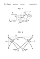
- FIG. 1 illustrates a projection of an object 104 in world space 106 to screen space 108 .
- an image generator uses Thales theorem in real time to produce the image exposed to an observer 102 .
- the projection transformation is applied to vertices because in Thales transformation, a straight line defined by a polygon edge in world space 106 , is transformed to a straight line defined by the polygon edge in screen space 108 .
- Thales theorem can be used to identify the distance H2 in screen space 108 .
- the image generator that projects objects in world space to a planar viewing window is referred to as a k*tan ⁇ image generator.
- the computed image generated by the k*tan ⁇ image generator can be directly displayed on a monitor or a behind-the-screen projection system as long as the projector is pointing in a direction that is perpendicular to the screen. If the projector is not pointing in a direction that is perpendicular to the screen, the displayed image becomes distorted and the picture produced by the projector may no longer appear rectangular.
- the trapezoidal distortion is handled directly by the projector.
- standard projectors cannot handle a lot of distortion.
- standard projectors also have problems with focal distance and brightness regularity.
- the trapezoidal distortion is handled by an image generator that modifies the projection law.
- Modification of a projection law becomes increasingly difficult when the screen is no longer flat (e.g., spherical).
- straight lines in world space are transformed into curved lines in screen space.
- the distortion can be corrected after the image has been generated by modifying the projector. This can be accomplished by adding specific hardware directly to the projector, or as a front end to the projector. In this process, a 2D distortion map is applied to the image produced by the image generator. This solution is acceptable for low levels of distortion.
- FIG. 2 illustrates a viewing pyramid that is made by joining the observer to the screen 210 , which for simplicity is .
- the image correction will have to produce two pixels out of only one that is computed by the image generator, thereby diminishing the resolution.
- distortion correction is performed by subdividing polygon edges.
- This functionality is usually incorporated into the heart of the pixel-processing system, thereby limiting its portability.
- a grid of distortion information is used to clip polygon edges.
- a polygon edge is cut into a plurality of segments defined by a plurality of vertices. The position of these vertices are adjusted to match the distortion.
- a drawback of this conventional method is the processing power required for implementation. The processing power required is substantially increased based upon the increased number of vertices created by the polygon edge subdivisions. This limits the ability to correct distortion on a per-pixel basis.
- the present invention satisfies the above mentioned needs by providing a distortion correction system and method that is programmable and does not rely on any projection system assumptions.
- the present invention uses a two-pass system.
- a field of view e.g., 180° ⁇ 180° half spherical screen
- the projection of polygons onto the subdivided viewports provides a first approximation to the distortion (i.e., a “facet-eye” view of the objects in world space).
- the second pass uses the intermediate images generated by each of the subdivided viewports in the first pass. These intermediate images are applied to a distortion mesh using a texture projection technique.
- the distortion mesh includes vertices that have texture coordinates representing pixels in a final distorted image.
- the resulting image produced by the mesh, covered with the texture of the intermediate images, represents the output image that is provided to a display generator.
- One advantage of the present invention is the ability for an observer to interactively adjust the initially defined distortion mesh based upon the viewing of the final output image. This process ensures that the distortion mesh accounts for all sources of distortion, even those that could not be identified in the initial system model. Specifically, a mouse or any other pointing device can be used to interactively adjust the perceived distortion correction thereby adjusting the vertices of the distortion mesh.
- FIG. 1 illustrates an exemplary projection of objects in world space to a flat screen.
- FIG. 2 illustrates a viewing pyramid
- FIG. 3 illustrates subdivided viewports represented by faces in a cube.
- FIGS. 4A and 4B illustrate a 180° ⁇ 180° field of view that is subdivided into three and five viewports.
- FIG. 5 illustrates the redefinition of a non-rectangular subdivided viewport.
- FIG. 6 illustrates an embodiment of the processing elements that are used to implement the second pass of the distortion correction process.
- FIG. 7 illustrates an example of a texture mapping process.
- FIG. 8 illustrates a mapping of vertices on a distortion mesh to pixels in a texture memory.
- FIG. 9 illustrates a flow chart of a parallel method of rendering viewports and copying the rendered viewports to texture memory.
- FIG. 10 illustrates an example of an application of a locally defined distortion mesh.
- FIG. 11 illustrates a block diagram of a computer useful for implementing elements of the present invention.
- the present invention provides a programmable solution to the distortion correction problem.
- This open solution does not rely on any projection system assumptions, thereby allowing distortion correction based upon inputs that include the type of projection system, the projector position, the projector's optical lens, the field of view, the observer perceived resolution, etc.
- the programmability of the system can also modify the distortion correction process to compensate in real-time for movement in the observer's position or switching from a first to a second observer position (e.g., different seats in a flight simulator).
- the present invention uses a two-pass system.
- an approximation to the distortion is generated using subdivided viewports.
- the resulting intermediate image is a “facet-eye” view of the objects in world space. The greater the number of subdivided viewports, the less approximated the result.
- the second pass uses the intermediate images generated by each of the subdivided viewports in the first pass. These intermediate images are applied to a distortion mesh using a texture projection technique. The resulting image produced by the distortion mesh, covered with the texture of the intermediate images, represents the output image that is provided to a display generator.
- the first pass approximates the distortion using one or more subdivided viewports. These viewports subdivide an observer's field of view. In the simple example of a 360° ⁇ 360° field of view (representing a completely spherical screen), six subdivided viewports can be used. These six subdivided viewports are represented by the six faces of a cube centered at the observer position O (see FIG. 3 ).
- a 180° ⁇ 180° field of view (representing half of a spherical screen) can be represented by three or five faces of the cube.
- the 180° ⁇ 180° field of view that is centered upon the direction from observer position O to vertice 301 .
- the field of view as the observer position moves to point 310 .
- This operation effectively “grows” the walls defined by vertices 301 - 302 - 303 - 304 (face A), 301 - 304 - 308 - 305 (face B), and 301 - 302 - 305 - 306 (face C) until only faces A, B and C are evident in the 180° ⁇ 180° field of view. This view is illustrated by FIG. 4 A.
- the cubic example described above was chosen for simplicity of illustration.
- inventive concepts of the present application are independent of the specific number and orientation of the subdivided viewports.
- the orientation and/or number of subdivided viewports can be chosen to provide a reasonably close approximation to a particular screen configuration.
- a general objective of the first pass is to ensure that enough resolution is available for the second pass.
- the first pass provides enough resolution to the second pass such that the second pass outputs no more than two pixels for only one pixel that is computed. A close approximation to the distortion is not required.
- the objects in the world space are then projected onto the plurality of subdivided viewports to identify the polygons that are viewed through individual viewports.
- the k*tan ⁇ projection of polygons in the world space is implemented using a 4 ⁇ 4 perspective projection matrix.
- This 4 ⁇ 4 perspective projection matrix can handle non-symmetric projections where a non-centered observer is not looking perpendicular to the viewport. This property of a 4 ⁇ 4 perspective projection matrix helps approximate the distortion problem with fewer viewports.
- 4 ⁇ 4 projection matrix used is implementation specific. Additional 4 ⁇ 4 projection matrices can be defined based upon linear affine transformations.
- One example is represented by the 4 ⁇ 4 perspective projection matrix identified by “OpenGL, Programming Guide”, Release 1, Addison-Wesley Publishing Company, 1995, p. 480.
- 4 ⁇ 4 matrix is applied to vertices in the homogeneous system (x, y, z, 1) giving (X, Y, Z, W)
- a clipping is done for vertices that are not in the [ ⁇ 1, 1] range on each dimension. This clipping process eliminates the polygons that are not projected onto the viewport of interest.
- Completion of the first pass is achieved after the projections onto the multiple subdivided viewports are effected.
- viewport mechanisms may be operative only on rectangular windows. With this limitation, some over covering and overlapping can occur. For example, consider the 180° ⁇ 180° view defined by the three faces A, B and C in FIG. 4 A. In this case, the three faces A, B and C are not rectangular. Accordingly, the viewport defined for each of faces A, B, and C are redefined to be rectangular.
- FIG. 5 illustrates the redefinition of subdivided viewport A.
- additional areas 502 and 504 are included as part of viewport A. Similar redefinitions of viewports B and C would also exist.
- Additional areas 502 and 504 are similarly involved in the first pass of the distortion correction process. In other words, objects in the world space are also projected onto areas 502 and 504 . Overlapping occurs since a single polygon may be projected onto more than one subdivided viewport. Over covering occurs since a polygon that otherwise would not have been projected onto any of the subdivided viewports is now projected onto an area similar to areas 502 and 504 . As will be described in greater detail below, the overlapping and over covering issues are handled by the dynamics of the second pass.
- FIG. 6 illustrates an embodiment of the elements that are used to implement the second pass of the distortion correction process. These elements are operative on the polygons of objects in the world space that can be projected onto one of the subdivided viewports defined in the first pass.
- the processing for each of the subdivided viewports comprises three initial processing steps.
- the polygons that can be projected onto the viewport are sent to geometry engine 602 (path 1 ). Note that a particular polygon will be sent to geometry engine 602 for each viewport upon which it is projected. Thus, a polygon may be sent to geometry engine 602 more than once. As described above, this situation can occur when subdivided viewports overlap due to the extension of originally non-rectangular viewports.
- the polygons for the viewport are rendered in 2D frame buffer 604 (path 2 ) to produce an intermediate image.
- the intermediate image i.e., rendered polygons
- the intermediate image in 2D frame buffer 604 is copied to texture memory 606 (path 3 ).
- a distortion mesh 610 is also sent to geometry engine 602 for rendering.
- distortion mesh 610 is a polygon mesh that models the distortion.
- Distortion mesh 610 can be static or generated in real-time.
- distortion mesh 610 can be a polygon mesh that is modeled in the shape of the screen (e.g., spherical, cylindrical, etc.).
- Distortion mesh 610 can also be defined in two dimensions. In this case, the two-dimensional distortion mesh represents a projected version of the three-dimensional mesh. In either case, each vertex of distortion mesh 610 has a texture coordinate that corresponds to a particular pixel in texture memory 606 . The mapping of pixels in texture memory 606 to vertices in distortion mesh 610 depends upon the observer position. This process is described in greater detail below.
- distortion mesh 610 is sent to geometry engine 602 (path 4 ) in a similar manner to the polygons in the subdivided viewports (path 1 ). Thereafter, distortion mesh 610 is rendered in 2D frame buffer 604 (path 5 ). Note that if distortion mesh 610 was originally defined as a two dimensional distortion mesh, the rendering of distortion mesh 610 is based upon an identity projection matrix. After distortion mesh 610 has been rendered in 2D frame buffer 604 (path 5 ), the intermediate texture images previously stored in texture memory 606 (path 3 ) are mapped onto the rendered distortion mesh (path 6 ).
- FIG. 7 illustrates an example of a texture mapping process.
- This process includes a series of spatial transformations.
- texture space 702 is transformed by a function f(u,v) onto a 3D surface 706 (x,y,z).
- This mapping process can be thought of as applying image detail to a surface, in much the same way as wallpaper.
- the image data that is mapped onto 3D surface 706 is subsequently projected by a function p(x,y,z) onto image plane 704 (i.e., screen space x,y) for display.
- the forward mapping function X and Y represents the composite function p(f(u,v)). Texture mapping is described in greater detail in G. Wolberg, “Digital Image Warping”, IEEE Computer Society Press, 3rd ed., 1994.
- a bilinear interpolation method is used to get a texture value out of texture memory 606 for each drawn pixel.
- bilinear interpolation utilizes a linear combination of the four closest pixel values to produce a new, interpolated value.
- Bilinear interpolations and related methods of spatial transformations are well known to those of ordinary skill in the relevant art.
- each vertex in distortion mesh 610 has a texture coordinate that corresponds to a pixel in texture memory 606 .
- FIG. 8 illustrates a top view of a cylindrical screen 830 .
- Cylindrical screen 830 is used for the projection of simulations that can be viewed by two observers A and B that are situated at observer locations 810 and 820 , respectively.
- the field of view is first subdivided into a plurality of viewports that include viewports 840 , 850 and 860 .
- Polygons projected onto each of viewports 840 , 850 and 860 are rendered and subsequently stored as intermediate images in texture memory 606 .
- the distortion mesh in the context of FIG. 8 is defined as a polygon mesh in the shape of screen 830 .
- an observer position must first be defined.
- vertex 812 on distortion mesh 830 corresponds to a pixel 802 that resides at or near the edges of viewports 840 and 850 .
- vertex 814 on distortion mesh 830 corresponds to a pixel 804 that resides at or near the edges of viewports 850 and 860 .
- the vertices on distortion mesh 830 that lie between vertices 812 and 814 will map to pixels that reside along the span between pixels 802 and 804 .
- vertex 822 on distortion mesh 830 corresponds to a pixel 802 that resides at or near the edges of viewports 840 and 850 .
- vertex 824 on distortion mesh 830 corresponds to a pixel 804 that resides at or near the edges of viewports 850 and 860 .
- the vertices on distortion mesh 830 that lie between vertices 822 and 824 will map to pixels that reside along the span between pixels 802 and 804 .
- a unique mapping can be defined for each unique observer position.
- the display of a distortion corrected image is valid for only a single observer at or near a single observer position. If an the observer moves within the projection system, the mapping can be redefined in real-time to alter the distortion correction process. Similarly, for the example of the two observers 810 and 820 , the display can be switched between two distortion correction states.
- the output image is completed.
- the output image is sent directly to display generator 608 (path 7 ) and then subsequently from display generator 608 to a projector (path 8 ).
- the projector may utilize only a portion of the output image.
- the projector having a “fisheye” lens for a ⁇ projection system will use only a circular portion of a rectangular output image.
- the process of rendering polygons projected in subdivided viewports and copying the rendered polygons to texture memory 606 can be done in parallel.
- This parallel process is illustrated in FIG. 9 .
- the polygons for a first subdivided viewport are rendered in 2D frame buffer 604 .
- steps 904 and 906 are performed in parallel.
- the polygons that have been rendered in step 902 are copied into texture memory 606 .
- the polygons projected into a second subdivided viewport are rendered in 2D frame buffer 604 . If the system determines at step 908 that there are more viewports to be processed, the system loops back to perform the parallel steps 904 and 906 again.
- Parallel steps 910 and 912 are analogous to parallel steps 904 and 906 .
- a rendered result is copied to texture memory 606 while another group of polygons are submitted to geometry engine 602 to be rendered.
- the rendered polygons of the last subdivided viewport are copied to texture memory 606
- the polygons of distortion mesh 610 are rendered. Note that distortion mesh 610 can be broken up into pieces and submitted sequentially for rendering. The rendered polygons of distortion mesh 610 are not copied to texture memory 606 .
- texture memory 606 is not distinct from frame buffer 604 . Accordingly, no copying of intermediate texture images is required from frame buffer 604 to texture memory 606 (path 3 ). The parallelism of steps 904 / 906 and 910 / 912 is therefore obviated.
- FIG. 9 illustrates a top view of a cylindrical projection system.
- the field of view is subdivided into multiple viewports comprising viewports 902 , 904 and 906 .
- the polygons projected into each of viewports 902 , 904 and 906 are rendered in frame buffer 604 .
- all rendered polygons that are part of the final output image are copied to texture memory 606 .
- the levels of distortion across the output image approximated by the first pass can vary significantly.
- the faceted view provided by the multiple subdivided viewports may acceptably approximate the actual distortion.
- the approximation is insufficient, thereby requiring the additional distortion correction provided by the second pass.
- areas 1010 and 1020 can individually require distortion correction beyond the first pass. Accordingly, a locally-defined distortion mesh can be created. This locally-defined distortion mesh can be defined in pieces and passed individually to geometry engine 602 . The remaining pieces of the distortion mesh, corresponding to portions of the output image that do not require further distortion beyond the first pass, are represented by holes in the distortion mesh.
- texture mapping of intermediate texture images are not applied to holes in the distortion mesh. Accordingly, the system does not need to copy the entire intermediate texture image of a subdivided viewport to texture memory 606 . Rather, only those portions of the intermediate texture image that correspond to the defined portions of the distortion mesh need to be copied to texture memory 606 . The portions of the intermediate texture image that correspond to the holes in the distortion mesh represent parts of the output image itself and do not need to be copied to texture memory 606 .
- the reduction in copying, rendering and texture mapping for the holes in the distortion mesh can greatly enhance the processing efficiency in real-time distortion correction applications. In the embodiment where texture memory 606 is incorporated as part of frame buffer 604 , processing efficiency is improved by the reduction in rendering and texture mapping for the holes in the distortion mesh.
- distortion correction is based upon numerous factors including the type of projection system, the projector position, the projector optical lens, the field of view, the observer perceived resolution, etc.
- Each of these individual effects can be accounted for initially based upon an analytical solution to the system model. In operation, however, each of the individual effects can deviate from the initial system model. For example, in a ⁇ projection system, the ideal position for the projector and the observer is at the center of the sphere. However, since both cannot occupy the same physical space, slight deviations from the ideal case necessarily occur. Similarly, imperfections in the projector lens cannot be accounted for in the system model.
- the present invention can account for these numerous deviations through an observer-based system tuning process.
- the observer interactively adjusts the distortion mesh based upon the viewing of the final output image. This process ensures that the distortion mesh accounts for all sources of distortion, even those that could not be identified in the initial system model. A complex process can therefore be reduced to a problem of user-driven optimization.
- test image This test image can be based upon a pattern of cubes defined in world space.
- the pattern of cubes should ideally be viewed by the observer, after distortion correction, as a symmetric grid pattern. Any significant imperfections in the initially defined distortion mesh 610 will result in obvious deviations in the grid pattern.
- a mouse or any other pointing device is used to interactively adjust the vertices of distortion mesh 610 .
- the mouse or equivalent pointing device is under control of the observer seated in the observer's position. The observer is able to select and move points on the screen that map to corresponding vertices of distortion mesh 610 . If distortion mesh 610 is defined as a two dimensional mesh, then the points on the screen can directly correspond to vertices on distortion mesh 610 . If distortion mesh 610 is defined as a three-dimensional mesh, on the other hand, the points on the screen correspond to vertices on distortion mesh 610 after an inverse mapping process. In either case, the observer is able to interactively adjust the distortion mesh to model the cumulative effect of all sources of distortion. This distortion correction process is clearly portable across various systems and applications.
- the invention may be implemented using hardware, software or a combination thereof and may be implemented in a computer system or other processing system.
- the invention is directed toward a computer system capable of carrying out the functionality described herein.
- An example computer system 1102 is shown in FIG. 11 .
- the computer system 1102 includes one or more processors, such as processor 1104 .
- the processor 1104 is connected to a communication bus 1106 .
- Various software embodiments are described in terms of this example computer system. After reading this description, it will become apparent to a person skilled in the relevant art how to implement the invention using other computer systems and/or computer architectures.
- Computer system 1102 also includes a main memory 1108 , preferably random access memory (RAM), and can also include a secondary memory 1110 .
- the secondary memory 1110 can include, for example, a hard disk drive 1112 and/or a removable storage drive 1114 , representing a floppy disk drive, a magnetic tape drive, an optical disk drive, etc.
- the removable storage drive 1114 reads from and/or writes to a removable storage unit 1118 in a well known manner.
- Removable storage unit 1118 represents a floppy disk, magnetic tape, optical disk, etc. which is read by and written to by removable storage drive 1114 .
- the removable storage unit 1118 includes a computer usable storage medium having stored therein computer software and/or data.
- secondary memory 1110 may include other means for allowing computer programs or other instructions to be loaded into computer system 1102 .
- Such means can include, for example, a removable storage unit 1122 and an interface 1120 .
- Examples of such can include a program cartridge and cartridge interface (such as that found in video game devices), a removable memory chip (such as an EPROM, or PROM) and associated socket, and other removable storage units 1122 and interfaces 1120 which allow software and data to be transferred from the removable storage unit 1118 to computer system 1102 .
- Computer system 1102 can also include a communications interface 1124 .
- Communications interface 1124 allows software and data to be transferred between computer system 1102 and external devices. Examples of communications interface 1124 can include a modem, a network interface (such as an Ethernet card), a communications port, a PCMCIA slot and card, etc.
- Software and data transferred via communications interface 1124 are in the form of signals which can be electronic, electromagnetic, optical or other signals capable of being received by communications interface 1124 .
- These signals 1126 are provided to communications interface via a channel 1128 .
- This channel 1128 carries signals 1126 and can be implemented using wire or cable, fiber optics, a phone line, a cellular phone link, an RF link and other communications channels.
- computer program medium and “computer usable medium” are used to generally refer to media such as removable storage device 1118 , a hard disk installed in hard disk drive 1112 , and signals 626 . These computer program products are means for providing software to computer system 1102 .
- Computer programs are stored in main memory and/or secondary memory 1110 . Computer programs can also be received via communications interface 1124 . Such computer programs, when executed, enable the computer system 1102 to perform the features of the present invention as discussed herein. In particular, the computer programs, when executed, enable the processor 1104 to perform the features of the present invention. Accordingly, such computer programs represent controllers of the computer system 1102 .
- the software may be stored in a computer program product and loaded into computer system 1102 using removable storage drive 1114 , hard drive 1112 or communications interface 1124 .
- the control logic when executed by the processor 1104 , causes the processor 1104 to perform the functions of the invention as described herein.
- the invention is implemented primarily in hardware using, for example, hardware components such as application specific integrated circuits (ASICs).
- ASICs application specific integrated circuits
- the invention is implemented using a combination of both hardware and software.
Abstract
Description

Claims (25)
Priority Applications (1)
| Application Number | Priority Date | Filing Date | Title |
|---|---|---|---|
| US08/758,021 US6249289B1 (en) | 1996-11-27 | 1996-11-27 | Multi-purpose high resolution distortion correction |
Applications Claiming Priority (1)
| Application Number | Priority Date | Filing Date | Title |
|---|---|---|---|
| US08/758,021 US6249289B1 (en) | 1996-11-27 | 1996-11-27 | Multi-purpose high resolution distortion correction |
Publications (1)
| Publication Number | Publication Date |
|---|---|
| US6249289B1 true US6249289B1 (en) | 2001-06-19 |
Family
ID=25050153
Family Applications (1)
| Application Number | Title | Priority Date | Filing Date |
|---|---|---|---|
| US08/758,021 Expired - Lifetime US6249289B1 (en) | 1996-11-27 | 1996-11-27 | Multi-purpose high resolution distortion correction |
Country Status (1)
| Country | Link |
|---|---|
| US (1) | US6249289B1 (en) |
Cited By (37)
| Publication number | Priority date | Publication date | Assignee | Title |
|---|---|---|---|---|
| JP2003009039A (en) * | 2001-06-27 | 2003-01-10 | Namco Ltd | Image display device, image display method, information storage medium, and image display program |
| US20030011535A1 (en) * | 2001-06-27 | 2003-01-16 | Tohru Kikuchi | Image display device, image displaying method, information storage medium, and image display program |
| FR2853827A1 (en) * | 2003-04-15 | 2004-10-22 | Ge Med Sys Global Tech Co Llc | Method for determining scale factor of patient's organ e.g. artery, involves placing patient on board between X-ray source and receiver, and determining two scaling factors determined at patient surface along path of X-rays across patient |
| US20050083531A1 (en) * | 2003-10-16 | 2005-04-21 | Millerd James E. | Calibration and error correction in multi-channel imaging |
| US20060001664A1 (en) * | 2004-04-19 | 2006-01-05 | Carbonera Carlos D | System and method for smoothing three dimensional images |
| US20070291233A1 (en) * | 2006-06-16 | 2007-12-20 | Culbertson W Bruce | Mesh for rendering an image frame |
| US20070291047A1 (en) * | 2006-06-16 | 2007-12-20 | Michael Harville | System and method for generating scale maps |
| US20080088528A1 (en) * | 2006-10-17 | 2008-04-17 | Takashi Shindo | Warp Image Circuit |
| US20110144785A1 (en) * | 2007-01-18 | 2011-06-16 | Carbonera Carlos D | System and method for generating instructions for customization |
| US20110213482A1 (en) * | 2010-02-25 | 2011-09-01 | Tim Saarela | Method for digital manufacturing of jewelry items |
| US8328365B2 (en) | 2009-04-30 | 2012-12-11 | Hewlett-Packard Development Company, L.P. | Mesh for mapping domains based on regularized fiducial marks |
| US20130135310A1 (en) * | 2011-11-24 | 2013-05-30 | Thales | Method and device for representing synthetic environments |
| US8515713B2 (en) | 2007-03-12 | 2013-08-20 | Jostens, Inc. | System and method for embellishment placement |
| USRE44696E1 (en) | 2002-12-10 | 2014-01-07 | Jostens, Inc. | Automated engraving of a customized jewelry item |
| US8766998B1 (en) * | 2008-08-22 | 2014-07-01 | Aechelon Technology, Inc. | Sampling of non-planar display surfaces |
| US20150287158A1 (en) * | 2014-04-05 | 2015-10-08 | Sony Computer Entertainment America Llc | Method for efficient re-rendering objects to vary viewports and under varying rendering and rasterization parameters |
| US9177533B2 (en) | 2012-05-31 | 2015-11-03 | Microsoft Technology Licensing, Llc | Virtual surface compaction |
| US9208265B2 (en) | 2011-12-02 | 2015-12-08 | Jostens, Inc. | System and method for jewelry design |
| US20150379697A1 (en) * | 2014-06-26 | 2015-12-31 | Daniel Pohl | Distortion meshes against chromatic aberrations |
| US20150379666A1 (en) * | 2014-06-27 | 2015-12-31 | Intel Corporation | Pixel-based warping and scaling accelerator |
| US9230517B2 (en) | 2012-05-31 | 2016-01-05 | Microsoft Technology Licensing, Llc | Virtual surface gutters |
| US9235925B2 (en) | 2012-05-31 | 2016-01-12 | Microsoft Technology Licensing, Llc | Virtual surface rendering |
| US9286122B2 (en) | 2012-05-31 | 2016-03-15 | Microsoft Technology Licensing, Llc | Display techniques using virtual surface allocation |
| US9307007B2 (en) | 2013-06-14 | 2016-04-05 | Microsoft Technology Licensing, Llc | Content pre-render and pre-fetch techniques |
| US9384711B2 (en) | 2012-02-15 | 2016-07-05 | Microsoft Technology Licensing, Llc | Speculative render ahead and caching in multiple passes |
| US9582615B2 (en) | 2013-01-16 | 2017-02-28 | Jostens, Inc. | Modeling using thin plate spline technology |
| USD789228S1 (en) | 2013-11-25 | 2017-06-13 | Jostens, Inc. | Bezel for a ring |
| WO2017120552A1 (en) * | 2016-01-06 | 2017-07-13 | Meta Company | Apparatuses, methods and systems for pre-warping images for a display system with a distorting optical component |
| CN107392988A (en) * | 2016-05-05 | 2017-11-24 | 辉达公司 | System, the method and computer program product for being used to render with variable sampling rate using perspective geometry distortion |
| RU2642350C1 (en) * | 2016-12-29 | 2018-01-24 | Самсунг Электроникс Ко., Лтд. | Imaging system (versions for implementation) |
| EP3322181A1 (en) * | 2016-11-11 | 2018-05-16 | Christie Digital Systems USA, Inc. | Method and system for screen correction |
| GB2565619A (en) * | 2017-08-15 | 2019-02-20 | Imagination Tech Ltd | Single Pass Rendering For Head Mounted Displays |
| JP2019099030A (en) * | 2017-12-06 | 2019-06-24 | 矢崎総業株式会社 | Display device for vehicle |
| US11120614B2 (en) * | 2017-09-07 | 2021-09-14 | Sony Interactive Entertainment Inc. | Image generation apparatus and image generation method |
| CN113949854A (en) * | 2021-11-17 | 2022-01-18 | 杭州震威科技有限公司 | Screen seamless display method and system based on distributed projection |
| US11436698B2 (en) * | 2020-01-28 | 2022-09-06 | Samsung Electronics Co., Ltd. | Method of playing back image on display device and display device |
| US20240020935A1 (en) * | 2022-07-15 | 2024-01-18 | The Boeing Company | Modeling system for 3d virtual model |
Citations (5)
| Publication number | Priority date | Publication date | Assignee | Title |
|---|---|---|---|---|
| US4695964A (en) * | 1983-12-02 | 1987-09-22 | Hitachi, Ltd. | Image correction processing method |
| US4862388A (en) * | 1986-12-15 | 1989-08-29 | General Electric Company | Dynamic comprehensive distortion correction in a real time imaging system |
| US5204944A (en) * | 1989-07-28 | 1993-04-20 | The Trustees Of Columbia University In The City Of New York | Separable image warping methods and systems using spatial lookup tables |
| US5278949A (en) * | 1991-03-12 | 1994-01-11 | Hewlett-Packard Company | Polygon renderer which determines the coordinates of polygon edges to sub-pixel resolution in the X,Y and Z coordinates directions |
| US5319744A (en) * | 1991-04-03 | 1994-06-07 | General Electric Company | Polygon fragmentation method of distortion correction in computer image generating systems |
-
1996
- 1996-11-27 US US08/758,021 patent/US6249289B1/en not_active Expired - Lifetime
Patent Citations (5)
| Publication number | Priority date | Publication date | Assignee | Title |
|---|---|---|---|---|
| US4695964A (en) * | 1983-12-02 | 1987-09-22 | Hitachi, Ltd. | Image correction processing method |
| US4862388A (en) * | 1986-12-15 | 1989-08-29 | General Electric Company | Dynamic comprehensive distortion correction in a real time imaging system |
| US5204944A (en) * | 1989-07-28 | 1993-04-20 | The Trustees Of Columbia University In The City Of New York | Separable image warping methods and systems using spatial lookup tables |
| US5278949A (en) * | 1991-03-12 | 1994-01-11 | Hewlett-Packard Company | Polygon renderer which determines the coordinates of polygon edges to sub-pixel resolution in the X,Y and Z coordinates directions |
| US5319744A (en) * | 1991-04-03 | 1994-06-07 | General Electric Company | Polygon fragmentation method of distortion correction in computer image generating systems |
Cited By (74)
| Publication number | Priority date | Publication date | Assignee | Title |
|---|---|---|---|---|
| JP2003009039A (en) * | 2001-06-27 | 2003-01-10 | Namco Ltd | Image display device, image display method, information storage medium, and image display program |
| US20030011535A1 (en) * | 2001-06-27 | 2003-01-16 | Tohru Kikuchi | Image display device, image displaying method, information storage medium, and image display program |
| USRE44696E1 (en) | 2002-12-10 | 2014-01-07 | Jostens, Inc. | Automated engraving of a customized jewelry item |
| FR2853827A1 (en) * | 2003-04-15 | 2004-10-22 | Ge Med Sys Global Tech Co Llc | Method for determining scale factor of patient's organ e.g. artery, involves placing patient on board between X-ray source and receiver, and determining two scaling factors determined at patient surface along path of X-rays across patient |
| US20050083531A1 (en) * | 2003-10-16 | 2005-04-21 | Millerd James E. | Calibration and error correction in multi-channel imaging |
| US7079251B2 (en) | 2003-10-16 | 2006-07-18 | 4D Technology Corporation | Calibration and error correction in multi-channel imaging |
| US20060001664A1 (en) * | 2004-04-19 | 2006-01-05 | Carbonera Carlos D | System and method for smoothing three dimensional images |
| US8085266B2 (en) * | 2004-04-19 | 2011-12-27 | Jostens, Inc. | System and method for smoothing three dimensional images |
| US20120075297A1 (en) * | 2004-04-19 | 2012-03-29 | Carbonera Carlos D | System and method for smoothing three dimensional images |
| US20070291047A1 (en) * | 2006-06-16 | 2007-12-20 | Michael Harville | System and method for generating scale maps |
| US7800628B2 (en) | 2006-06-16 | 2010-09-21 | Hewlett-Packard Development Company, L.P. | System and method for generating scale maps |
| US7854518B2 (en) * | 2006-06-16 | 2010-12-21 | Hewlett-Packard Development Company, L.P. | Mesh for rendering an image frame |
| US20070291233A1 (en) * | 2006-06-16 | 2007-12-20 | Culbertson W Bruce | Mesh for rendering an image frame |
| US20080088528A1 (en) * | 2006-10-17 | 2008-04-17 | Takashi Shindo | Warp Image Circuit |
| US20110144785A1 (en) * | 2007-01-18 | 2011-06-16 | Carbonera Carlos D | System and method for generating instructions for customization |
| US8473088B2 (en) | 2007-01-18 | 2013-06-25 | Jostens, Inc. | System and method for generating instructions for customization |
| US8515713B2 (en) | 2007-03-12 | 2013-08-20 | Jostens, Inc. | System and method for embellishment placement |
| US9434035B2 (en) | 2007-03-12 | 2016-09-06 | Jostens, Inc. | System and method for embellishment placement |
| US8766998B1 (en) * | 2008-08-22 | 2014-07-01 | Aechelon Technology, Inc. | Sampling of non-planar display surfaces |
| US8328365B2 (en) | 2009-04-30 | 2012-12-11 | Hewlett-Packard Development Company, L.P. | Mesh for mapping domains based on regularized fiducial marks |
| US9217996B2 (en) | 2010-02-25 | 2015-12-22 | Jostens, Inc. | Method for digital manufacturing of jewelry items |
| US8977377B2 (en) | 2010-02-25 | 2015-03-10 | Jostens, Inc. | Method for digital manufacturing of jewelry items |
| US20110213482A1 (en) * | 2010-02-25 | 2011-09-01 | Tim Saarela | Method for digital manufacturing of jewelry items |
| US20130135310A1 (en) * | 2011-11-24 | 2013-05-30 | Thales | Method and device for representing synthetic environments |
| US9208265B2 (en) | 2011-12-02 | 2015-12-08 | Jostens, Inc. | System and method for jewelry design |
| US9384711B2 (en) | 2012-02-15 | 2016-07-05 | Microsoft Technology Licensing, Llc | Speculative render ahead and caching in multiple passes |
| US9177533B2 (en) | 2012-05-31 | 2015-11-03 | Microsoft Technology Licensing, Llc | Virtual surface compaction |
| US10043489B2 (en) | 2012-05-31 | 2018-08-07 | Microsoft Technology Licensing, Llc | Virtual surface blending and BLT operations |
| US9959668B2 (en) | 2012-05-31 | 2018-05-01 | Microsoft Technology Licensing, Llc | Virtual surface compaction |
| US9230517B2 (en) | 2012-05-31 | 2016-01-05 | Microsoft Technology Licensing, Llc | Virtual surface gutters |
| US9235925B2 (en) | 2012-05-31 | 2016-01-12 | Microsoft Technology Licensing, Llc | Virtual surface rendering |
| US9286122B2 (en) | 2012-05-31 | 2016-03-15 | Microsoft Technology Licensing, Llc | Display techniques using virtual surface allocation |
| US9940907B2 (en) | 2012-05-31 | 2018-04-10 | Microsoft Technology Licensing, Llc | Virtual surface gutters |
| US9582615B2 (en) | 2013-01-16 | 2017-02-28 | Jostens, Inc. | Modeling using thin plate spline technology |
| US10542106B2 (en) | 2013-06-14 | 2020-01-21 | Microsoft Technology Licensing, Llc | Content pre-render and pre-fetch techniques |
| US9307007B2 (en) | 2013-06-14 | 2016-04-05 | Microsoft Technology Licensing, Llc | Content pre-render and pre-fetch techniques |
| US9832253B2 (en) | 2013-06-14 | 2017-11-28 | Microsoft Technology Licensing, Llc | Content pre-render and pre-fetch techniques |
| USD789228S1 (en) | 2013-11-25 | 2017-06-13 | Jostens, Inc. | Bezel for a ring |
| US10438312B2 (en) * | 2014-04-05 | 2019-10-08 | Sony Interactive Entertainment LLC | Method for efficient re-rendering objects to vary viewports and under varying rendering and rasterization parameters |
| EP3872767A1 (en) * | 2014-04-05 | 2021-09-01 | Sony Interactive Entertainment LLC | Method for efficient re-rendering objects to vary viewports and under varying rendering and rasterization parameters |
| US11748840B2 (en) | 2014-04-05 | 2023-09-05 | Sony Interactive Entertainment LLC | Method for efficient re-rendering objects to vary viewports and under varying rendering and rasterization parameters |
| EP3129958B1 (en) * | 2014-04-05 | 2021-06-02 | Sony Interactive Entertainment LLC | Method for efficient re-rendering objects to vary viewports and under varying rendering and rasterization parameters |
| US10915981B2 (en) * | 2014-04-05 | 2021-02-09 | Sony Interactive Entertainment LLC | Method for efficient re-rendering objects to vary viewports and under varying rendering and rasterization parameters |
| US20180047129A1 (en) * | 2014-04-05 | 2018-02-15 | Sony Interactive Entertainment America Llc | Method for efficient re-rendering objects to vary viewports and under varying rendering and rasterization parameters |
| US20150287158A1 (en) * | 2014-04-05 | 2015-10-08 | Sony Computer Entertainment America Llc | Method for efficient re-rendering objects to vary viewports and under varying rendering and rasterization parameters |
| WO2015154004A1 (en) | 2014-04-05 | 2015-10-08 | Sony Computer Entertainment America Llc | Method for efficient re-rendering objects to vary viewports and under varying rendering and rasterization parameters |
| US11423519B2 (en) * | 2014-06-26 | 2022-08-23 | Intel Corporation | Distortion meshes against chromatic aberrations |
| US20200051219A1 (en) * | 2014-06-26 | 2020-02-13 | Intel Corporation | Distortion meshes against chromatic aberrations |
| US20150379697A1 (en) * | 2014-06-26 | 2015-12-31 | Daniel Pohl | Distortion meshes against chromatic aberrations |
| CN106575433B (en) * | 2014-06-26 | 2021-03-09 | 英特尔公司 | Distortion reduction system and device |
| US10438331B2 (en) * | 2014-06-26 | 2019-10-08 | Intel Corporation | Distortion meshes against chromatic aberrations |
| US11748857B2 (en) | 2014-06-26 | 2023-09-05 | Intel Corporation | Distortion meshes against chromatic aberrations |
| CN106575433A (en) * | 2014-06-26 | 2017-04-19 | 英特尔公司 | Distortion meshes against chromatic aberrations |
| US9443281B2 (en) * | 2014-06-27 | 2016-09-13 | Intel Corporation | Pixel-based warping and scaling accelerator |
| US20150379666A1 (en) * | 2014-06-27 | 2015-12-31 | Intel Corporation | Pixel-based warping and scaling accelerator |
| US10565779B2 (en) | 2016-01-06 | 2020-02-18 | Meta View, Inc. | Apparatuses, methods and systems for pre-warping images for a display system with a distorting optical component |
| WO2017120552A1 (en) * | 2016-01-06 | 2017-07-13 | Meta Company | Apparatuses, methods and systems for pre-warping images for a display system with a distorting optical component |
| US10043305B2 (en) | 2016-01-06 | 2018-08-07 | Meta Company | Apparatuses, methods and systems for pre-warping images for a display system with a distorting optical component |
| CN107392988A (en) * | 2016-05-05 | 2017-11-24 | 辉达公司 | System, the method and computer program product for being used to render with variable sampling rate using perspective geometry distortion |
| US10102668B2 (en) * | 2016-05-05 | 2018-10-16 | Nvidia Corporation | System, method, and computer program product for rendering at variable sampling rates using projective geometric distortion |
| US9992464B1 (en) | 2016-11-11 | 2018-06-05 | Christie Digital Systems Usa, Inc. | Method and system for screen correction |
| EP3322181A1 (en) * | 2016-11-11 | 2018-05-16 | Christie Digital Systems USA, Inc. | Method and system for screen correction |
| RU2642350C1 (en) * | 2016-12-29 | 2018-01-24 | Самсунг Электроникс Ко., Лтд. | Imaging system (versions for implementation) |
| US10605968B2 (en) | 2016-12-29 | 2020-03-31 | Samsung Electronics Co., Ltd. | Imaging system |
| US10853988B2 (en) | 2017-08-15 | 2020-12-01 | Imagination Technologies Limited | Single pass rendering for head mounted displays |
| GB2565619B (en) * | 2017-08-15 | 2022-04-13 | Imagination Tech Ltd | Single Pass Rendering For Head Mounted Displays |
| GB2565619A (en) * | 2017-08-15 | 2019-02-20 | Imagination Tech Ltd | Single Pass Rendering For Head Mounted Displays |
| US11823317B2 (en) | 2017-08-15 | 2023-11-21 | Imagination Technologies Limited | Single pass rendering for head mounted displays |
| US11120614B2 (en) * | 2017-09-07 | 2021-09-14 | Sony Interactive Entertainment Inc. | Image generation apparatus and image generation method |
| JP2019099030A (en) * | 2017-12-06 | 2019-06-24 | 矢崎総業株式会社 | Display device for vehicle |
| US11436698B2 (en) * | 2020-01-28 | 2022-09-06 | Samsung Electronics Co., Ltd. | Method of playing back image on display device and display device |
| CN113949854A (en) * | 2021-11-17 | 2022-01-18 | 杭州震威科技有限公司 | Screen seamless display method and system based on distributed projection |
| CN113949854B (en) * | 2021-11-17 | 2022-06-24 | 杭州震威科技有限公司 | Screen seamless display method and system based on distributed projection |
| US20240020935A1 (en) * | 2022-07-15 | 2024-01-18 | The Boeing Company | Modeling system for 3d virtual model |
Similar Documents
| Publication | Publication Date | Title |
|---|---|---|
| US6249289B1 (en) | Multi-purpose high resolution distortion correction | |
| US6888544B2 (en) | Apparatus for and method of rendering 3D objects with parametric texture maps | |
| US5805782A (en) | Method and apparatus for projective texture mapping rendered from arbitrarily positioned and oriented light source | |
| El-Hakim et al. | A multi-sensor approach to creating accurate virtual environments | |
| Praun et al. | Lapped textures | |
| McReynolds et al. | Advanced graphics programming techniques using OpenGL | |
| US6437782B1 (en) | Method for rendering shadows with blended transparency without producing visual artifacts in real time applications | |
| US20150325044A1 (en) | Systems and methods for three-dimensional model texturing | |
| US7081895B2 (en) | Systems and methods of multi-pass data processing | |
| US6515674B1 (en) | Apparatus for and of rendering 3d objects with parametric texture maps | |
| US20130021445A1 (en) | Camera Projection Meshes | |
| US11625861B2 (en) | Point cloud colorization system with real-time 3D visualization | |
| US10924727B2 (en) | High-performance light field display simulator | |
| WO2000046754A1 (en) | Method and apparatus for cost effective digital image and video editing, using general 3d graphics pipeline | |
| US6369814B1 (en) | Transformation pipeline for computing distortion correction geometry for any design eye point, display surface geometry, and projector position | |
| US11570418B2 (en) | Techniques for generating light field data by combining multiple synthesized viewpoints | |
| US20030146922A1 (en) | System and method for diminished reality | |
| US9401044B1 (en) | Method for conformal visualization | |
| US6590574B1 (en) | Method, system, and computer program product for simulating camera depth-of-field effects in a digital image | |
| Popescu et al. | The depth discontinuity occlusion camera | |
| US6567085B1 (en) | Display techniques for three-dimensional virtual reality | |
| CA2709092A1 (en) | Smooth shading and texture mapping using linear gradients | |
| AU2017228700A1 (en) | System and method of rendering a surface | |
| JPH0721408A (en) | Illuminance calculating method for computer graphics and display device | |
| CA2258928A1 (en) | System and method for generating pixel values for pixels in an image using strictly deterministic methodologies for generating sample points |
Legal Events
| Date | Code | Title | Description |
|---|---|---|---|
| AS | Assignment |
Owner name: SILICON GRAPHICS, INC., CALIFORNIA Free format text: ASSIGNMENT OF ASSIGNORS INTEREST;ASSIGNORS:ARNAUD, REMI;CASTELLAR, JAVIER;JONES, MICHAEL T.;REEL/FRAME:008675/0980;SIGNING DATES FROM 19970218 TO 19970224 |
|
| STCF | Information on status: patent grant |
Free format text: PATENTED CASE |
|
| AS | Assignment |
Owner name: MICROSOFT CORPORATION, WASHINGTON Free format text: ASSIGNMENT OF ASSIGNORS INTEREST;ASSIGNOR:SILICON GRAPHICS, INC.;REEL/FRAME:012530/0133 Effective date: 20010928 |
|
| FPAY | Fee payment |
Year of fee payment: 4 |
|
| FPAY | Fee payment |
Year of fee payment: 8 |
|
| FPAY | Fee payment |
Year of fee payment: 12 |
|
| AS | Assignment |
Owner name: MICROSOFT TECHNOLOGY LICENSING, LLC, WASHINGTON Free format text: ASSIGNMENT OF ASSIGNORS INTEREST;ASSIGNOR:MICROSOFT CORPORATION;REEL/FRAME:034541/0001 Effective date: 20141014 |