EP0609520B1 - Perforator for metal plate - Google Patents
Perforator for metal plate Download PDFInfo
- Publication number
- EP0609520B1 EP0609520B1 EP93119680A EP93119680A EP0609520B1 EP 0609520 B1 EP0609520 B1 EP 0609520B1 EP 93119680 A EP93119680 A EP 93119680A EP 93119680 A EP93119680 A EP 93119680A EP 0609520 B1 EP0609520 B1 EP 0609520B1
- Authority
- EP
- European Patent Office
- Prior art keywords
- punch
- plate
- assembly
- die
- retaining
- Prior art date
- Legal status (The legal status is an assumption and is not a legal conclusion. Google has not performed a legal analysis and makes no representation as to the accuracy of the status listed.)
- Expired - Lifetime
Links
Images


Classifications
-
- B—PERFORMING OPERATIONS; TRANSPORTING
- B21—MECHANICAL METAL-WORKING WITHOUT ESSENTIALLY REMOVING MATERIAL; PUNCHING METAL
- B21D—WORKING OR PROCESSING OF SHEET METAL OR METAL TUBES, RODS OR PROFILES WITHOUT ESSENTIALLY REMOVING MATERIAL; PUNCHING METAL
- B21D37/00—Tools as parts of machines covered by this subclass
- B21D37/01—Selection of materials
-
- B—PERFORMING OPERATIONS; TRANSPORTING
- B21—MECHANICAL METAL-WORKING WITHOUT ESSENTIALLY REMOVING MATERIAL; PUNCHING METAL
- B21D—WORKING OR PROCESSING OF SHEET METAL OR METAL TUBES, RODS OR PROFILES WITHOUT ESSENTIALLY REMOVING MATERIAL; PUNCHING METAL
- B21D28/00—Shaping by press-cutting; Perforating
- B21D28/02—Punching blanks or articles with or without obtaining scrap; Notching
- B21D28/14—Dies
-
- B—PERFORMING OPERATIONS; TRANSPORTING
- B21—MECHANICAL METAL-WORKING WITHOUT ESSENTIALLY REMOVING MATERIAL; PUNCHING METAL
- B21D—WORKING OR PROCESSING OF SHEET METAL OR METAL TUBES, RODS OR PROFILES WITHOUT ESSENTIALLY REMOVING MATERIAL; PUNCHING METAL
- B21D28/00—Shaping by press-cutting; Perforating
- B21D28/02—Punching blanks or articles with or without obtaining scrap; Notching
- B21D28/16—Shoulder or burr prevention, e.g. fine-blanking
-
- B—PERFORMING OPERATIONS; TRANSPORTING
- B21—MECHANICAL METAL-WORKING WITHOUT ESSENTIALLY REMOVING MATERIAL; PUNCHING METAL
- B21D—WORKING OR PROCESSING OF SHEET METAL OR METAL TUBES, RODS OR PROFILES WITHOUT ESSENTIALLY REMOVING MATERIAL; PUNCHING METAL
- B21D45/00—Ejecting or stripping-off devices arranged in machines or tools dealt with in this subclass
- B21D45/003—Ejecting or stripping-off devices arranged in machines or tools dealt with in this subclass in punching machines or punching tools
- B21D45/006—Stripping-off devices
-
- Y—GENERAL TAGGING OF NEW TECHNOLOGICAL DEVELOPMENTS; GENERAL TAGGING OF CROSS-SECTIONAL TECHNOLOGIES SPANNING OVER SEVERAL SECTIONS OF THE IPC; TECHNICAL SUBJECTS COVERED BY FORMER USPC CROSS-REFERENCE ART COLLECTIONS [XRACs] AND DIGESTS
- Y10—TECHNICAL SUBJECTS COVERED BY FORMER USPC
- Y10T—TECHNICAL SUBJECTS COVERED BY FORMER US CLASSIFICATION
- Y10T83/00—Cutting
- Y10T83/04—Processes
- Y10T83/06—Blanking
-
- Y—GENERAL TAGGING OF NEW TECHNOLOGICAL DEVELOPMENTS; GENERAL TAGGING OF CROSS-SECTIONAL TECHNOLOGIES SPANNING OVER SEVERAL SECTIONS OF THE IPC; TECHNICAL SUBJECTS COVERED BY FORMER USPC CROSS-REFERENCE ART COLLECTIONS [XRACs] AND DIGESTS
- Y10—TECHNICAL SUBJECTS COVERED BY FORMER USPC
- Y10T—TECHNICAL SUBJECTS COVERED BY FORMER US CLASSIFICATION
- Y10T83/00—Cutting
- Y10T83/929—Tool or tool with support
- Y10T83/9411—Cutting couple type
- Y10T83/9423—Punching tool
- Y10T83/9428—Shear-type male tool
Definitions
- the present invention relates to an assembly comprising a metal plate and an apparatus for forming a hole in said metal plate of the type as defined in the preamble of claim 1.
- Assemblies for hole forming by punching are widely known in the art, for instance from US-A-2,763,325 which shows an assembly of the type as defined in the preamble of claim 1.
- the known assembly includes a punch means and die means co-operating with each other.
- the effective end of the punch means has a diameter corresponding to the diameter of the hole to be formed. Requirements with respect to the surface quality and clearance are neither mentioned to be important nor described by specific features.
- JP-A-63-203 223 describes an apparatus for coating the surface of a base metal used for forming punch means by a ceramic coating.
- the punch means coated is not described.
- a lithographic printing system is generally operated by utilising a presentized plate (herein referred to as a PS plate), which comprises a support consisting of a thin metal plate of e.g. aluminium or steel.
- a PS plate which comprises a support consisting of a thin metal plate of e.g. aluminium or steel.
- Such a PS plate processed for lithography is mounted in a printer.
- the PS plate is provided with punched holes to receive positioning members.
- a perforator is used for punching the plate material.
- the perforator is a moveable blade or punch shaped to punch a hole in order to pierce the plate material, and a stationary blade or die for slidably receiving the punch.
- the plate material is continuous or is a separate piece and is sandwiched between the punch and the die so as to punch holes in the plate material.
- Such a perforator is usable to punch simultaneously plural superposed pieces of material.
- the punch and die should be sufficiently hard, should have each blade precisely constructed, and should have sufficiently small roughness on the faces of the blades. It is usual to form the punch from high speed steel SKH, and to form the die from special tool steel SKD, and to set the roughness on the blade faces to be 2,0 ⁇ m, preferably as small as 1.0 ⁇ m. It is general to provide clearance between the punch and the die, of 5 to 8% of the thickness of the plate material to be punched.
- an object of the present invention is to provide an assembly comprising a metal plate and an apparatus for forming an hole in said metal plate of high performance and great durability, avoiding the need for unwanted disposal of industrial waste.
- the punch means and/or die means is coated with non-crystalline hard carbon having a surface roughness as low as 0.8 ⁇ m or less.
- the clearance between the punch means and the die means is up to 10 to 30% of the thickness of the plate material.
- Each advancing end of the punch means is provided with a cylindrical tip portion having a reduced width.
- the retaining means is provided with cushioning material mounted for contact with the plate material.
- This assembly has high performance during perforating operations and durability over long use. Even when the punching operation is repeated, there is little dust generated from the plate material. No irregularities appear along the punched edges of the punched holes. Even after the punches are raised and removed from the punched holes, no unwanted raised edges or folds around the punched holes are generated, even upon repeated use of the novel perforator. The quality of PS plates as products is maintained without decreasing.
- the use of the perforator does not require frequent inspection or cleaning of the blade faces. Efficiency of punching is greatly improved.
- the sheet perforator has a drive mechanism 10 including a motor.
- a punch holder 12 is connected via a pair of guiding rods 13 to the drive mechanism 10, and is drivable to move up and down.
- On the punch holder 12 are arranged a number of, e.g. seven, punches 14 extending downward and formed e.g. from high speed steel SKH.
- a transport mechanism 9 (see Fig. 3) transports a rectangular thin flat metal sheet 15, and inserts it under the punches 14.
- the metal sheet 15 is placed on a die array 16 formed e.g. from special tool steel SKD.
- the punches 14 arc inserted into the die array 16, until the punches 14 and the die array 16 cut the metal sheet 15 to form punch holes shaped to be round or elliptical.
- the die array 16 has die holes 16a whose inner diameter or width is substantially equal to the width of the punch 14.
- the metal sheet 15 is punched when the die holes 16a receive the advancing punches 14.
- the die array 16 is supported on a die holder 17. After the metal sheet 15 is punched, the waste bits of the metal sheet 15 are discharged through openings 1 7a.
- a stripper plate 18 is disposed fixedly on the die array 16. The metal sheet 15 is inserted between the stripper plate 18 and the die array 16. When the punch holder 12 is raised after punching the metal sheet 15, the stripper plate 18 contacts the metal sheet 15, separates the rising punches 14 from the metal sheet 15, and keeps the metal sheet 15 from rising with the punches 14.
- the bottom of the stripper plate 18 has a cushioning material 19 for contact with the metal sheet 15.
- the cushioning material 19 consists of a sheet of polyethylene terephthalate (PET) 170 ⁇ m thick. Note that, after the punches 14 are retracted from the metal sheet 15, the transport mechanism 9 moves the metal sheet 15 from between the die array 16 and the punches 14.
- the metal sheet 15 is constituted of a PS plate 15a and a light-shielding lining sheet 15b attached thereto.
- a punching blade edge 14a around the punches 14, the top face of the die array 16, and the inside of the die holes 16a is coated with non-crystalline hard carbon.
- the punches 14 or the die array 16 may lack such a coating, it is preferred to coat both.
- the roughness of the carbon coat of those faces is 0.8 ⁇ m or less. As illustrated in Figs.
- the punches 14 each have a stepped tip portion 14b shaped as a cylinder smaller in diameter than the main body of the punch, thereby reducing the distortion or unwanted raised margin about the punched hole.
- the height H of the tip portion 14b is at least half the thickness of the metal sheet 15, and at most twice that thickness.
- the clearance C as shown is half of the difference between diameters of the punch 14 and the die hole 16a, and is in the range of 10 to 30% of the thickness of the metal sheet 15. Note that the perforator may lack the transport mechanism 9 and instead be fed manually.
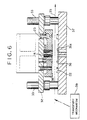
- Fig. 6 illustrates a preferred web perforator, in which a continuous web 35 constituted of PS plate and light-shielding lining paper is repeatedly punched in synchronism with the intermittent progressive conveyance of the web 35 by a transport mechanism 39. Elements similar to those of the sheet perforator in Figs. 1 and 2 are designated with the identical numerals.
- a stripper plate 38 is slidably mounted on a punch holder 32. When the punch holder 32 Is lowered, the stripper plate 38 comes into contact with a stopper 22. Subsequently, the punch holder 32 is lowered against the bias of a stripper spring 23, until the punches 14 punch the web 35. After punching, the punch holder 32 with the punches 14 Is raised, and the stripper plate 38 is raised.
- reference numeral 33 designates guiding rods, 36 a die array, and 37 a die holder.
- the punches and die array to be used in the present invention can be formed, not only from the high speed steel SKH or the special tool steel SKD above described, but from sufficiently hard other steels, such as various high speed steels and high speed steel powder. It is also possible to construct punches differently: the punch 25 in Fig. 7 has a conical tip portion 25a; the punch 26 in Fig. 8 has a truncated conical tip portion 26a; and the punch 27 in Fig. 9 has a quadrangular stepped tip portion 27a.
- punched holes formed in the above embodiments are round, alternatively punched holes shaped like slots having round corners can be formed, by use of punches shaped correspondingly.
- the metal sheets and web constitute PS aluminum plates in the above embodiment, the present invention is applicable to punching PS steel plates.
Description
- The present invention relates to an assembly comprising a metal plate and an apparatus for forming a hole in said metal plate of the type as defined in the preamble of claim 1.
- Assemblies for hole forming by punching are widely known in the art, for instance from US-A-2,763,325 which shows an assembly of the type as defined in the preamble of claim 1. The known assembly includes a punch means and die means co-operating with each other. The effective end of the punch means has a diameter corresponding to the diameter of the hole to be formed. Requirements with respect to the surface quality and clearance are neither mentioned to be important nor described by specific features.
- JP-A-63-203 223 describes an apparatus for coating the surface of a base metal used for forming punch means by a ceramic coating. The punch means coated, however, is not described.
- A lithographic printing system is generally operated by utilising a presentized plate (herein referred to as a PS plate), which comprises a support consisting of a thin metal plate of e.g. aluminium or steel. Such a PS plate processed for lithography is mounted in a printer. To position the PS plate precisely in the printer, the PS plate is provided with punched holes to receive positioning members.
- In a manufacturing process for such PS plates, a perforator is used for punching the plate material. The perforator is a moveable blade or punch shaped to punch a hole in order to pierce the plate material, and a stationary blade or die for slidably receiving the punch. The plate material is continuous or is a separate piece and is sandwiched between the punch and the die so as to punch holes in the plate material. Such a perforator is usable to punch simultaneously plural superposed pieces of material.
- Good formation of punch holes which will he stable even after long use requires high quality of the punch and die of the perforator: the punch and die should be sufficiently hard, should have each blade precisely constructed, and should have sufficiently small roughness on the faces of the blades. It is usual to form the punch from high speed steel SKH, and to form the die from special tool steel SKD, and to set the roughness on the blade faces to be 2,0 µm, preferably as small as 1.0 µm. It is general to provide clearance between the punch and the die, of 5 to 8% of the thickness of the plate material to be punched.
- In the course of repeated punching, finely powdered aluminum dust is generated from the plate material. The fine dust sticks on the blade faces, degrades the sharpness of the punching structure, and causes the punched edges to have irregularities, which are raised over the plate surface by contact with the punches when the punches are raised and removed from the punch holes. In view of this problem, it is proposed in Japanese Patent Laid-Open Publ. No. 61-241096 to superpose the metal plate material on light-shielding polyethylene-laminated lining paper and to punch the plate material from the side of the lining paper. The use of the polyethylene-laminated lining paper is somewhat effective in maintaining the sharpness of the punching structure, because the lining paper can wipe the fine dust off the blade faces.
- Widespread use of polyethylene-laminated lining paper, however, could he harmful when discarded as industrial waste. Moreover, the mass production of PS plates can be counterproductive, In view of the public concern now shown for protection of the global environment against destruction caused by considerable wastes.
- It might be better, for protecting PS plates from ambient light, to use polyethylene lining paper superposed on the PS plates. An experiment was conducted with thin aluminum plate with which polyethylene lining paper was used and which is 150 µm thick. The SKH-formed punches and/or the SKD-formed die had a roughness of 1.0 to 2.0 µm. A
round punch hole 2 formed by the punches of a sheet perforation was 4 mm across, as illustrated in Fig. 10. In Fig. 11, a slot-like punch hole 3, formed by punches of a web perforator moving in the arrowed direction, was 10 mm long and 6 mm wide. - It has been observed that 10 to 20 times of operation of punching the plate material resulted in generation of an
unwanted rise 5 or fold 6 aroundpunch holes punch holes punch holes - The use of such conventional perforators, after every 10 to 20 punching operations, requires inspection or cleaning of the blade faces. A problem lies in that there is a considerable limit to improving efficiency in punching out plate material.
- In view of the foregoing problems, an object of the present invention is to provide an assembly comprising a metal plate and an apparatus for forming an hole in said metal plate of high performance and great durability, avoiding the need for unwanted disposal of industrial waste.
- In order to achieve the above and other objects and advantages of this invention, the assembly of claim 1 is provided.
- The punch means and/or die means is coated with non-crystalline hard carbon having a surface roughness as low as 0.8 µm or less. The clearance between the punch means and the die means is up to 10 to 30% of the thickness of the plate material. Each advancing end of the punch means is provided with a cylindrical tip portion having a reduced width. In a preferred embodiment the retaining means is provided with cushioning material mounted for contact with the plate material.
- This assembly has high performance during perforating operations and durability over long use. Even when the punching operation is repeated, there is little dust generated from the plate material. No irregularities appear along the punched edges of the punched holes. Even after the punches are raised and removed from the punched holes, no unwanted raised edges or folds around the punched holes are generated, even upon repeated use of the novel perforator. The quality of PS plates as products is maintained without decreasing.
- The use of the perforator does not require frequent inspection or cleaning of the blade faces. Efficiency of punching is greatly improved.
- No harmful material is required for improving punching performance. Efficiency of operation can be raised without the need for disposal of substantial industrial wastes, as would be inconsistent with protection of the environment.
- The above objects and advantages of the present Invention will become more apparent from the following detailed description of preferred embodiments when read in connection with the accompanying drawings, in which:
- Figure 1 is a view, in front elevation, illustrating a sheet perforator used in the assembly according to the present invention;
- Figure 2 is a cross section illustrating the perforator of Fig. 1;
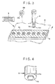
- Figure 3 is a view, in perspective, illustrating a punch and a die array of the perforator;
- Figure 4 is a perspective view illustrating a tip portion of the punch;
- Figure 5 is a view, in section, illustrating important sections of the punch and the die array;
- Figure 6 is a cross-sectional view illustrating a web perforator;
- Figures 7 to 9 are views similar to Fig. 4 but illustrating respective tip portions of other preferred punches;
- Figure 10 is a view illustrating damage around a round punched hole formed by a conventional sheet perforator; and
- Figure 11 is a view illustrating damage around a slot-like punched hole formed by a conventional web perforator.
-
- In Fig. 1 illustrating a sheet perforator of the assembly according to the present invention, the sheet perforator has a
drive mechanism 10 including a motor. Apunch holder 12 is connected via a pair of guidingrods 13 to thedrive mechanism 10, and is drivable to move up and down. On thepunch holder 12 are arranged a number of, e.g. seven,punches 14 extending downward and formed e.g. from high speed steel SKH. A transport mechanism 9 (see Fig. 3) transports a rectangular thinflat metal sheet 15, and inserts it under thepunches 14. Themetal sheet 15 is placed on adie array 16 formed e.g. from special tool steel SKD. When thepunch holder 12 is lowered, thepunches 14 arc inserted into thedie array 16, until thepunches 14 and thedie array 16 cut themetal sheet 15 to form punch holes shaped to be round or elliptical. - In Fig. 2, the
die array 16 has die holes 16a whose inner diameter or width is substantially equal to the width of thepunch 14. Themetal sheet 15 is punched when the die holes 16a receive the advancing punches 14. Thedie array 16 is supported on adie holder 17. After themetal sheet 15 is punched, the waste bits of themetal sheet 15 are discharged through openings 1 7a. Astripper plate 18 is disposed fixedly on thedie array 16. Themetal sheet 15 is inserted between thestripper plate 18 and thedie array 16. When thepunch holder 12 is raised after punching themetal sheet 15, thestripper plate 18 contacts themetal sheet 15, separates the risingpunches 14 from themetal sheet 15, and keeps themetal sheet 15 from rising with thepunches 14. The bottom of thestripper plate 18 has acushioning material 19 for contact with themetal sheet 15. The cushioningmaterial 19 consists of a sheet of polyethylene terephthalate (PET) 170 µm thick. Note that, after thepunches 14 are retracted from themetal sheet 15, thetransport mechanism 9 moves themetal sheet 15 from between thedie array 16 and thepunches 14. - In Fig. 3 illustrating the
metal sheet 15, thepunches 14 and thedie array 16, themetal sheet 15 is constituted of a PS plate 15a and a light-shielding lining sheet 15b attached thereto. A punching blade edge 14a around thepunches 14, the top face of thedie array 16, and the inside of the die holes 16a is coated with non-crystalline hard carbon. Although either thepunches 14 or thedie array 16 may lack such a coating, it is preferred to coat both. The roughness of the carbon coat of those faces is 0.8 µm or less. As illustrated in Figs. 4 and 5, thepunches 14 each have a steppedtip portion 14b shaped as a cylinder smaller in diameter than the main body of the punch, thereby reducing the distortion or unwanted raised margin about the punched hole. The height H of thetip portion 14b is at least half the thickness of themetal sheet 15, and at most twice that thickness. There is a slight clearance between thepunches 14 and the die holes 16a. The clearance C as shown is half of the difference between diameters of thepunch 14 and the die hole 16a, and is in the range of 10 to 30% of the thickness of themetal sheet 15. Note that the perforator may lack thetransport mechanism 9 and instead be fed manually. - Fig. 6 illustrates a preferred web perforator, in which a
continuous web 35 constituted of PS plate and light-shielding lining paper is repeatedly punched in synchronism with the intermittent progressive conveyance of theweb 35 by atransport mechanism 39. Elements similar to those of the sheet perforator in Figs. 1 and 2 are designated with the identical numerals. In the web perforator, astripper plate 38 is slidably mounted on apunch holder 32. When thepunch holder 32 Is lowered, thestripper plate 38 comes into contact with astopper 22. Subsequently, thepunch holder 32 is lowered against the bias of astripper spring 23, until thepunches 14 punch theweb 35. After punching, thepunch holder 32 with thepunches 14 Is raised, and thestripper plate 38 is raised. Note thatreference numeral 33 designates guiding rods, 36 a die array, and 37 a die holder. - An experiment was conducted with the
web 35 In which lining paper was attached to the PS aluminum plate. The lining paper was of polyethylene. The web perforator in Fig. 6 was used, of which the carbon coat had a roughness of 0.8 µm or less, as described above. The clearance C between thepunches 14 and the die holes in thedie array 36 was 10% of the thickness of theweb 35. The experiment resulted in punched holes that were regular and of good shape, even after 5,000 punching operations of the web perforator: and this is a success when compared with a conventional assembly, in which 100 to 500 operations of punching thesame web 35 resulted in generation of an unwanted raisedportion 5 on the periphery ofpunch holes 3, as illustrated in Fig. 11. - Another experiment was conducted. Three
metal sheets 15, each of polyethylene lining paper 15b attached to PS aluminum plates 15a, were superposed, and were loaded together into the sheet perforator in Figs. 1 and 2 as described above. The experiment resulted in punched holes of regularly good shapes, even after 50,000 repetitions of the punching operation of the sheet perforator: and this is again a success as compared with a conventional assembly, in which 60 operations of punching round holes in thesame metal sheet 15 resulted in generation of improperly shaped punched holes, because the punches and die holes had worn until they were dull. - Still another experiment was conducted with the superposed three sheets of
metal sheets 15 inclusive of PS aluminum plates 15a attached to lining sheets 15b produced all from pulp. Each of the PS plates 15a was 150 µm thick. The sheet perforator of Figs. 1 and was used. Thepunches 14 each had acylindrical tip portion 14b. Thepunches 14 and/or the die holes 16a were coated with the carbon above, which had a roughness of 0.8 µm or less. The clearance C defined between thepunches 14 and the die holes 16a was 20% of the thickness of the thin plate. The bottom of thestripper plate 18 had thereon cushioningmaterial 19, which was polyethyleneterephthalate cushioning material punches 14 were 4.0 mm across. Thetip portion 14b was 2.0 mm across and 0.2 mm high. - The experiment resulted in punched holes of good shape with only small raised margins and without damage, even after 5,000 punching operations of the sheet perforator. Very little powder from the tin plate stuck to the punching blade edges. The performance of the sheet perforator when punching the metal sheets with pure pulp lining paper was equal to or better than that when punching the metal sheets with the polyethylene lining paper. This was a success as compared with a conventional assembly, in which 10 to 20 times of operation of punching the same thin plate resulted in generation of unwanted raised borders around punched holes by an amount twice as great as the novel assembly.
- Note that the punches and die array to be used in the present invention can be formed, not only from the high speed steel SKH or the special tool steel SKD above described, but from sufficiently hard other steels, such as various high speed steels and high speed steel powder. It is also possible to construct punches differently: the
punch 25 in Fig. 7 has a conical tip portion 25a; thepunch 26 in Fig. 8 has a truncated conical tip portion 26a; and thepunch 27 in Fig. 9 has a quadrangular stepped tip portion 27a. - Note that, although the punched holes formed in the above embodiments are round, alternatively punched holes shaped like slots having round corners can be formed, by use of punches shaped correspondingly. Although the metal sheets and web constitute PS aluminum plates in the above embodiment, the present invention is applicable to punching PS steel plates.
- Although the present Invention has been fully described by way of the preferred embodiments thereof with reference to the accompanying drawings, various changes and modifications will be apparent to those having skill in this field. Therefore, unless otherwise these changes and modifications depart from the scope of the present invention as defined by the appended claims they should be construed as being included therein.
Claims (18)
- An assembly comprising a metal plate (15, 35) and an apparatus for forming a hole in said metal plate, said apparatus having a moveable punch means (14, 25, 26, 27), die means (16, 36) co-operating with said moveable punch means, and retaining means (18, 38) for retaining said plate adjacent said die means when said punch means separates from said die means after said punch means forms said hole in said plate; characterised in that for forming a hole in a presensitized lithographic metal plate covered by a light-shielding lining paper, said paper being a pure pulp paper or a resin containing paper, said moveable punch means (14, 25, 26, 27) face said lining paper of said metal plate received in said apparatus, at least one of said punch means and die means is coated with non-crystalline hard carbon having a surface roughness of 0.8µm or less, a clearance between said punch means (14, 25, 26, 27) and said die means (16, 36) is from 10 to 30% of the thickness of said plate (15, 35), and an advancing end of said punch means (14, 25, 26, 27) is provided with a tip portion (14b, 25a, 26a, 27a), having a width less than the width of the remainder of said punch means and being smaller than a die hole in said die means.
- An assembly as defined in claim 1, wherein said punch means (14, 25, 26, 27) has at least one punch and said die means (16. 36) has at least one die hole into which said punch is fitted.
- An assembly as defined in claim 1 or 2, wherein said retaining means (18,38) is a single plate having a hole through which said punch (14,25,26,27) extends.
- An assembly as defined in any one of claims 1 to 3, further comprising transport means (9,39) for transporting said plate to said die.
- An assembly as defined in any one of claims 1 to 4, wherein said plate (15,35) is of one piece.
- An assembly as defined in claim 4, wherein said plate (15,35) is continuous, said transport means (9,39) transports said plate intermittently, and said punch (14,25,26,27) is driven upon each step of said intermittent transportation.
- An assembly as defined in any one of claims 1 to 6, further comprising:movable holder means (12,32) on which said punch means (14,25,26,27) and said retaining means (18,38) are mounted; anddrive means (10) for moving said holder means, said retaining means coming into contact with said plate (15,35) while said holder means is moved toward said die (16,36) by said drive means, said holder means subsequently moving further toward said die, and said punch means advancing beyond said retaining means.
- An assembly as defined in claim 7, which further comprises connecting means for connecting said retaining means (18,38) to said holder means (12,32) for allowing said retaining means during contact with said plate (15,35) to shift to a first position wherein said retaining means is relatively close to said holder means, and for transmitting to said retaining means a movement of said holder means away from said die, while said retaining means is shifted to a second position wherein said retaining means is farther from said holder means than in said first position; and
wherein said holder means is so moved as to retract said punch from said plate, and so as to shift said retaining means from said first position to said second position, subsequently said connecting means transmits movement of said holder means to said retaining means so as to retract said retaining means together with said punch. - An assembly as defined in claim 7, further comprising bias means (23) disposed between said retaining means and said holder means for being compressed during contact of said retaining means with said plate and for recovering from said compression upon retraction of said retaining means from said plate, said bias means keeping said retaining means in contact with said plate while said punch is retracted from said plate.
- An assembly as defined in any one of claims 7 to 9, wherein said punch means (14,25,26,27) comprises a plurality of punches.
- An assembly as defined in any one of claims 1 to 10, wherein said retaining means (18,38) is provided with a cushioning material (19) mounted for contact with said plate material (15,35).
- An assembly as defined in claim 11, wherein said cushioning material includes a resinous sheet.
- An assembly as defined in any one of claims 1 to 12, wherein said plate material includes aluminum.
- An assembly as defined in any one of claims 1 to 13, wherein said tip portion (14b,25a,26a,27a) of said punch means is 0.5 to 2.0 times as long as said thickness of said plate material.
- An assembly as defined in any one of claims 1 to 14, wherein said tip portion is conical.
- An assembly as defined in any one of claims 1 to 14, wherein said tip portion is shaped like a truncated cone.
- An assembly as defined in any one of claims 1 to 14, wherein said tip portion is cylindrical.
- An assembly as defined in any one of claims 1 to 14, wherein said tip portion is shaped prismatic.
Applications Claiming Priority (3)
| Application Number | Priority Date | Filing Date | Title |
|---|---|---|---|
| JP326983/92 | 1992-12-07 | ||
| JP32698392 | 1992-12-07 | ||
| JP32698392 | 1992-12-07 |
Publications (2)
| Publication Number | Publication Date |
|---|---|
| EP0609520A1 EP0609520A1 (en) | 1994-08-10 |
| EP0609520B1 true EP0609520B1 (en) | 2001-05-23 |
Family
ID=18193994
Family Applications (1)
| Application Number | Title | Priority Date | Filing Date |
|---|---|---|---|
| EP93119680A Expired - Lifetime EP0609520B1 (en) | 1992-12-07 | 1993-12-07 | Perforator for metal plate |
Country Status (3)
| Country | Link |
|---|---|
| US (1) | US5992280A (en) |
| EP (1) | EP0609520B1 (en) |
| DE (1) | DE69330244T2 (en) |
Families Citing this family (26)
| Publication number | Priority date | Publication date | Assignee | Title |
|---|---|---|---|---|
| JP3676192B2 (en) * | 2000-05-26 | 2005-07-27 | 本田技研工業株式会社 | Punching method for continuously variable transmission belt elements |
| DE20013526U1 (en) * | 2000-08-05 | 2000-12-07 | Avdel Verbindungselemente | Device for connecting sheets by punch riveting or clinching |
| JP3629698B2 (en) * | 2000-10-03 | 2005-03-16 | 株式会社デンソー | Fluid injection nozzle injection hole processing apparatus and fluid injection nozzle injection hole processing method |
| US8087333B2 (en) * | 2002-12-17 | 2012-01-03 | Ones Co., Ltd. | Method for press punching a hole in sheet metal and press die |
| AT502173B1 (en) * | 2004-03-12 | 2007-02-15 | Gassner Ges M B H & Co Kg | Process to perforate sheet metal panel by initial presentation of cutter to one side followed by action of press in reverse direction |
| DE102004016819B3 (en) * | 2004-04-05 | 2005-08-18 | Hilti Ag | Cutting segment for drill heads, circular saw blades and separating plates comprises cutting surface forming surface sections in stepped manner |
| JP4769799B2 (en) * | 2004-06-25 | 2011-09-07 | メルツ,カール | Manufacturing method of bimetal saw blade, band saw or circular circular saw blade |
| US20060236536A1 (en) * | 2005-03-28 | 2006-10-26 | Seiko Epson Corporation | Die apparatus, method for producing perforated work plate, perforated work plate, liquid-jet head and liquid-jet apparatus |
| US7308814B2 (en) * | 2005-10-13 | 2007-12-18 | Gassner Ges.M.B.H. & Co Kg | Method for perforating a sheet |
| ATE427173T1 (en) * | 2005-10-14 | 2009-04-15 | Gassner Ges M B H & Co Kg | METHOD AND DEVICE FOR PUNCHING A SHEET METAL |
| KR101295337B1 (en) * | 2009-01-22 | 2013-08-12 | 오일레스고교 가부시키가이샤 | Sheet metal punching apparatus and method thereof |
| JP2012000727A (en) * | 2010-06-17 | 2012-01-05 | Nissan Motor Co Ltd | Workpiece cutting apparatus and method for cleaning cutting blade of workpiece cutting apparatus |
| KR101007635B1 (en) * | 2010-06-18 | 2011-01-12 | 김민정 | Multi-array progressive drawing machine without circular lance |
| CN102397934A (en) * | 2010-09-15 | 2012-04-04 | 上虞市风帆电气附件有限公司 | Tie body punching device for stainless steel tie |
| EP2532452B1 (en) * | 2011-06-10 | 2014-03-12 | TRUMPF Werkzeugmaschinen GmbH + Co. KG | Method for punching and straightening sheet metal |
| CN103143903A (en) * | 2011-12-07 | 2013-06-12 | 富泰华工业(深圳)有限公司 | Method for processing hole of metal piece |
| DE102012013771B4 (en) | 2012-07-11 | 2022-10-20 | Fraunhofer-Gesellschaft zur Förderung der angewandten Forschung e.V. | Cutting tool and cutting device equipped with such |
| CN104438583A (en) * | 2014-12-08 | 2015-03-25 | 无锡朗贤汽车组件研发中心有限公司 | Die capable of reducing abrasion of punch head of thermoformed steel plate |
| CN104438585A (en) * | 2014-12-08 | 2015-03-25 | 无锡朗贤汽车组件研发中心有限公司 | Die for reducing abrasion of hot-forming steel plate piercing punch |
| BR112017011498A2 (en) * | 2014-12-10 | 2018-04-10 | Nippon Steel & Sumitomo Metal Corporation | crude block, shaped article, die assembly and crude block production method |
| JP5958565B2 (en) * | 2015-01-14 | 2016-08-02 | Jfeスチール株式会社 | Punching method, punching apparatus, and method for manufacturing laminated iron core |
| CN105195611B (en) * | 2015-09-21 | 2017-10-31 | 宁波鑫淼机械有限公司 | A kind of multi-station Die Used in Pressworking of automobile moulding part |
| DE102016102656B4 (en) | 2016-02-16 | 2024-03-28 | Schuler Pressen Gmbh | Device and method for processing metal raw parts and for sorting metal waste parts |
| US10987745B2 (en) * | 2019-01-25 | 2021-04-27 | Snap-On Incorporated | Method of manufacturing socket punches |
| KR102474961B1 (en) * | 2020-03-18 | 2022-12-06 | 엘지전자 주식회사 | Refrigerator and manufacturing apparatus of out plate for refrigerator |
| CN111922190B (en) * | 2020-07-30 | 2021-07-06 | 东风商用车有限公司 | Stamping die and prestress punching process thereof |
Family Cites Families (34)
| Publication number | Priority date | Publication date | Assignee | Title |
|---|---|---|---|---|
| US389404A (en) * | 1888-09-11 | Ohaeles p | ||
| US3125917A (en) * | 1964-03-24 | Punch and die assembly having spaced tool positioning plates | ||
| US770239A (en) * | 1903-09-23 | 1904-09-13 | Thomas H Lovejoy | Punch. |
| US927311A (en) * | 1908-01-06 | 1909-07-06 | Worcester Pressed Steel Company | Method of making ball-cups. |
| US1166613A (en) * | 1915-07-06 | 1916-01-04 | William J Mackle | Punch. |
| US2017195A (en) * | 1933-02-02 | 1935-10-15 | American Perforator Company | Perforating machine |
| US2372011A (en) * | 1941-10-16 | 1945-03-20 | Peerless Tube Company | Method of making lead articles |
| US2369896A (en) * | 1943-07-16 | 1945-02-20 | Chain Belt Co | Punching metal bars, plates, and the like |
| US2763325A (en) * | 1953-06-08 | 1956-09-18 | Western Electric Co | Stripper assembly for punch presses |
| US3189238A (en) * | 1961-02-20 | 1965-06-15 | Lemert Engineering Co Inc | Method of working hard brittle metals |
| US3143026A (en) * | 1962-10-01 | 1964-08-04 | Wood Conversion Co | Tool for punching acoustic holes |
| GB1122286A (en) * | 1964-11-02 | 1968-08-07 | Minnie Punch And Die Company I | Punching apparatus |
| US3350972A (en) * | 1964-12-18 | 1967-11-07 | Du Pont | Low friction punch tool |
| GB1282282A (en) * | 1968-09-27 | 1972-07-19 | British Aero Component Ltd | Improvements in die sets |
| US3642522A (en) * | 1969-07-15 | 1972-02-15 | Suisse Horlogerie Rech Lab | Method for producing hard coatings on a surface |
| BE758810A (en) * | 1969-11-15 | 1971-04-16 | Kondo Kazuyoshi | PRECISION SHEAR PROCESS |
| US3777601A (en) * | 1971-03-29 | 1973-12-11 | P Strandell | Punching apparatus |
| US3889563A (en) * | 1973-12-26 | 1975-06-17 | William S Westermann | Apparatus for trimming and removing the flashing from phonograph records |
| JPS5118259A (en) * | 1974-08-06 | 1976-02-13 | Tomio Ishida | Netsukanfuoomaaniokeru naigairindojiseizosochi |
| US4143569A (en) * | 1976-02-23 | 1979-03-13 | Joseph Marconi | Die holder for punch presses |
| JPS53137835A (en) * | 1977-05-09 | 1978-12-01 | Toyoda Chuo Kenkyusho Kk | Method of forming carbide layer of va group element or chrome on surface of iron alloy material |
| JPS551941A (en) * | 1978-06-22 | 1980-01-09 | Toshiba Corp | Preventing method for slug rising of thin plate steel plates |
| FR2520272A1 (en) * | 1982-01-25 | 1983-07-29 | Westinghouse Electric Corp | CEMENTITIOUS CARBIDE CUTTING TOOL AND METHOD FOR MANUFACTURING AND USING SUCH A TOOL |
| US4526077A (en) * | 1983-07-21 | 1985-07-02 | Detroit Punch & Retainer Corporation | Heavy duty punch |
| JPH0716918B2 (en) * | 1985-04-17 | 1995-03-01 | 富士写真フイルム株式会社 | Continuous punching / cutting device |
| JPS63203223A (en) * | 1987-02-18 | 1988-08-23 | Toshiba Corp | Press punch subjected to coating by ceramics |
| JPH01210299A (en) * | 1988-02-17 | 1989-08-23 | Fuji Photo Film Co Ltd | Web punching device |
| JPH0353070A (en) * | 1989-07-20 | 1991-03-07 | Mitsubishi Materials Corp | Surface coated tool member having excellent wear resistance |
| US5235881A (en) * | 1991-04-26 | 1993-08-17 | Toyota Jidosha Kabushiki Kaisha | Piercing die whose punch has different amounts of chamfer at different outer peripheral edge portions |
| DE9116425U1 (en) * | 1991-07-19 | 1992-10-08 | Karl Marbach Gmbh & Co, 7100 Heilbronn, De | |
| US5410927A (en) * | 1993-07-16 | 1995-05-02 | Amada Compmany, Limited | Low noise punch tool |
| US5412972A (en) * | 1993-11-03 | 1995-05-09 | Crenshaw Die And Manufacturing Corporation | Method of making a gasket |
| US5492001A (en) * | 1994-01-18 | 1996-02-20 | Kabushiki Kaisha Yutaka Giken | Method and apparatus for working burred portion of workpiece |
| JP2935817B2 (en) * | 1994-09-29 | 1999-08-16 | 日東工器株式会社 | Hole forming method for forming a tapered through hole in a workpiece by pressing and tool for forming the hole |
-
1993
- 1993-12-07 DE DE69330244T patent/DE69330244T2/en not_active Expired - Fee Related
- 1993-12-07 EP EP93119680A patent/EP0609520B1/en not_active Expired - Lifetime
-
1997
- 1997-04-25 US US08/847,812 patent/US5992280A/en not_active Expired - Fee Related
Also Published As
| Publication number | Publication date |
|---|---|
| US5992280A (en) | 1999-11-30 |
| DE69330244D1 (en) | 2001-06-28 |
| DE69330244T2 (en) | 2001-09-06 |
| EP0609520A1 (en) | 1994-08-10 |
Similar Documents
| Publication | Publication Date | Title |
|---|---|---|
| EP0609520B1 (en) | Perforator for metal plate | |
| US7284462B2 (en) | Flexible die and method for its manufacture | |
| US4625612A (en) | Rotary portapunch assembly | |
| CA1194778A (en) | Rotary cutting die with scrap ejection | |
| US4224851A (en) | Knockout for punch scrap | |
| US3835746A (en) | Die assembly and rule mounting means therefor | |
| US3786732A (en) | Cutting and scoring die | |
| EP1401620B1 (en) | Die cutting apparatus and method | |
| US4509396A (en) | Apparatus for making holes in thick stacks of paper | |
| GB2024081A (en) | Scrap removal means for rotary punching machines | |
| WO1983000112A1 (en) | A punching apparatus, particularly for punching labels and similar printed matter items | |
| US4435885A (en) | Process and apparatus for manufacturing storage battery plates | |
| JP3612123B2 (en) | Running hole drilling device | |
| EP1066904B1 (en) | Planographic printing plate cutting device and method | |
| JP3372315B2 (en) | Perforator | |
| JP2003025287A (en) | Punching blade structure and punching die | |
| JP2000051966A (en) | Die button | |
| JP3401908B2 (en) | Punching punching die and punching cutting method | |
| JP4512307B2 (en) | Stripping device female mold and stripping device | |
| JP2001088092A (en) | Method and device for removing punched-out waste produced in punching out paper material | |
| SU1593741A1 (en) | Method of wasteless progressive forming and die for effecting same | |
| JP3058732U (en) | Dust punching device for molded sheet | |
| GB2320906A (en) | Ultrasonic cutting machine | |
| JP2987082B2 (en) | Ejection device for punching waste in paper cutting machine | |
| JP2000084896A (en) | Punched piece removal device |
Legal Events
| Date | Code | Title | Description |
|---|---|---|---|
| PUAI | Public reference made under article 153(3) epc to a published international application that has entered the european phase |
Free format text: ORIGINAL CODE: 0009012 |
|
| AK | Designated contracting states |
Kind code of ref document: A1 Designated state(s): DE NL |
|
| 17P | Request for examination filed |
Effective date: 19950111 |
|
| RBV | Designated contracting states (corrected) |
Designated state(s): DE NL |
|
| 17Q | First examination report despatched |
Effective date: 19970407 |
|
| GRAG | Despatch of communication of intention to grant |
Free format text: ORIGINAL CODE: EPIDOS AGRA |
|
| GRAG | Despatch of communication of intention to grant |
Free format text: ORIGINAL CODE: EPIDOS AGRA |
|
| GRAH | Despatch of communication of intention to grant a patent |
Free format text: ORIGINAL CODE: EPIDOS IGRA |
|
| GRAH | Despatch of communication of intention to grant a patent |
Free format text: ORIGINAL CODE: EPIDOS IGRA |
|
| GRAA | (expected) grant |
Free format text: ORIGINAL CODE: 0009210 |
|
| AK | Designated contracting states |
Kind code of ref document: B1 Designated state(s): DE NL |
|
| REF | Corresponds to: |
Ref document number: 69330244 Country of ref document: DE Date of ref document: 20010628 |
|
| PLBE | No opposition filed within time limit |
Free format text: ORIGINAL CODE: 0009261 |
|
| STAA | Information on the status of an ep patent application or granted ep patent |
Free format text: STATUS: NO OPPOSITION FILED WITHIN TIME LIMIT |
|
| 26N | No opposition filed | ||
| PG25 | Lapsed in a contracting state [announced via postgrant information from national office to epo] |
Ref country code: NL Free format text: LAPSE BECAUSE OF NON-PAYMENT OF DUE FEES Effective date: 20020701 |
|
| NLV4 | Nl: lapsed or anulled due to non-payment of the annual fee |
Effective date: 20020701 |
|
| PGFP | Annual fee paid to national office [announced via postgrant information from national office to epo] |
Ref country code: DE Payment date: 20080130 Year of fee payment: 15 |
|
| PG25 | Lapsed in a contracting state [announced via postgrant information from national office to epo] |
Ref country code: DE Free format text: LAPSE BECAUSE OF NON-PAYMENT OF DUE FEES Effective date: 20090701 |