EP0609239B1 - Dispositif de biopsie lateral - Google Patents
Dispositif de biopsie lateral Download PDFInfo
- Publication number
- EP0609239B1 EP0609239B1 EP92919724A EP92919724A EP0609239B1 EP 0609239 B1 EP0609239 B1 EP 0609239B1 EP 92919724 A EP92919724 A EP 92919724A EP 92919724 A EP92919724 A EP 92919724A EP 0609239 B1 EP0609239 B1 EP 0609239B1
- Authority
- EP
- European Patent Office
- Prior art keywords
- catheter
- anvil
- biopsy device
- lumen
- distal end
- Prior art date
- Legal status (The legal status is an assumption and is not a legal conclusion. Google has not performed a legal analysis and makes no representation as to the accuracy of the status listed.)
- Expired - Lifetime
Links
- 238000001574 biopsy Methods 0.000 title claims abstract description 61
- 239000012530 fluid Substances 0.000 claims description 10
- 238000003780 insertion Methods 0.000 claims description 7
- 230000037431 insertion Effects 0.000 claims description 7
- 239000000463 material Substances 0.000 claims description 6
- 238000000034 method Methods 0.000 description 9
- 208000031481 Pathologic Constriction Diseases 0.000 description 3
- 208000037804 stenosis Diseases 0.000 description 3
- 230000036262 stenosis Effects 0.000 description 3
- 239000000853 adhesive Substances 0.000 description 2
- 230000001070 adhesive effect Effects 0.000 description 2
- 230000000721 bacterilogical effect Effects 0.000 description 2
- 230000010339 dilation Effects 0.000 description 2
- 239000012634 fragment Substances 0.000 description 2
- 238000012986 modification Methods 0.000 description 2
- 230000004048 modification Effects 0.000 description 2
- 238000005070 sampling Methods 0.000 description 2
- 238000000926 separation method Methods 0.000 description 2
- 206010016717 Fistula Diseases 0.000 description 1
- 206010033557 Palpitations Diseases 0.000 description 1
- 229910001260 Pt alloy Inorganic materials 0.000 description 1
- 230000004075 alteration Effects 0.000 description 1
- 210000004204 blood vessel Anatomy 0.000 description 1
- 239000004020 conductor Substances 0.000 description 1
- 238000011109 contamination Methods 0.000 description 1
- 239000003814 drug Substances 0.000 description 1
- 230000009977 dual effect Effects 0.000 description 1
- 210000003238 esophagus Anatomy 0.000 description 1
- 230000003890 fistula Effects 0.000 description 1
- 210000001035 gastrointestinal tract Anatomy 0.000 description 1
- 238000007429 general method Methods 0.000 description 1
- 210000004072 lung Anatomy 0.000 description 1
- 230000013011 mating Effects 0.000 description 1
- 229910052751 metal Inorganic materials 0.000 description 1
- 239000002184 metal Substances 0.000 description 1
- 230000001737 promoting effect Effects 0.000 description 1
- 230000003252 repetitive effect Effects 0.000 description 1
- 238000007790 scraping Methods 0.000 description 1
- 210000000813 small intestine Anatomy 0.000 description 1
- 239000010935 stainless steel Substances 0.000 description 1
- 229910001220 stainless steel Inorganic materials 0.000 description 1
- 239000000126 substance Substances 0.000 description 1
- 230000008467 tissue growth Effects 0.000 description 1
- 210000001635 urinary tract Anatomy 0.000 description 1
Images
Classifications
-
- A—HUMAN NECESSITIES
- A61—MEDICAL OR VETERINARY SCIENCE; HYGIENE
- A61B—DIAGNOSIS; SURGERY; IDENTIFICATION
- A61B10/00—Other methods or instruments for diagnosis, e.g. instruments for taking a cell sample, for biopsy, for vaccination diagnosis; Sex determination; Ovulation-period determination; Throat striking implements
- A61B10/02—Instruments for taking cell samples or for biopsy
- A61B10/04—Endoscopic instruments
-
- A—HUMAN NECESSITIES
- A61—MEDICAL OR VETERINARY SCIENCE; HYGIENE
- A61B—DIAGNOSIS; SURGERY; IDENTIFICATION
- A61B10/00—Other methods or instruments for diagnosis, e.g. instruments for taking a cell sample, for biopsy, for vaccination diagnosis; Sex determination; Ovulation-period determination; Throat striking implements
- A61B10/02—Instruments for taking cell samples or for biopsy
- A61B2010/0225—Instruments for taking cell samples or for biopsy for taking multiple samples
Definitions
- This invention relates generally to a device for performing biopsies or for removing fragments of tissue to relieve an obstruction in areas of stenosis.
- the invention relates to biopsy sampling or removing tissue in any remote luminal structure or cavity within a patient.
- tissue samples for microscopic, chemical or bacteriologic analysis from deep within luminal structures that can only be approached by catheterization methods using endoscopic or fluoroscopic control, or on occasion blindly by palpitation.
- General methods and devices currently in use for biopsy include needles with hooks that allow the tearing of the tissue samples, sharpened needles that allow the cutting of fragments, and punch or grasping forceps that either cut or tear the samples. These devices all require pushing or pulling the device against the tissue to be sampled. Also, it is often difficult to position these biopsy devices adjacent to the area that must be sampled. The stiffness and shape of these devices make them difficult and often impossible to position or guide through a long and tortuous lumen in a patient, and particularly to bend the device around curves in the lumen.
- a biopsy device that is structurally simple but which obtains a tissue sample without pulling on the tissue to be sampled, and which includes a thin flexible body which enables the device to travel through nonlinear passageways within a patient to reach otherwise inaccessible locations.
- a biopsy device comprising a catheter having a proximal end and an opposite other distal end, said catheter having a lumen extending from said proximal end to said distal end.
- a flexible shaft in the form of an elongate rod or conductor is slidably disposed within the lumen.
- a plug is positioned within the lumen at the distal end of the catheter and the elongate rod and is guided through a longitudinal bore in the plug.
- the biopsy device includes an anvil and a cutting edge which co-operates with the anvil.
- One object of the present invention is to provide an improved biopsy device for sampling and/or removal of tissue in any luminal structure or cavity within a patient.
- Another object of the present invention is to provide a device which allows repetitive biopsies or scraping of tissue samples without the need to remove the device between samples.
- Still another object of the present invention is to provides a less invasive method for obtaining tissue samples from remote locations within a patient.
- a biopsy device comprising a flexible catheter having proximal end and an opposite other distal end, said catheter having lumen extending from said proximal end to said distal end;
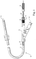
- FIG. 1 shows a lateral biopsy device 10 according to one aspect of the present invention.
- the device includes an elongated flexible catheter 11 and an elongated flexible shaft 12 disposed within a central lumen 19 of catheter 11.
- Catheter 11 could range from a few to several hundred centimeters in length, depending upon the particular application.
- Attached to the proximal end of shaft 12 is gripping means 13.
- Gripping means 13 is shown as a releasable clamp but could equally well be any structure which permits the physician to advance and retract shaft 12 with respect to catheter 11.
- Attached to the distal end of shaft 12 is anvil 14.
- Anvil 14 may be attached by any suitable means such as by threaded engagement with shaft 12, adhesive, or by a welded connection.
- the diameter of shaft 12 is significantly smaller than central lumen 19 of catheter 11 in order that fluid may pass freely along the length of the central lumen of catheter 11.
- the proximal end of catheter 11 is connected to a standard Tuohy-Borst adapter 15 which is well known in the art and includes an injection-aspiration port 18.
- Nut 16 is attached to the proximal end of adapter 15 and compresses washer 17 in place to keep exit port 9 fluid-tight. In this way, any fluid injected, or suction applied, at port 18 acts through central lumen 19 and out the distal end of catheter 11.
- catheter 11 When gripping means 13 is advanced toward nut 16, against the action of spring 20, the flexible shaft 12 advances within central lumen 19 and results in separating anvil 14 from the distal end of catheter 11. When gripping means 13 is released, spring 20 acts to automatically retract flexible shaft 12 back to its original position with anvil 14 once again in contact with the distal end of catheter 11. Biasing spring 20 is a desirable but not essential element to the proper functioning of the invention; without bias spring 20, the operator would simply have to manually retract anvil 14 by pulling backward on gripping means 13.
- catheter 11 could be as small as one millimeter in diameter, but a typical size for the catheter is a 7 French catheter.
- Catheter 11 could be formed from any suitable flexible medical grade tubing material. Also, depending upon the application, catheter 11 could also be made to have variable stiffness along its length.
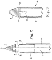
- FIG. 2 depicts the distal end of the biopsy device shown in FIG. 1 after gripping means 13 has advanced shaft 12 with respect to catheter 11, thus separating anvil 14 from the distal end of catheter 11.
- Anvil 14 includes a smoothly rounded tip 25 which aids in the atraumatic insertion of the biopsy device, and an annular lower surface 24 which is remote from the rounded tip.
- metal tube portion 22 which is attached to the distal end of catheter 11 at circumfrential location 21 by a suitable attachment means such as mating threads or adhesives.
- Tubular portion 22 includes an annular cutting edge 23 which extends beyond the distal end of catheter 11 and contacts annular surface 24 of anvil 14 when the anvil is retracted against the tubular portion 22.
- anvil 14 includes a cavity 26 which can serve to hold a portion of the tissue sample which is removed from the patient. Again, depending upon the particular application and the desired sample size, cavity 26 could be sized to a variety of volumes, or be eliminated altogether.
- Anvil 14 is preferably formed of medical grade stainless steel but could alternatively be formed of a radiopaque material, such as a platinum alloy, which would enable the physician to track the position of the device via x-rays during the catheter insertion procedure. It may also be desirable to inject radiopaque fluids out the distal end of the biopsy device to further aid the physician during the insertion procedure. This could be accomplished by injecting radiopaque fluids through port 18 of Fig. 1 while slightly separating the anvil from the distal tip of the catheter to permit the radiopaque fluid to escape into the patient.
- FIG. 3 shows another embodiment of a biopsy device 30 according to another aspect of the present invention. While only the distal end of device 30 is shown, the remainder of the device is identical in configuration to the biopsy device 10 shown in FIG. 1.
- Biopsy device 30 includes a flexible elongated catheter 31, and a flexible elongated shaft 32 running through the central lumen of catheter 31. Attached to the distal end of shaft 32 is anvil 35.
- This device is different from the device shown in FIG. 2 in that the annular cutting edge 34 is included on the lower portion of anvil 35, and is received against the annular surface 33 on the distal tip of catheter 31.
- the annular cutting edge 23 is part of the distal tip of the catheter as opposed to part of the anvil 14.
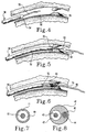
- FIGS. 4-6 depict another embodiment of the present invention during the biopsy procedure within a patient.
- biopsy device 50 includes a filiform wire guide tip 55 extending distally from the anvil 54 in order to aid the physician during the catheter insertion procedure, but which is otherwise identical to the device of Fig. 1.
- Guide tip 55 typically ranges in length from one to fifteen centimeters in length, but could be outside this range depending upon the particular application.
- Guide tip 55 could also include a radiopaque element to aid the physician during the insertion procedure.
- FIG. 4 shows the biopsy device 50 being advanced through a portion of a non-linear passageway 58 within a patient toward a tissue growth 59 which is desired to be sampled.
- FIG. 1 shows the biopsy device 50 being advanced through a portion of a non-linear passageway 58 within a patient toward a tissue growth 59 which is desired to be sampled.
- FIG. 5 shows the biopsy device 50 after it has arrived at the desired location and after the anvil 54 has been separated from the distal tip 53 of catheter 51 in order to draw in a portion of the tissue 59 to be sampled.
- the cutting means of the device are thereby exposed to the tissue when anvil 54 is separated from the distal end of the catheter.
- suction can be applied though the central lumen of the catheter 51 via an aspiration port located at the proximal end of the catheter, such as port 18 shown in FIG. 1.
- the size of the biopsy sample is determined by a number of independently controllable factors including the separation distance of the anvil from the catheter before cutting, the diameter of the central lumen of the catheter, the diameter of the shaft, the size of any cavity that may exist on the underside of the anvil, and the vacuum or suction level utilized during the cutting procedure. It may also be desirable to include calibration marks, such as the marks 8 shown in Fig. 1, on the proximal end of the biopsy device so that the physician can precisely determine and control the separation distance between the anvil and the catheter during the cutting procedure.
- FIG. 6 shows biopsy device 50 after a tissue sample 60 has been removed.
- Tissue sample 60 is removed by retracting shaft 52 thereby positioning anvil 54 against the distal tip 53 of catheter 51.
- the tissue sample 60 is cut when the annular surface of anvil 54 is forced into contact with the annular cutting edge 53 of the distal tip of catheter 51.
- the biopsy device 50 is withdrawn from the patient.
- the steps shown in FIGS. 5 and 6 are repeated as necessary before withdrawing the biopsy device from the patient.
- FIG. 7 shows a cross-section of the biopsy device 10 shown in FIG. 1 looking in the direction of the arrows labeled A.
- central lumen 19 of catheter 11 is significantly larger than the diameter of shaft 12 thereby allowing fluids to pass freely through central lumen 19 adjacent to shaft 12.
- FIG. 8 shows a cross-section of still another embodiment of the present invention in which a dual lumen catheter 41 is used in place of the single lumen catheter shown in the earlier figures.
- first lumen 43 includes a flexible shaft 42 which is functionally analogous to the shaft 12 shown earlier.
- a second lumen 44 which receives a wire guide 45.
- the biopsy device is used by first positioning the wire guide 45 within the patient adjacent to the area to be sampled.
- the biopsy device is threaded over the wire guide by threading lumen 44 over wire guide 45, and then advancing the biopsy device over the wire guide 45 until the distal end of the biopsy device is adjacent the tissue to be sampled.
- Wire guide 45 may be withdrawn after the biopsy device is in place, or wire guide 45 may be left in place after the biopsy device has been used and subsequently withdrawn from the patient. In this way, the physician could obtain a biopsy prior to placing a stent or performing a balloon dilation. Also, the biopsy device could be used after a balloon dilation in order to remove any remaining stenosis from the dilated lumen.
- Biopsy devices according to the above invention could be made for repeated use or could be made disposable for single use only. Also, because the anvil normally is closed against the distal end of the catheter while the device is being withdrawn from the patient, the bacteriologic sample could be retrieved and submitted for culture analysis without risking contamination of the sample by unnecessary contact with other tissues within the patient, or other contaminated matter. Another feature which could be added to the invention would be to supply electric current to the cutting means so that the surrounding tissue is cauterized after a tissue sample has been removed.
- the invention can be used in a myriad of locations within a patient including blood vessels, the urinary tract, the gastrointestinal tract, the esophagus or small intestine, the lungs, or any other non-linear passageway such as a fistula or a cavity.
- the invention is also equally applicable to veterinary medicine. It being understood that only the preferred embodiments have been shown and described and that all changes and modifications that come within the scope of the invention are desired to be protected.
Landscapes
- Health & Medical Sciences (AREA)
- Surgery (AREA)
- Life Sciences & Earth Sciences (AREA)
- Molecular Biology (AREA)
- General Health & Medical Sciences (AREA)
- Radiology & Medical Imaging (AREA)
- Engineering & Computer Science (AREA)
- Biomedical Technology (AREA)
- Heart & Thoracic Surgery (AREA)
- Medical Informatics (AREA)
- Nuclear Medicine, Radiotherapy & Molecular Imaging (AREA)
- Animal Behavior & Ethology (AREA)
- Pathology (AREA)
- Public Health (AREA)
- Veterinary Medicine (AREA)
- Endoscopes (AREA)
- Eye Examination Apparatus (AREA)
- Mechanical Treatment Of Semiconductor (AREA)
- Earth Drilling (AREA)
- Surgical Instruments (AREA)
Claims (16)
- Dispositif de biopsie (10),
comprenant :un cathéter flexible (11) comportant une extrémité proximale et une autre extrémité distale opposée, ce cathéter (11) comportant une lumière (19) allant de l'extrémité proximale à l'extrémité distale ;une tige flexible (12) comportant une extrémité proximale et une autre extrémité distale opposée, cette tige flexible (12) étant montée en glissement à l'intérieur de la lumière (19) et cette lumière (19) ayant un diamètre nettement plus grand que celui de la tige (12) allant de l'extrémité proximale à l'extrémité distale, de manière à faire passer un fluide à travers la lumière (19) et au voisinage de la tige (12),aucun moyen de guidage n'étant prévu pour la tige flexible dans lumière à l'extrémité distale du cathéter ;une enclume (14, 35, 54) reliée à l'extrémité distale de la tige flexible (12), cette enclume (14, 35, 54) étant reliée à l'extrémité distale de la tige flexible (12) et comportant un bout doucement arrondi (25) partant distalement de l'extrémité distale du cathéter (11) pour concourir à l'introduction sans traumatisme du dispositif de biopsie ; etdes moyens de coupe (23, 24, 33, 34) munis d'un bord de coupe annulaire (23, 24) qui définit une zone de diamètre analogue au diamètre de la lumière (19) pour couper le tissu au voisinage de l'extrémité distale du cathéter, ces moyens de coupe (23, 24, 33, 34) étant disposés pour couper le tissu lorsque la tige (12) est déplacée axialement par rapport au cathéter (11) en direction de l'extrémité proximale de ce cathéter. - Dispositif de biopsie selon la revendication 1,
dans lequel
les moyens de coupe comprennent un bord de coupe (23, 34) relié à l'un du cathéter (11) ou de l'enclume (14, 35, 54), et comprennent en outre une surface de coupe (24, 34) reliée à l'autre du cathéter (11) ou de l'enclume (14, 35), de façon que lorsqu'on coupe le tissu, le bord de coupe (23) et la surface de coupe (24, 34) viennent essentiellement en butée. - Dispositif de biopsie selon la revendication 2,
dans lequel
le bord de coupe (23, 34) est annulaire. - Dispositif de biopsie selon la revendication 3,
dans lequel
le cathéter (11) comprend un raccord latéral (18) au voisinage de l'extrémité proximale du cathéter (11), ce raccord latéral (18) étant en communication de fluide avec la lumière (19). - Dispositif de biopsie selon la revendication 4,
dans lequel
la tige (12) est poussée par un ressort (20) pour maintenir le bord de coupe (23, 34) en contact avec la surface de coupe (24). - Dispositif de biopsie selon la revendication 5,
dans lequel
l'enclume (35) comprend une seconde surface (34) opposée au bout doucement arrondi (25) et normalement disposée à proximité de l'extrémité distale du cathéter (11), et la surface de coupe est formée sur cette extrémité distale du cathéter (11), le bord de coupe (34) étant formé sur la seconde surface de l'enclume (35). - Dispositif de biopsie selon la revendication 6,
dans lequel
l'enclume (54) comprend une amorce guide-fil (55) attachée à celle-ci et partant distalement de celle-ci. - Dispositif de biopsie selon la revendication 7,
dans lequel
l'enclume (34) est formée dans un matériau opaque au rayonnement. - Dispositif de biopsie selon la revendication 6,
dans lequel
le cathéter (41) comprend en outre une seconde lumière (44) adjacente à la première lumière (43) et destinée à recevoir un guide-fil (45) à travers celle-ci. - Dispositif de biopsie selon la revendication 2,
dans lequel
l'enclume (14) comprend une seconde surface (24) opposée au bout doucement arrondi (25) de l'enclume (14), et les moyens de coupe ont leur bord de coupe annulaire (23) relié à l'extrémité distale du cathéter (11) et une surface de coupe (24) reliée à la seconde surface de l'enclume (14), le bord de coupe annulaire (23) et la surface de coupe (24) étant normalement en butée. - Dispositif de biopsie selon la revendication 10,
dans lequel
le cathéter (11) comprend un raccord latéral (18) au voisinage de l'extrémité proximale de ce cathéter (11), ce raccord latéral (18) étant en communication de fluide avec la lumière (19). - Dispositif de biopsie selon la revendication 11,
dans lequel
la tige est poussée par un ressort (20) pour maintenir la surface de coupe (24) de l'enclume (14) en contact avec le bord de coupe (23) du cathéter (11). - Dispositif de biopsie selon la revendication 12,
dans lequel
l'enclume (14) comprend une amorce guide-fil (55) attachée à celle-ci et partant distalement de celle-ci. - Dispositif de biopsie selon la revendication 13,
dans lequel
l'enclume est formée dans un matériau opaque au rayonnement. - Dispositif de biopsie selon la revendication 12,
dans lequel
le cathéter (41) comprend en outre une seconde lumière (44) adjacente à la première lumière et destinée à recevoir un guide-fil (45) à travers celle-ci. - Dispositif de biopsie selon la revendication 6 ou 10,
dans lequelle cathéter (41) comprend en outre une seconde lumière (44) adjacente à la première lumière, pour recevoir un guide-fil (45) à travers celle-ci,l'enclume (54) comprend un bout de guide-fil (55) relié à celle-ci et partant distalement de celle-ci,le bout de guide-fil (55) est formé d'un matériau opaque au rayonnement, etl'enclume (54) est formée d'un matériau opaque au rayonnement,le cathéter comprenant en outre une seconde lumière (44) adjacente à la première lumière (43), pour recevoir un guide-fil (45) à travers celle-ci.
Applications Claiming Priority (3)
| Application Number | Priority Date | Filing Date | Title |
|---|---|---|---|
| US75475091A | 1991-09-04 | 1991-09-04 | |
| US754750 | 1991-09-04 | ||
| PCT/US1992/007419 WO1993004630A1 (fr) | 1991-09-04 | 1992-08-31 | Dispositif de biopsie lateral |
Publications (3)
| Publication Number | Publication Date |
|---|---|
| EP0609239A1 EP0609239A1 (fr) | 1994-08-10 |
| EP0609239A4 EP0609239A4 (fr) | 1994-12-07 |
| EP0609239B1 true EP0609239B1 (fr) | 2000-03-22 |
Family
ID=25036162
Family Applications (1)
| Application Number | Title | Priority Date | Filing Date |
|---|---|---|---|
| EP92919724A Expired - Lifetime EP0609239B1 (fr) | 1991-09-04 | 1992-08-31 | Dispositif de biopsie lateral |
Country Status (7)
| Country | Link |
|---|---|
| US (1) | US5685320A (fr) |
| EP (1) | EP0609239B1 (fr) |
| AT (1) | ATE190821T1 (fr) |
| AU (1) | AU2587592A (fr) |
| DE (1) | DE69230829T2 (fr) |
| DK (1) | DK0609239T3 (fr) |
| WO (1) | WO1993004630A1 (fr) |
Cited By (1)
| Publication number | Priority date | Publication date | Assignee | Title |
|---|---|---|---|---|
| US8939915B2 (en) | 2007-08-02 | 2015-01-27 | Novoaim Ab | Surgical kits and methods |
Families Citing this family (25)
| Publication number | Priority date | Publication date | Assignee | Title |
|---|---|---|---|---|
| CA2163025C (fr) * | 1993-05-17 | 1999-09-14 | Michael S.H. Chu | Instrument pour recueillir des specimens multiples par biopsie |
| US5573008A (en) * | 1993-10-29 | 1996-11-12 | Boston Scientific Corporation | Multiple biopsy sampling coring device |
| US5601585A (en) * | 1994-02-08 | 1997-02-11 | Boston Scientific Corporation | Multi-motion side-cutting biopsy sampling device |
| US5840044A (en) * | 1993-09-30 | 1998-11-24 | Boston Scientific Corporation | Multiple biopsy sampling forceps |
| NL9400027A (nl) * | 1994-01-07 | 1995-08-01 | Sobotka Milan R | Borstelkatheter. |
| US5471992A (en) * | 1994-02-08 | 1995-12-05 | Boston Scientific Corporation | Multi-motion cutter multiple biopsy sampling device |
| US5578030A (en) * | 1994-11-04 | 1996-11-26 | Levin; John M. | Biopsy needle with cauterization feature |
| US6322522B1 (en) | 1997-09-22 | 2001-11-27 | Zimmon Science Corp. | Apparatus for separable external serial collection, storage and processing of biopsy specimens |
| US5980468A (en) * | 1997-09-22 | 1999-11-09 | Zimmon Scientific Corporation | Apparatus and method for serial collection storage and processing of biopsy specimens |
| DE19812100A1 (de) * | 1998-03-19 | 1999-09-30 | Braun Melsungen Ag | Spiralsonde |
| US6561998B1 (en) * | 1998-04-07 | 2003-05-13 | Transvascular, Inc. | Transluminal devices, systems and methods for enlarging interstitial penetration tracts |
| US6280399B1 (en) * | 1998-10-06 | 2001-08-28 | Allegiance Corporation | Substance delivery device for use with a procedure performing instrument |
| WO2000044428A1 (fr) * | 1999-01-28 | 2000-08-03 | Ansamed Limited | Catheter avec partie d'extremite extensible |
| US6468227B2 (en) * | 2000-03-17 | 2002-10-22 | Zimmon Science Corporation | Device for performing a medical procedure |
| US6887209B2 (en) * | 2002-01-25 | 2005-05-03 | Advanced Medical Optics | Pulsed vacuum and/or flow method and apparatus for tissue removal |
| US7445603B2 (en) * | 2004-05-12 | 2008-11-04 | Zkz Science Corp. | Apparatus for removable distal internal cassette for in situ fixation and specimen processing with serial collection and storage of biopsy specimens |
| US20090124928A1 (en) * | 2005-01-21 | 2009-05-14 | Zimmon David S | Apparatus for Circumferential Suction Step Multibiopsy of the Esophagus or Other Luminal Structure with Serial Collection, Storage and Processing of Biopsy Specimens within a Removable Distal Cassette for In Situ Analysis |
| US20070005072A1 (en) * | 2005-06-18 | 2007-01-04 | Ortho Impact Inc. | Pedicle punch |
| JP2007000463A (ja) * | 2005-06-24 | 2007-01-11 | Terumo Corp | カテーテル組立体 |
| US20110124961A1 (en) * | 2006-05-16 | 2011-05-26 | David Zimmon | Automated actuator for spring based multiple purpose medical instruments |
| US20070270894A1 (en) * | 2006-05-16 | 2007-11-22 | Zimmon David S | Combined endoscope and biopsy instrument with a removable biopsy cassette for in situ fixation and specimen processing |
| US8979883B2 (en) * | 2009-12-17 | 2015-03-17 | Covidien Lp | Obturator tip |
| JP5144833B2 (ja) * | 2010-04-08 | 2013-02-13 | 学校法人 久留米大学 | 吸引穿刺装置 |
| US20110264091A1 (en) * | 2010-04-26 | 2011-10-27 | Rachel Suzanne Koppleman | Apparatus and method for sealing specimen for retrieval |
| US8986221B2 (en) | 2012-08-15 | 2015-03-24 | David S. Zimmon | Apparatus and methods for removing spring based multiple biopsy specimens from multiple biopsy storage cylinders before and after biopsy fixation and histopathological processing |
Family Cites Families (18)
| Publication number | Priority date | Publication date | Assignee | Title |
|---|---|---|---|---|
| US1167014A (en) * | 1915-06-25 | 1916-01-04 | William R O'brien | Veterinary surgical instrument. |
| US1867624A (en) * | 1930-04-01 | 1932-07-19 | Memorial Hospital For The Trea | Device for obtaining biopsy specimens |
| US2505358A (en) * | 1949-04-20 | 1950-04-25 | Sklar Mfg Co Inc J | Double-cutting biopsy bistoury |
| SU125870A1 (ru) * | 1959-05-13 | 1959-11-30 | Ю.И. Конторович | Расширитель слезных точек и слезных канальцев |
| DE1160573B (de) * | 1961-09-08 | 1964-01-02 | Dr Med Paul Ludwig | Probeexcisionsinstrument |
| GB1069398A (en) * | 1964-10-29 | 1967-05-17 | Ake Samuel Gidlund | An instrument for biopsy in the stomach and the bowels |
| DE1766252A1 (de) * | 1968-04-25 | 1971-06-16 | Medizin Labortechnik Veb K | Kuerette |
| US3837345A (en) * | 1973-08-31 | 1974-09-24 | A Matar | Venous valve snipper |
| US4243048A (en) * | 1976-09-21 | 1981-01-06 | Jim Zegeer | Biopsy device |
| US4702252A (en) * | 1983-10-13 | 1987-10-27 | Smiths Industries Public Limited Company | Catheters |
| DE3588104T2 (de) * | 1984-05-30 | 1996-09-19 | Devices Vascular Intervention | Vorrichtung für Atherektomie |
| USRE33258E (en) * | 1984-07-23 | 1990-07-10 | Surgical Dynamics Inc. | Irrigating, cutting and aspirating system for percutaneous surgery |
| US4794931A (en) * | 1986-02-28 | 1989-01-03 | Cardiovascular Imaging Systems, Inc. | Catheter apparatus, system and method for intravascular two-dimensional ultrasonography |
| IT210260Z2 (it) * | 1987-05-05 | 1988-12-06 | Bauer Alberto | Ago per biopsia a ghigliottina con stilo e cannula flessibili. |
| US4867156A (en) * | 1987-06-25 | 1989-09-19 | Stack Richard S | Percutaneous axial atheroectomy catheter assembly and method of using the same |
| US4946440A (en) * | 1988-10-05 | 1990-08-07 | Hall John E | Evertible membrane catheter and method of use |
| US5011490A (en) * | 1989-12-07 | 1991-04-30 | Medical Innovative Technologies R&D Limited Partnership | Endoluminal tissue excision catheter system and method |
| US5085659A (en) * | 1990-11-21 | 1992-02-04 | Everest Medical Corporation | Biopsy device with bipolar coagulation capability |
-
1992
- 1992-08-31 DK DK92919724T patent/DK0609239T3/da active
- 1992-08-31 DE DE69230829T patent/DE69230829T2/de not_active Expired - Fee Related
- 1992-08-31 EP EP92919724A patent/EP0609239B1/fr not_active Expired - Lifetime
- 1992-08-31 AU AU25875/92A patent/AU2587592A/en not_active Abandoned
- 1992-08-31 AT AT92919724T patent/ATE190821T1/de not_active IP Right Cessation
- 1992-08-31 WO PCT/US1992/007419 patent/WO1993004630A1/fr active IP Right Grant
-
1995
- 1995-05-03 US US08/433,095 patent/US5685320A/en not_active Expired - Fee Related
Cited By (1)
| Publication number | Priority date | Publication date | Assignee | Title |
|---|---|---|---|---|
| US8939915B2 (en) | 2007-08-02 | 2015-01-27 | Novoaim Ab | Surgical kits and methods |
Also Published As
| Publication number | Publication date |
|---|---|
| ATE190821T1 (de) | 2000-04-15 |
| DE69230829D1 (de) | 2000-04-27 |
| DE69230829T2 (de) | 2000-11-09 |
| DK0609239T3 (da) | 2000-07-24 |
| EP0609239A4 (fr) | 1994-12-07 |
| WO1993004630A1 (fr) | 1993-03-18 |
| AU2587592A (en) | 1993-04-05 |
| US5685320A (en) | 1997-11-11 |
| EP0609239A1 (fr) | 1994-08-10 |
Similar Documents
| Publication | Publication Date | Title |
|---|---|---|
| EP0609239B1 (fr) | Dispositif de biopsie lateral | |
| JP4648554B2 (ja) | 骨髄生検アセンブリ及び骨髄生検の採取器 | |
| EP0720442B1 (fr) | Dispositif a biopsie permettant de pratiquer plusieurs prelevements selon la technique du carottage | |
| US5458112A (en) | Biliary biopsy device | |
| CA2141023C (fr) | Applicateur de tube d'alimentation gastrostomique percutanee et methode | |
| US5947983A (en) | Tissue cutting and stitching device and method | |
| EP2091442B1 (fr) | Dispositif de collecte de biopsie | |
| US4249541A (en) | Biopsy device | |
| JP3150146B2 (ja) | 軟質組織生検装置および方法 | |
| US5569204A (en) | Aspiration catheter arrangement | |
| US5287857A (en) | Apparatus and method for obtaining an arterial biopsy | |
| US7833167B2 (en) | Proximal actuation handle for a biopsy forceps instrument having irrigation and aspiration capabilities | |
| US7763008B2 (en) | Method employing a drainage catheter assembly for delivering a catheter to a body | |
| US5161542A (en) | Method for acquiring soft tissue biopsy specimens | |
| EP0647429A2 (fr) | Méthode et dispositif pour l'obtention d'un échantillon de biopsie | |
| US20050113716A1 (en) | Biopsy device having endoscope | |
| JPH09503404A (ja) | 多数生検用検体の採取装置 | |
| WO2003057045A1 (fr) | Dispositif de ponction de moelle osseuse dote d'une aiguille courbe | |
| CA3111301C (fr) | Panier d'extraction de calcul et bouchon de protection a double lumen pour ledit panier | |
| US20220346761A1 (en) | Biopsy device | |
| JP3233953B2 (ja) | カテーテル装置 | |
| US20110071429A1 (en) | EUS-FNA Stylet Withdrawal into Handle | |
| US20110046512A1 (en) | Flared Needle for EUS Fine Needle Aspiration Device | |
| US20040260327A1 (en) | Adjustable dilator assembly | |
| AU604722B2 (en) | Marlin thoracic catheter |
Legal Events
| Date | Code | Title | Description |
|---|---|---|---|
| PUAI | Public reference made under article 153(3) epc to a published international application that has entered the european phase |
Free format text: ORIGINAL CODE: 0009012 |
|
| 17P | Request for examination filed |
Effective date: 19940405 |
|
| AK | Designated contracting states |
Kind code of ref document: A1 Designated state(s): AT BE CH DE DK ES FR GB GR IE IT LI LU MC NL SE |
|
| A4 | Supplementary search report drawn up and despatched |
Effective date: 19940926 |
|
| AK | Designated contracting states |
Kind code of ref document: A4 Designated state(s): AT BE CH DE DK ES FR GB GR IE IT LI LU MC NL SE |
|
| 17Q | First examination report despatched |
Effective date: 19961205 |
|
| GRAG | Despatch of communication of intention to grant |
Free format text: ORIGINAL CODE: EPIDOS AGRA |
|
| GRAG | Despatch of communication of intention to grant |
Free format text: ORIGINAL CODE: EPIDOS AGRA |
|
| GRAH | Despatch of communication of intention to grant a patent |
Free format text: ORIGINAL CODE: EPIDOS IGRA |
|
| GRAH | Despatch of communication of intention to grant a patent |
Free format text: ORIGINAL CODE: EPIDOS IGRA |
|
| GRAA | (expected) grant |
Free format text: ORIGINAL CODE: 0009210 |
|
| AK | Designated contracting states |
Kind code of ref document: B1 Designated state(s): AT BE CH DE DK ES FR GB GR IE IT LI LU MC NL SE |
|
| PG25 | Lapsed in a contracting state [announced via postgrant information from national office to epo] |
Ref country code: NL Free format text: LAPSE BECAUSE OF FAILURE TO SUBMIT A TRANSLATION OF THE DESCRIPTION OR TO PAY THE FEE WITHIN THE PRESCRIBED TIME-LIMIT Effective date: 20000322 Ref country code: LI Free format text: LAPSE BECAUSE OF NON-PAYMENT OF DUE FEES Effective date: 20000322 Ref country code: GR Free format text: LAPSE BECAUSE OF NON-PAYMENT OF DUE FEES Effective date: 20000322 Ref country code: ES Free format text: THE PATENT HAS BEEN ANNULLED BY A DECISION OF A NATIONAL AUTHORITY Effective date: 20000322 Ref country code: CH Free format text: LAPSE BECAUSE OF NON-PAYMENT OF DUE FEES Effective date: 20000322 Ref country code: BE Free format text: LAPSE BECAUSE OF FAILURE TO SUBMIT A TRANSLATION OF THE DESCRIPTION OR TO PAY THE FEE WITHIN THE PRESCRIBED TIME-LIMIT Effective date: 20000322 Ref country code: AT Free format text: LAPSE BECAUSE OF FAILURE TO SUBMIT A TRANSLATION OF THE DESCRIPTION OR TO PAY THE FEE WITHIN THE PRESCRIBED TIME-LIMIT Effective date: 20000322 |
|
| REF | Corresponds to: |
Ref document number: 190821 Country of ref document: AT Date of ref document: 20000415 Kind code of ref document: T |
|
| REG | Reference to a national code |
Ref country code: CH Ref legal event code: EP |
|
| REF | Corresponds to: |
Ref document number: 69230829 Country of ref document: DE Date of ref document: 20000427 |
|
| ITF | It: translation for a ep patent filed | ||
| ET | Fr: translation filed | ||
| REG | Reference to a national code |
Ref country code: DK Ref legal event code: T3 |
|
| PG25 | Lapsed in a contracting state [announced via postgrant information from national office to epo] |
Ref country code: MC Free format text: THE PATENT HAS BEEN ANNULLED BY A DECISION OF A NATIONAL AUTHORITY Effective date: 20000831 Ref country code: LU Free format text: LAPSE BECAUSE OF NON-PAYMENT OF DUE FEES Effective date: 20000831 Ref country code: IE Free format text: LAPSE BECAUSE OF NON-PAYMENT OF DUE FEES Effective date: 20000831 |
|
| NLV1 | Nl: lapsed or annulled due to failure to fulfill the requirements of art. 29p and 29m of the patents act | ||
| REG | Reference to a national code |
Ref country code: CH Ref legal event code: PL |
|
| PLBE | No opposition filed within time limit |
Free format text: ORIGINAL CODE: 0009261 |
|
| STAA | Information on the status of an ep patent application or granted ep patent |
Free format text: STATUS: NO OPPOSITION FILED WITHIN TIME LIMIT |
|
| 26N | No opposition filed | ||
| REG | Reference to a national code |
Ref country code: IE Ref legal event code: MM4A |
|
| PGFP | Annual fee paid to national office [announced via postgrant information from national office to epo] |
Ref country code: SE Payment date: 20010807 Year of fee payment: 10 |
|
| PGFP | Annual fee paid to national office [announced via postgrant information from national office to epo] |
Ref country code: FR Payment date: 20010810 Year of fee payment: 10 Ref country code: DK Payment date: 20010810 Year of fee payment: 10 |
|
| PGFP | Annual fee paid to national office [announced via postgrant information from national office to epo] |
Ref country code: DE Payment date: 20010828 Year of fee payment: 10 |
|
| REG | Reference to a national code |
Ref country code: GB Ref legal event code: IF02 |
|
| PG25 | Lapsed in a contracting state [announced via postgrant information from national office to epo] |
Ref country code: SE Free format text: LAPSE BECAUSE OF NON-PAYMENT OF DUE FEES Effective date: 20020901 |
|
| PG25 | Lapsed in a contracting state [announced via postgrant information from national office to epo] |
Ref country code: DK Free format text: LAPSE BECAUSE OF NON-PAYMENT OF DUE FEES Effective date: 20020930 |
|
| PG25 | Lapsed in a contracting state [announced via postgrant information from national office to epo] |
Ref country code: DE Free format text: LAPSE BECAUSE OF NON-PAYMENT OF DUE FEES Effective date: 20030301 |
|
| REG | Reference to a national code |
Ref country code: DK Ref legal event code: EBP |
|
| PG25 | Lapsed in a contracting state [announced via postgrant information from national office to epo] |
Ref country code: FR Free format text: LAPSE BECAUSE OF NON-PAYMENT OF DUE FEES Effective date: 20030430 |
|
| EUG | Se: european patent has lapsed | ||
| REG | Reference to a national code |
Ref country code: FR Ref legal event code: ST |
|
| REG | Reference to a national code |
Ref country code: GB Ref legal event code: 732E |
|
| PG25 | Lapsed in a contracting state [announced via postgrant information from national office to epo] |
Ref country code: IT Free format text: LAPSE BECAUSE OF NON-PAYMENT OF DUE FEES Effective date: 20050831 |
|
| PGFP | Annual fee paid to national office [announced via postgrant information from national office to epo] |
Ref country code: GB Payment date: 20070816 Year of fee payment: 16 |
|
| GBPC | Gb: european patent ceased through non-payment of renewal fee |
Effective date: 20080831 |
|
| PG25 | Lapsed in a contracting state [announced via postgrant information from national office to epo] |
Ref country code: GB Free format text: LAPSE BECAUSE OF NON-PAYMENT OF DUE FEES Effective date: 20080831 |