EP0608083B1 - Outil entraîné par moteur, en particulier un outil électrique - Google Patents
Outil entraîné par moteur, en particulier un outil électrique Download PDFInfo
- Publication number
- EP0608083B1 EP0608083B1 EP94300281A EP94300281A EP0608083B1 EP 0608083 B1 EP0608083 B1 EP 0608083B1 EP 94300281 A EP94300281 A EP 94300281A EP 94300281 A EP94300281 A EP 94300281A EP 0608083 B1 EP0608083 B1 EP 0608083B1
- Authority
- EP
- European Patent Office
- Prior art keywords
- coupling
- coupling part
- locking recesses
- roller bodies
- power
- Prior art date
- Legal status (The legal status is an assumption and is not a legal conclusion. Google has not performed a legal analysis and makes no representation as to the accuracy of the status listed.)
- Expired - Lifetime
Links
Images


Classifications
-
- F—MECHANICAL ENGINEERING; LIGHTING; HEATING; WEAPONS; BLASTING
- F16—ENGINEERING ELEMENTS AND UNITS; GENERAL MEASURES FOR PRODUCING AND MAINTAINING EFFECTIVE FUNCTIONING OF MACHINES OR INSTALLATIONS; THERMAL INSULATION IN GENERAL
- F16D—COUPLINGS FOR TRANSMITTING ROTATION; CLUTCHES; BRAKES
- F16D15/00—Clutches with wedging balls or rollers or with other wedgeable separate clutching members
-
- B—PERFORMING OPERATIONS; TRANSPORTING
- B25—HAND TOOLS; PORTABLE POWER-DRIVEN TOOLS; MANIPULATORS
- B25B—TOOLS OR BENCH DEVICES NOT OTHERWISE PROVIDED FOR, FOR FASTENING, CONNECTING, DISENGAGING OR HOLDING
- B25B21/00—Portable power-driven screw or nut setting or loosening tools; Attachments for drilling apparatus serving the same purpose
-
- B—PERFORMING OPERATIONS; TRANSPORTING
- B25—HAND TOOLS; PORTABLE POWER-DRIVEN TOOLS; MANIPULATORS
- B25B—TOOLS OR BENCH DEVICES NOT OTHERWISE PROVIDED FOR, FOR FASTENING, CONNECTING, DISENGAGING OR HOLDING
- B25B23/00—Details of, or accessories for, spanners, wrenches, screwdrivers
- B25B23/14—Arrangement of torque limiters or torque indicators in wrenches or screwdrivers
- B25B23/141—Mechanical overload release couplings
-
- B—PERFORMING OPERATIONS; TRANSPORTING
- B25—HAND TOOLS; PORTABLE POWER-DRIVEN TOOLS; MANIPULATORS
- B25D—PERCUSSIVE TOOLS
- B25D16/00—Portable percussive machines with superimposed rotation, the rotational movement of the output shaft of a motor being modified to generate axial impacts on the tool bit
- B25D16/003—Clutches specially adapted therefor
-
- F—MECHANICAL ENGINEERING; LIGHTING; HEATING; WEAPONS; BLASTING
- F16—ENGINEERING ELEMENTS AND UNITS; GENERAL MEASURES FOR PRODUCING AND MAINTAINING EFFECTIVE FUNCTIONING OF MACHINES OR INSTALLATIONS; THERMAL INSULATION IN GENERAL
- F16D—COUPLINGS FOR TRANSMITTING ROTATION; CLUTCHES; BRAKES
- F16D7/00—Slip couplings, e.g. slipping on overload, for absorbing shock
- F16D7/04—Slip couplings, e.g. slipping on overload, for absorbing shock of the ratchet type
- F16D7/06—Slip couplings, e.g. slipping on overload, for absorbing shock of the ratchet type with intermediate balls or rollers
- F16D7/10—Slip couplings, e.g. slipping on overload, for absorbing shock of the ratchet type with intermediate balls or rollers moving radially between engagement and disengagement
Definitions
- the invention relates to a power-driven tool, in particular an electric tool, with a rotary-driven tool holder and a switch-over device, comprising at least one overload coupling, for switching between different operating conditions and/or modes, in which a first coupling part, rotatable about a rotation axis, has locking recesses into which extend, serving as locking elements when coupled, roller bodies which are held, non-displaceable in circumferential direction but movable radially and out of engagement with the locking recesses, in a second coupling part which is rotatable about the rotation axis.
- the roller bodies can move so far radially inwards that they cease to be engaged with the locking recesses of the first coupling part and the tool holder is no longer driven, while the hammer mechanism continues to strike the hammer bit located in the tool holder.
- the object of the invention is to simplify the structure of a power-driven tool.
- a tool of the type mentioned initially is designed according to the invention so that the first and second coupling parts are movable relative to each other between a first axial position, in which the roller bodies can be made to engage with the locking recesses by means of spring force, and a second axial position, and so that, in the second axial position, the roller bodies engage with a smooth rotating surface, axially offset with respect to the locking recesses, of the first coupling part.
- the two coupling parts form, via the roller bodies under spring force in the first axial position, an overload coupling through which the rotary drive of the tool holder is effected, but in the event of overload a radial shift of the roller bodies against the spring force takes place and there is thus an overrunning of the locking recesses by the roller bodies.
- the first and second coupling parts can rotate uncoupled against each other, as the roller bodies are guided on a smooth rotating surface, normally circular in cross-section, of the first coupling part, i.e. no transmission of a torque takes place between the two coupling parts. If such a structure is used in a rotary hammer, the tool holder does not rotate with this type of operation, but the hammer mechanism merely transmits impacts onto the hammer bit.
- the first coupling part can be driven by the intermediate shaft and the second coupling part can be coupled with the tool holder, so that, in the second axial position, the rotating surface of the first coupling part rotates in driven manner in relation to the roller bodies.
- the first coupling part can be sleeve-like and have at one end gearing which meshes with a gearing on the intermediate shaft.
- the rotating surface can be formed of the first coupling part facing away from the gearing and the locking recesses can be located between the rotating surface and the gearing.
- the radial distance between the rotating surface of the first coupling part and the rotation axis is preferably not greater than the radial distance between the bottom of the locking recesses and the rotation axis.
- the locking recesses are preferably open at the ends facing the peripheral surface.
- the second coupling part can be arranged non-rotatable and displaceable between the first and second axial positions on a coupling shaft which is coupled with the tool holder via a gear arrangement.
- the first coupling part can then sit freely rotatable and axially undisplaceable on the coupling shaft.
- the switch-over device has two gears, arranged freely rotatable on a shaft or coupling shaft each forming a second coupling part, which gears have different external diameters and mesh constantly with gears provided in fixed manner on an intermediate shaft.
- an axially displaceable switching sleeve which forms the first coupling part and is provided, at its axially opposite ends, with a smooth inner rotating surface and locking recesses located closer to the opposite end for the roller bodies provided in the associated gear.
- Such a structure makes possible not only the optional coupling of one of the two gears with the coupling shaft and thus the selection of one of the two desired drive speeds for the tool holder via an overload coupling, but also switching between different drive speeds, without a blockage of the axial displacement movement of the switching sleeve because of the lack of alignment of elements. Rather, the switching sleeve can in each case be axially displaced into its desired end-position in the direction of one or other gear, so that the roller bodies are located in the area of the associated locking recesses even if, because of misalignment of locking recesses and roller bodies, there is no engagement between these.
- the roller bodies of one gear are located in the area of the associated locking recesses of the switching sleeve when the roller bodies of the other gear engage with the associated smooth inner rotating surface. This ensures that only one of the two gears is ever coupled via the switching sleeve with the shaft to be driven.
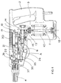
- Figure 1 shows, in a side view and partly opened up in greatly simplified representation, an electric tool in the form of a rotary hammer.
- Figure 2 shows, in an enlarged partial view, an area of the rotary hammer essentially identified by the circle A.
- Figure 3 shows, in a part section, elements of the switch-over device of the rotary hammer from Figures 1 and 2, the first axial position being represented in the upper half and the second axial position in the lower half.
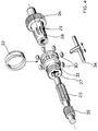
- Figure 4 shows, in exploded, enlarged partial view, elements of the switch-over device, containing the coupling, of the rotary hammer according to Figures 1 to 3.
- Figure 5 shows, in section, another version of a switch-over device.
- Figure 6 shows, in an exploded view, the parts of the switch-over device from Figure 5.
- the rotary hammer represented in Figure 1 has a housing 1, which comprises in the rear zone a handle section 2 adjacent to which is formed a handle opening 3. Located at the front end of the rotary hammer is a diagrammatically represented tool holder 4 into which a hammer bit is inserted during operation.
- an electric motor 10 whose electrical connections are not represented and which has on its armature shaft 11 a conventional fan wheel 12.
- armature shaft 11 Provided at the end of the armature shaft 11 opposite the fan wheel is a bevel gear 13 which meshes with a gear 14 which is secured non-rotatably on an intermediate shaft 15 which extends perpendicular to the armature shaft 11 and parallel to the centre axis of the tool holder 4.
- a wobble plate drive with a hub body 17 and a wobble finger 18 secured rotatable relative to said hub body.
- the wobble finger 18 is connected to the rear end of a hollow piston 19 which is axially reciprocable in a stationary guide tube 20 and in which is located a ram 21 which is reciprocated pneumatically, i.e. by alternating build-up of overpressure and underpressure at its rear in known manner.
- the ram 21 transmits impacts via an anvil 22 onto the rear end of a hammer bit, not represented, which is inserted into the tool holder 4.
- a pinion 16 Formed at the front end of the intermediate shaft 15 is a pinion 16 which meshes with a gear formed at a sleeve-like coupling part 26.
- the coupling part 26 sits, in a manner to be described, on a coupling shaft 25 which extends parallel to the intermediate shaft 15 and on which a gear 35 is secured non-rotatable and axially non-displaceable.
- the gear 35 meshes with a gear 36 which is formed on a spindle 37, so that rotation of the coupling shaft 25 effects a rotation of the gear 36 and thus of the hammer bit inserted into the tool holder 4.
- the coupling part 26 is mounted on the coupling shaft 25 and is axially non-displaceable, but freely rotatable, on the shaft 25.
- a second coupling part 27 which is essentially sleeve-like.
- This coupling part 27 is, as Figures 3 and 4 in particular show, coupled via splined portion of the coupling shaft 25 non-rotatably and axially displaceable with the latter, a coil spring spring-loading the second coupling part 27 in the direction of the first coupling part 26.
- a slide element 34 indicated diagrammatically in Figure 4 and actuatable by the user, engages with an annular groove 33 of the second coupling part 27 in order to displace this between two operating positions which are to be described.
- the second coupling part 27 comprises radial apertures into which are inserted locking elements in the form of cylindrical roller bodies 30 (Figure 4).
- These roller bodies 30 are spring-loaded inwards by means of a surrounding, slotted spring ring 32 and are located, in one end-position of the second coupling part 27, adjacent locking recesses 29 of the first coupling part 26 and, in another end-position, engage with a smooth rotating surface 28 of the first coupling part 26 and, in another end-position, engage with a smooth rotating surface 28 of the first coupling part 26 which is axially offset from the locking recesses 29.
- the axially extending, elongated locking recesses 29 lie with their groove bottom on the same peripheral circle about the rotation axis of the coupling shaft 25 as the smooth rotating surface 28 and are open towards the latter.
- the first coupling part 26 is caused to rotate on the coupling shaft 25 but the roller bodies 30 rolling on the smooth rotating surface 28.
- the coupling shaft 25 is therefore not driven and the tool holder 4 does not perform a rotary movement, i.e. the intermediate shaft 15 merely drives the hammer mechanism, so that the ram 21 generates impacts for the blows for the hammer bit, i.e. the rotary hammer works in pure hammer mode.
- the roller bodies 30 are moved into the locking recesses 29. With this displacement the roller bodies 30 can, upon alignment relative to the locking recesses 29, enter the latter without hindrance, as the locking recesses 29 are open at the ends facing the smooth rotating surface 28. If there is no precise alignment, it can happen that the roller bodies 30 enter the areas between the locking recesses 29 and are radially pressed outwards. With the first relative rotation of the two coupling parts 26, 27, however, the roller bodies 30 will then, because of the forces of the spring ring 32 acting on them enter the locking recesses 29.
- the second coupling part 27 is now coupled non-rotatably with the first coupling part 26, so that, when intermediate shaft 15 is driven, the rotation of the first coupling part 26 which then occurs results in a corresponding rotation of the second coupling part 27 and thus of the coupling shaft 25 which is non-rotatably connected to this.
- a rotation of the tool holder 4 is effected via the gears 35 and 36, so that the rotary hammer works in combined drill and hammer mode.
- connection of the two coupling parts 26 and 27 acts as an overload coupling, as the roller bodies 30 are pressed radially outwards against the forces of the spring ring 32 and run over the locking recesses 29, i.e. the driven first coupling part 26 rotates vis-à-vis the second coupling part 27 when a pre-set torque is exceeded.
- FIG. 5 and 6 Represented in Figures 5 and 6 is a switch-over device for the switch-over between two rotation speeds of a rotary hammer or of a power drill. Included in this switch-over device for the changing of operating conditions are parts which have essentially the same function as those from the embodiment according to Figures 1 to 3, and whose reference numerals are the same except that they have been increased by 100.
- Two gears 126, 126' are arranged freely rotatable on a coupling shaft 125, which can correspond to the coupling shaft 25 in a rotary hammer according to Figures 1 and 2 but can also be a drilling spindle in a drill according to German Patent Application P 35 40 605 mentioned above.
- a switching sleeve 127 which forms a first coupling part and which, through a splined profile design of the coupling shaft 125 and a corresponding shape of the continuous bore of the switching sleeve 127, sits non-rotatably on the coupling shaft 125, but can be displaced on the latter between a position as is indicated in the upper half of Figure 4 and a position as is shown in the lower half of Figure 4.
- the switching sleeve 127 has a peripheral groove 133 in which an eccentric pin of a normal rotatable changeover switch 134 ( Figure 6), to be actuated by the user, engages.
- the switching sleeve 127 has axial continuous bores in which spacing pins 143 are displaceably arranged, which pins lie with their ends against the adjacent surfaces of the gears 126, 126' and thus ensure that the gears 126, 126' are always at the same distance and abut the assembly ring 141 positioned by a spring ring 142 and the collar 140 of the coupling shaft 125, respectively.
- Gear 126 meshes with a gear 116 and gear 126' with a gear 116', which are both provided on the intermediate shaft 115, which is coupled with a drive via a gear 114. A rotation of the intermediate shaft 115 thus effects a rotation of both gears 126, 126'.
- both gears 126, 126' forming second coupling parts, in the tooth-free sections which in each case extend in the direction of the opposite gear, are radial receiving bores into which the compression springs 131, 131' are inserted, which springs are supported on one side at the bottom of the receiving bore and on the other at an outside-lying, spherical roller body 130, 130'.
- the switching sleeve 127 has annular extensions one of which, starting from the middle zone of switching sleeve 127, extends in the direction of gear 126 and comprises, at its inner surface, locking recesses 129 and, adjacent thereto, a smooth rotating surface, while the opposite annular extension, starting from the middle zone of switching sleeve 127, has locking recesses 129' and a smooth rotating surface 128'.
- the extensions are so dimensioned that they always cover the roller bodies 130, 130'.
- roller bodies 130 of gear 126 engage with the locking recesses 129 open to the rotating surface 128 and the roller bodies 130' of gear 126' are supported at the smooth rotating surface 128'.
- roller bodies 130 lie on the smooth rotating surface 128, while roller bodies 130' engage with the locking recesses 129' open to the rotating surface 129'.
- gear 126 In the first-mentioned position, gear 126 is thus coupled with the switching sleeve 127 and therefore unrotatable connected with the coupling shaft 125 so that, upon rotation of the intermediate shaft 115, the coupling shaft 125 is driven via gear 126, while gear 126' idles on the coupling shaft 125.
- gear 126' In the second-mentioned position, gear 126' is connected with the coupling shaft 125, while gear 126 idles, producing a speed for the coupling shaft 125 which is different from that in the case of the first-mentioned position.
- the annular extensions of the switching sleeve 127 are so dimensioned that the roller bodies of one gear are supported at the associated smooth rotating surface when the roller bodies of the other gear engage with the associated locking recesses, which ensures that only one of the gears 126, 126' is ever non-rotatably coupled with the coupling shaft 125.
- the dimensions are preferably so chosen that the roller bodies 130, 130' of both gears 126, 126' engage with the smooth rotating surfaces 128, 128' over a short section in the middle or transitional position of the switching sleeve 127, so that a times during the switch-over process, neither of the two gears 126, 126' is non-rotatably coupled with coupling shaft 125.
- the switching sleeve 127 If the switching sleeve 127 is moved into an end-position, it can happen that its locking recesses are not precisely aligned in peripheral direction relative to the roller bodies to be received.
- roller bodies are then, as indicated in the lower half of Figure 5 for roller body 130', pushed deeper into the receiving bores by the webs between the adjacent locking recesses 129', and so do not hinder the displacement of the switching sleeve 127 into its end-position.
- the roller bodies 130' snap, as a result of the effects of the springs 131', into the locking recesses 129' which are coming into alignment with them, and the coupling between switching sleeve 127 and gear is effected.
Landscapes
- Engineering & Computer Science (AREA)
- Mechanical Engineering (AREA)
- General Engineering & Computer Science (AREA)
- Percussive Tools And Related Accessories (AREA)
Claims (10)
- Un outil entraîné par moteur muni d'un porte-outil (4) entraîné en rotation et d'un dispositif de commutation, comprenant au moins un accouplement limiteur de charge, pour effectuer une commutation entre diverses conditions et/ou modes de fonctionnement, dans lequel un premier organe d'accouplement (26, 127), monté rotatif autour d'un axe de rotation, comporte des évidements de verrouillage (29; 129, 129') dans lesquels pénètrent des organes de roulement (30; 130. 130') servant d'éléments de verrouillage lorsqu'ils sont en prise, qui sont retenus, de manière fixe dans la direction circonférentielle mais mobiles pour venir dans et hors d'engagement avec les évidements de verrouillage (29; 129, 129'), dans un second organe d'accouplement (27; 126, 126') qui est monté rotatif autour de l'axe de rotation, caractérisé en ce que les premier et second organes d'accouplement sont mobiles l'un par rapport à l'autre entre une première position axiale, dans laquelle les organes de roulement (30; 130, 130') peuvent être amenés à s'engager dans les évidements de verrouillage (29; 129, 129') sous l'action d'une force élastique, et une seconde position axiale et en ce que, dans la seconde position axiale, les organes de roulement (30; 130, 130') viennent en appui contre une surface rotative lisse (28; 128, 128'), axialement décalée par rapport aux évidements de verrouillage (29; 129, 129'), du premier organe d'accouplement (26; 127).
- Outil entraîné par moteur selon la revendication 1, caractérisé en ce que le premier organe d'accouplement (26; 126, 126') est entraîné par un arbre intermédiaire (15; 115) et le second organe d'accouplement (27; 127) est accouplé au porte-outil (4).
- Outil entraîné par moteur selon la revendication 2, caractérisé en ce que le premier organe d'accouplement (26; 126, 126') est du type manchon et comporte, au voisinage d'une première extrémité, un engrenage qui engrène avec un engrenage (16) porté par l'arbre intermédiaire, en ce que la surface rotative (28) est formée au voisinage de l'extrémité opposée du premier organe d'accouplement (28) et en ce que les évidements de verrouillage (29) sont disposés entre la surface rotative (28) et l'engrenage.
- Outil entraîné par moteur selon la revendication 2 ou 3, caractérisé en ce que le second organe d'accouplement (27) est monté solidaire en rotation et mobile entre des première et seconde positions axiales sur un arbre d'accouplement (25) qui est accouplé au porte-outil (4) par l'intermédiaire d'un train d'engrenages (35, 36).
- Outil entraîné par moteur selon la revendication 4, caractérisé en ce que le premier organe d'accouplement (26) est monté à rotation libre et axialement fixe sur l'arbre d'accouplement (25).
- Outil entraîné par moteur selon l'une des revendications 1 à 5, caractérisé en ce que la distance radiale entre la surface rotative (28) du premier organe d'accouplement (26) et l'axe de rotation n'est pas supérieure à la distance radiale entre le fond des évidements de verrouillage (29) et l'axe de rotation.
- Outil entraîné par moteur selon l'une des revendications 1 à 5, caractérisé en ce que les évidements de verrouillage (29) sont ouverts aux extrémités faisant face à la surface rotative (28).
- Outil entraîné par moteur selon la revendication 1 ou 2, caractérisé en ce que le dispositif de commutation comporte deux engrenages (126, 126') montés à rotation libre sur un arbre d'accouplement (125), chacun des engrenages formant un second organe d'accouplement, lesdits engrenages ayant des diamètres externes différents et étant constamment en prise avec des engrenages calés sur un arbre intermédiaire et en ce qu'un manchon de commutation (127) monté sur l'arbre d'accouplement, solidaire en rotation de ce dernier et axialement mobile entre les engrenages, forme le premier organe d'accouplement et comporte, à chacune de ses extrémités axialement opposées, une surface rotative intérieure lisse (128, 128') et des évidements de verrouillage (129, 129') situés à l'intérieur par rapport à la surface (128, 128') pour recevoir les organes de roulement coopérants (130, 130') prévus dans l'engrenage correspondant (126, 126').
- Outil entraîné par moteur selon la revendication 8, caractérisé en ce que les engrenages (126, 126') sont espacés l'un de l'autre sur l'arbre (125) d'une manière telle que, lorsque les organes de roulement (par exemple, 130) d'un engrenage (126) se trouvent dans la région des évidements de verrouillage correspondants (129) du manchon de commutation (127), les organes de roulement (130') reposent sur la surface intérieure rotative lisse correspondante (128').
- Outil entraîné par moteur selon la revendication 8 ou 9, caractérisé en ce que les évidements de verrouillage (129, 129') sont ouverts aux extrémités qui font face à la surface rotative correspondante (128, 128').
Applications Claiming Priority (2)
| Application Number | Priority Date | Filing Date | Title |
|---|---|---|---|
| DE4302083 | 1993-01-19 | ||
| DE4302083A DE4302083A1 (de) | 1993-01-19 | 1993-01-19 | Kraftgetriebenes Werkzeug, insbesondere Elektrowerkzeug |
Publications (2)
| Publication Number | Publication Date |
|---|---|
| EP0608083A1 EP0608083A1 (fr) | 1994-07-27 |
| EP0608083B1 true EP0608083B1 (fr) | 1996-10-09 |
Family
ID=6478952
Family Applications (1)
| Application Number | Title | Priority Date | Filing Date |
|---|---|---|---|
| EP94300281A Expired - Lifetime EP0608083B1 (fr) | 1993-01-19 | 1994-01-14 | Outil entraîné par moteur, en particulier un outil électrique |
Country Status (2)
| Country | Link |
|---|---|
| EP (1) | EP0608083B1 (fr) |
| DE (2) | DE4302083A1 (fr) |
Cited By (1)
| Publication number | Priority date | Publication date | Assignee | Title |
|---|---|---|---|---|
| CN102076994A (zh) * | 2008-06-30 | 2011-05-25 | 罗伯特·博世有限公司 | 多档传动装置和工具机 |
Families Citing this family (18)
| Publication number | Priority date | Publication date | Assignee | Title |
|---|---|---|---|---|
| DE19716976A1 (de) * | 1997-04-23 | 1998-10-29 | Bosch Gmbh Robert | Elektrowerkzeugmaschine |
| US6102632A (en) * | 1998-04-23 | 2000-08-15 | Black & Decker Inc. | Two speed right angle drill |
| DE10106034B4 (de) | 2001-02-09 | 2009-11-26 | Robert Bosch Gmbh | Handwerkzeugmaschine |
| DE10131220C1 (de) * | 2001-06-28 | 2003-03-06 | Metabowerke Gmbh | Elektrohandwerkzeug mit einer Überlastkupplung |
| SE520640C2 (sv) | 2001-10-16 | 2003-08-05 | Atlas Copco Tools Ab | Handhållet kraftverktyg med en roterande utgående axel |
| GB0505457D0 (en) * | 2005-03-18 | 2005-04-20 | Black & Decker Inc | Torque overload clutch for rotary hammer drills |
| EP1702723B1 (fr) | 2005-03-18 | 2014-04-02 | Black & Decker, Inc. | Embrayage à surcharge de couple pour outil motorisé |
| DE102006009922A1 (de) * | 2006-03-03 | 2007-09-06 | Robert Bosch Gmbh | Schaltbare Kupplung für ein Elektrohandwerkzeug |
| DE102007014756A1 (de) * | 2007-03-28 | 2008-10-02 | Robert Bosch Gmbh | Handwerkzeug |
| US7793560B2 (en) | 2007-09-11 | 2010-09-14 | Black & Decker Inc. | Transmission and variable radially expanding spring clutch assembly |
| DE102008002589A1 (de) * | 2008-06-24 | 2009-12-31 | Robert Bosch Gmbh | Werkzeugmaschine mit einer einstellbaren Kupplungsvorrichtung und Verfahren zum Betrieb |
| US8540580B2 (en) * | 2009-08-12 | 2013-09-24 | Black & Decker Inc. | Tool bit or tool holder for power tool |
| CN104455396B (zh) * | 2014-11-17 | 2016-08-24 | 张家港市创基机械设备制造有限公司 | 四功能电锤中的换档机构 |
| WO2018085142A1 (fr) | 2016-11-04 | 2018-05-11 | Milwaukee Electric Tool Corporation | Mécanisme d'embrayage destiné à un outil électrique tournant |
| JP7465647B2 (ja) * | 2019-10-21 | 2024-04-11 | 株式会社マキタ | ハンマドリル |
| US11529727B2 (en) | 2019-10-21 | 2022-12-20 | Makita Corporation | Power tool having hammer mechanism |
| CN112091279B (zh) * | 2020-10-13 | 2021-07-30 | 永康市富尔达工具有限公司 | 一种具有卡死保护结构的冲击钻 |
| US20230069811A9 (en) * | 2020-12-17 | 2023-03-02 | Sps Technologies, Llc | Two-piece blind fastener and installation tool |
Family Cites Families (18)
| Publication number | Priority date | Publication date | Assignee | Title |
|---|---|---|---|---|
| US1434970A (en) * | 1918-12-17 | 1922-11-07 | Emma H Taylor | Clutch |
| CH175749A (fr) * | 1933-01-25 | 1935-03-15 | Bailleul Louis Pierre Alexandr | Dispositif de liaison axiale entre organes concentriques. |
| US2544809A (en) * | 1945-04-10 | 1951-03-13 | American Viscose Corp | Overload release clutch |
| US2618940A (en) * | 1948-06-25 | 1952-11-25 | Wyzenbeek Andrew | Flexible shaft handpiece coupling |
| US2886075A (en) * | 1956-10-23 | 1959-05-12 | Thor Power Tool Co | Torque release clutch drive mechanism for power operated screw drivers and the like |
| DE1903434U (de) * | 1964-03-07 | 1964-10-29 | Duss Maschf | Von hand gefuehrte tragbare elektrisch angetriebene werkzeugmaschine zur steinbearbeitung. |
| GB1522699A (en) * | 1974-12-19 | 1978-08-23 | Rockwell International Corp | Power tool with torque limiting device |
| DE2828722A1 (de) * | 1978-06-30 | 1980-01-10 | Hurth Masch Zahnrad Carl | Schaltbare reibungskupplung fuer zahnradgetriebe |
| DE3235544A1 (de) * | 1982-09-25 | 1984-03-29 | Robert Bosch Gmbh, 7000 Stuttgart | Bohrhammer |
| DE3503507A1 (de) * | 1985-02-02 | 1986-08-07 | Robert Bosch Gmbh, 7000 Stuttgart | Bohrhammer |
| DE3537254A1 (de) * | 1985-10-19 | 1987-04-23 | Licentia Gmbh | Elektropneumatischer drehschlagbohrhammer zum bearbeiten von gestein, beton und aehnlichem material |
| DE3540605A1 (de) | 1985-11-15 | 1987-05-21 | Licentia Gmbh | Elektrowerkzeug mit einem zweiganggetriebe |
| DE3618024A1 (de) * | 1986-05-28 | 1987-12-03 | Hilti Ag | Elektrowerkzeug mit schaltkupplung |
| JPH0639899Y2 (ja) * | 1986-08-08 | 1994-10-19 | 株式会社マキタ | 回転電動工具におけるトルク調整装置 |
| DE3804414A1 (de) * | 1988-02-12 | 1989-08-24 | Hilti Ag | Bohrhammer mit kugelrastkupplung |
| DE3807308A1 (de) * | 1988-03-05 | 1989-09-14 | Licentia Gmbh | Sicherheitsrutschkupplung eines elektrowerkzeuges mit radialer wirkungsweise |
| DE3844311A1 (de) * | 1988-12-30 | 1990-07-05 | Bosch Gmbh Robert | Bohrmaschine |
| DE4113649A1 (de) * | 1991-04-26 | 1992-10-29 | Bosch Gmbh Robert | Handwerkzeugmaschine |
-
1993
- 1993-01-19 DE DE4302083A patent/DE4302083A1/de not_active Withdrawn
-
1994
- 1994-01-14 DE DE69400644T patent/DE69400644T2/de not_active Expired - Lifetime
- 1994-01-14 EP EP94300281A patent/EP0608083B1/fr not_active Expired - Lifetime
Cited By (1)
| Publication number | Priority date | Publication date | Assignee | Title |
|---|---|---|---|---|
| CN102076994A (zh) * | 2008-06-30 | 2011-05-25 | 罗伯特·博世有限公司 | 多档传动装置和工具机 |
Also Published As
| Publication number | Publication date |
|---|---|
| DE4302083A1 (de) | 1994-07-21 |
| DE69400644T2 (de) | 1997-02-13 |
| DE69400644D1 (de) | 1996-11-14 |
| EP0608083A1 (fr) | 1994-07-27 |
Similar Documents
| Publication | Publication Date | Title |
|---|---|---|
| EP0608083B1 (fr) | Outil entraîné par moteur, en particulier un outil électrique | |
| US5711380A (en) | Rotate percussion hammer/drill shift device | |
| US6510903B2 (en) | Combination electrical hand-held tool | |
| EP0775555B1 (fr) | Marteau de forage rotatif | |
| US4763733A (en) | Hammer drill with rotational lock | |
| US6460627B1 (en) | Drilling and/or chiseling device | |
| US4446931A (en) | Power driven hammer drill | |
| CN100556593C (zh) | 手持式工具机 | |
| US5588496A (en) | Slip clutch arrangement for power tool | |
| EP2062697B1 (fr) | Marteau perforateur avec collier pour le mode | |
| EP1114700B1 (fr) | Mécanisme d'entraînement de came | |
| USRE40643E1 (en) | Rotary hammer | |
| EP2062695B1 (fr) | Sous-ensemble de transmission pour machine de forage à modes multiples | |
| US6015017A (en) | Rotary hammer | |
| EP2062693B1 (fr) | Marteau perforateur doté d'une structure dure de support du marteau | |
| EP2062670B1 (fr) | Perceuse à modes multiples dotée d'un agencement de commutation électronique | |
| EP2062696B1 (fr) | Marteau perforateur à modes multiples doté d'un dispositif de verrouillage | |
| US4967888A (en) | Safety clutch for motor-operated hand tool | |
| GB2418634A (en) | Power tool comprising a drive that can be switched over between drilling, percussion drilling and chiselling operating modes | |
| JP2003236769A (ja) | 手工具装置の作動モード切替ユニット | |
| US9010456B2 (en) | Hand-held power tool | |
| EP3808478B1 (fr) | Foret à percussion | |
| JP2703637B2 (ja) | ドリルハンマ | |
| JPS63162169A (ja) | 手持ち式装置 | |
| JPS6218284B2 (fr) |
Legal Events
| Date | Code | Title | Description |
|---|---|---|---|
| PUAI | Public reference made under article 153(3) epc to a published international application that has entered the european phase |
Free format text: ORIGINAL CODE: 0009012 |
|
| AK | Designated contracting states |
Kind code of ref document: A1 Designated state(s): CH DE FR GB IT LI NL |
|
| 17P | Request for examination filed |
Effective date: 19950123 |
|
| 17Q | First examination report despatched |
Effective date: 19951201 |
|
| GRAH | Despatch of communication of intention to grant a patent |
Free format text: ORIGINAL CODE: EPIDOS IGRA |
|
| GRAH | Despatch of communication of intention to grant a patent |
Free format text: ORIGINAL CODE: EPIDOS IGRA |
|
| GRAA | (expected) grant |
Free format text: ORIGINAL CODE: 0009210 |
|
| AK | Designated contracting states |
Kind code of ref document: B1 Designated state(s): CH DE FR GB IT LI NL |
|
| PG25 | Lapsed in a contracting state [announced via postgrant information from national office to epo] |
Ref country code: NL Free format text: LAPSE BECAUSE OF FAILURE TO SUBMIT A TRANSLATION OF THE DESCRIPTION OR TO PAY THE FEE WITHIN THE PRESCRIBED TIME-LIMIT Effective date: 19961009 Ref country code: FR Effective date: 19961009 |
|
| REG | Reference to a national code |
Ref country code: CH Ref legal event code: NV Representative=s name: PATENTANWALTSBUREAU R. A. MASPOLI |
|
| ITF | It: translation for a ep patent filed |
Owner name: GUZZI E RAVIZZA S.R.L. |
|
| REF | Corresponds to: |
Ref document number: 69400644 Country of ref document: DE Date of ref document: 19961114 |
|
| NLV1 | Nl: lapsed or annulled due to failure to fulfill the requirements of art. 29p and 29m of the patents act | ||
| EN | Fr: translation not filed | ||
| PLBE | No opposition filed within time limit |
Free format text: ORIGINAL CODE: 0009261 |
|
| STAA | Information on the status of an ep patent application or granted ep patent |
Free format text: STATUS: NO OPPOSITION FILED WITHIN TIME LIMIT |
|
| 26N | No opposition filed | ||
| REG | Reference to a national code |
Ref country code: GB Ref legal event code: IF02 |
|
| PGFP | Annual fee paid to national office [announced via postgrant information from national office to epo] |
Ref country code: CH Payment date: 20100125 Year of fee payment: 17 |
|
| REG | Reference to a national code |
Ref country code: CH Ref legal event code: PL |
|
| PG25 | Lapsed in a contracting state [announced via postgrant information from national office to epo] |
Ref country code: LI Free format text: LAPSE BECAUSE OF NON-PAYMENT OF DUE FEES Effective date: 20110131 Ref country code: CH Free format text: LAPSE BECAUSE OF NON-PAYMENT OF DUE FEES Effective date: 20110131 |
|
| PGFP | Annual fee paid to national office [announced via postgrant information from national office to epo] |
Ref country code: DE Payment date: 20120127 Year of fee payment: 19 |
|
| PGFP | Annual fee paid to national office [announced via postgrant information from national office to epo] |
Ref country code: GB Payment date: 20120126 Year of fee payment: 19 Ref country code: IT Payment date: 20120124 Year of fee payment: 19 |
|
| GBPC | Gb: european patent ceased through non-payment of renewal fee |
Effective date: 20130114 |
|
| PG25 | Lapsed in a contracting state [announced via postgrant information from national office to epo] |
Ref country code: DE Free format text: LAPSE BECAUSE OF NON-PAYMENT OF DUE FEES Effective date: 20130801 |
|
| REG | Reference to a national code |
Ref country code: DE Ref legal event code: R119 Ref document number: 69400644 Country of ref document: DE Effective date: 20130801 |
|
| PG25 | Lapsed in a contracting state [announced via postgrant information from national office to epo] |
Ref country code: GB Free format text: LAPSE BECAUSE OF NON-PAYMENT OF DUE FEES Effective date: 20130114 |
|
| PG25 | Lapsed in a contracting state [announced via postgrant information from national office to epo] |
Ref country code: IT Free format text: LAPSE BECAUSE OF NON-PAYMENT OF DUE FEES Effective date: 20130114 |