EP0606876A1 - Holder for a vehicle number plate - Google Patents
Holder for a vehicle number plate Download PDFInfo
- Publication number
- EP0606876A1 EP0606876A1 EP94100267A EP94100267A EP0606876A1 EP 0606876 A1 EP0606876 A1 EP 0606876A1 EP 94100267 A EP94100267 A EP 94100267A EP 94100267 A EP94100267 A EP 94100267A EP 0606876 A1 EP0606876 A1 EP 0606876A1
- Authority
- EP
- European Patent Office
- Prior art keywords
- clamping element
- holder according
- plate
- frame
- cylindrical body
- Prior art date
- Legal status (The legal status is an assumption and is not a legal conclusion. Google has not performed a legal analysis and makes no representation as to the accuracy of the status listed.)
- Granted
Links
Images

Classifications
-
- B—PERFORMING OPERATIONS; TRANSPORTING
- B60—VEHICLES IN GENERAL
- B60R—VEHICLES, VEHICLE FITTINGS, OR VEHICLE PARTS, NOT OTHERWISE PROVIDED FOR
- B60R13/00—Elements for body-finishing, identifying, or decorating; Arrangements or adaptations for advertising purposes
- B60R13/10—Registration, licensing, or like devices
- B60R13/105—Licence- or registration plates, provided with mounting means, e.g. frames, holders, retainers, brackets
-
- G—PHYSICS
- G09—EDUCATION; CRYPTOGRAPHY; DISPLAY; ADVERTISING; SEALS
- G09F—DISPLAYING; ADVERTISING; SIGNS; LABELS OR NAME-PLATES; SEALS
- G09F7/00—Signs, name or number plates, letters, numerals, or symbols; Panels or boards
- G09F7/18—Means for attaching signs, plates, panels, or boards to a supporting structure
- G09F2007/1843—Frames or housings to hold signs
-
- G—PHYSICS
- G09—EDUCATION; CRYPTOGRAPHY; DISPLAY; ADVERTISING; SEALS
- G09F—DISPLAYING; ADVERTISING; SIGNS; LABELS OR NAME-PLATES; SEALS
- G09F7/00—Signs, name or number plates, letters, numerals, or symbols; Panels or boards
- G09F7/18—Means for attaching signs, plates, panels, or boards to a supporting structure
- G09F2007/1873—Means for attaching signs, plates, panels, or boards to a supporting structure characterised by the type of sign
- G09F2007/1895—Licence number plates
Abstract
Description
Die Erfindung betrifft eine Halterung für ein Kennzeichenschild eines Fahrzeugs, insbesondere eines Kraftfahrzeugs, bestehend aus einer an dem Fahrzeug fixierbaren Platte mit einem in etwa der Kontur des Schildes nachempfundenen Rahmen.The invention relates to a holder for a license plate of a vehicle, in particular a motor vehicle, consisting of a plate which can be fixed to the vehicle and has a frame which roughly mimics the contour of the plate.
Halterungen der eingangs genannten Art sind hinlänglich bekannt; so ist beispielsweise aus dem DE-GM 780 14 237 eine Halterung für ein Kennzeichenschild bekannt, wobei das Kennzeichenschild durch auf einen Hauptrahmen aufsteckbare Haltestücke fixierbar ist, wobei die Haltestücke durch eine formschlüssige Verbindung lösbar in dem Hauptrahmen verbunden sind. Als Variante wird angeboten, auf einen ersten Hauptrahmen einen zweiten Rahmen aufzusetzen und hierdurch das Kennzeichenschild nach Auflage auf die Platte zu fixieren. Nachteilig hieran ist, daß das Kennzeichenschild an zumindest zwei gegenüberliegenden Rahmenholmen fixiert werden muß. Durch mindestens vier Haltestücke bzw. einen auf den Hauptrahmen aufsetzbaren zweiten Rahmen erhöhen sich die Produktionskosten einer derartigen Halterung für ein Kennzeichenschild; darüber hinaus wird auch die Montage aufwendiger.Brackets of the type mentioned are well known; For example, from DE-GM 780 14 237, a holder for a license plate is known, the license plate being fixable by holding pieces that can be plugged onto a main frame, the holding pieces being detachably connected in the main frame by a positive connection. As a variant, it is offered to place a second frame on a first main frame and thereby fix the license plate after placing it on the plate. The disadvantage of this is that the license plate must be fixed to at least two opposite frame bars. By at least four holding pieces or one on the Main frame attachable second frame increases the production cost of such a holder for a license plate; in addition, assembly is also more complex.
Der Erfindung liegt daher die Aufgabe zugrunde, eine Halterung für ein Kennzeichenschild zu schaffen, das preiswert in der Herstellung und eine einfache Montage zuläßt.The invention is therefore based on the object of providing a holder for a license plate which allows inexpensive manufacture and simple assembly.
Erfindungsgemäß wird die Aufgabe dadurch gelöst, daß mindestens ein Rahmenholm eine parallel zur Platte verlaufende Nut und der gegenüberliegende Rahmenholm mindestens ein Klemmelement zur Fixierung des Schildes aufweist. D.h., daß das Kennzeichenschild sowohl durch die vorzugsweise am oberen horizontal verlaufenden Rahmenholm parallel zur Platte verlaufenden Nut, als auch durch mindestens ein, vorzugsweise jedoch zwei Klemmelemente am gegenüberliegenden Rahmenholm gehalten wird. Der Abstand zwischen den beiden Innenkanten der sich gegenüberliegenden Rahmenholme muß hierbei derart sein, daß er geringer ist als die Breite oder die Länge des Kennzeichenschildes, je nachdem durch welche Rahmenholme das Schild fixiert wird, so daß das Kennzeichenschild, selbst wenn es an dem einen Rahmenholm anliegt, noch von der Nut im gegenüberliegenden Holm erfaßt wird.According to the invention the object is achieved in that at least one frame spar has a groove running parallel to the plate and the opposite frame spar has at least one clamping element for fixing the shield. This means that the number plate is held both by the groove running preferably parallel to the plate on the upper horizontally extending frame spar, and by at least one, but preferably two, clamping elements on the opposite frame spar. The distance between the two inner edges of the opposite frame spars must be such that it is less than the width or length of the license plate, depending on which frame spars the plate is fixed, so that the license plate, even if it is on one frame spar is still detected by the groove in the opposite spar.
Nach einer Ausführungsform weist das Klemmelement einen Klemmkopf und ein Rastelement zur Aufnahme durch den Rahmenholm auf. Im einzelnen besitzt das Rastelement einen Rastkopf, der von einer im Rahmenholm angeordneten öffnung formschlüssig und unlösbar aufgenommen wird. Dadurch, daß die Klemmelemente unlösbar auf dem Rahmenholm fixiert sind, wird der Diebstahl der Kennzeichenschilder erschwert.According to one embodiment, the clamping element has a clamping head and a locking element for receiving by the frame spar. In particular, the locking element has a locking head which is received in a form-fitting and non-detachable manner by an opening arranged in the frame rail. The fact that the clamping elements are permanently attached to the frame spar makes the theft of the license plates more difficult.
Nach einer zweiten Ausführungsform ist das Klemmelement parallel zur Platte verschieblich in einer in dem Rahmenholm angeordneten Führungsnut gehalten, wobei zur Verschiebung des Klemmelementes in Richtung des Schildes ein Schubglied vorgesehen ist. Im Gegensatz zur ersten Ausführungsform sind hier die Klemmittel zur Fixierung des Kennzeichenschildes bei der Montage des Schildes mit der Halterung verbunden, was die Montage erheblich vereinfacht. Im einzelnen ist das Schubglied als zylindrischer Körper ausgebildet, der von einer im Rahmenholm angeordneten entsprechenden Bohrung aufgenommen wird, wobei der zylindrische Körper eine radiale Nut aufweist, die sich nach einer vorteilhaften Ausbildung über einen Teil des Umfangs des zylindrischen Körpers erstreckt, so daß sich ein exzentrischer Abschnitt ergibt, durch den das Klemmelement erfaßt wird. Das Klemmelement selbst besitzt eine Aussparung zur Aufnahme des exzentrischen Abschnittes, wobei die Größe der Aussparung kleiner als der Querschnitt des zylindrischen Körpers, aber größer als der Querschnitt des exzentrischen Abschnitts ist; vorzugsweise weist die Aussparung die Form eines Ovals auf. D.h., daß bei Drehung des zylindrischen Körpers, und somit bei Drehung des exzentrischen Abschnitts in der Aussparung des Klemmelements das Klemmelement in der Führungsnut parallel verschiebbar ist. Hierdurch wird erreicht, daß das Klemmelement einmal auf das Kennzeichenschild zu und bei entsprechend gegenläufiger bzw. weiterer Drehung von dem Kennzeichenschild wegbewegt werden kann. Die Bewegung des Klemmelements in Richtung des Schildes ist derart, daß es das Schild zur Fixierung in der einen Endlage partiell überlappt. Um die Montage zu ermöglichen, schließt sich an die Aussparung ein Schlitz an, dessen Breite in etwa dem Querschnitt des exzentrischen Abschnitts entspricht. Durch diesen Schlitz wird das Klemmelement in die Führungsnut eingeschoben, wobei hierbei der exzentrische Abschnitt mit seiner Schmalseite parallel zum Schlitz liegt.According to a second embodiment, the clamping element is displaceably held parallel to the plate in a guide groove arranged in the frame spar, a pushing element being provided for displacing the clamping element in the direction of the shield. In contrast to the first embodiment here the clamping means for fixing the license plate when mounting the plate connected to the bracket, which considerably simplifies the assembly. In particular, the thrust member is designed as a cylindrical body which is received by a corresponding bore arranged in the frame spar, the cylindrical body having a radial groove which, according to an advantageous embodiment, extends over part of the circumference of the cylindrical body, so that a Eccentric section results through which the clamping element is detected. The clamping element itself has a recess for receiving the eccentric section, the size of the recess being smaller than the cross section of the cylindrical body, but larger than the cross section of the eccentric section; the recess preferably has the shape of an oval. This means that when the cylindrical body rotates, and thus when the eccentric section rotates in the recess of the clamping element, the clamping element can be displaced in parallel in the guide groove. This ensures that the clamping element can be moved towards the license plate once and away from the license plate with corresponding opposite or further rotation. The movement of the clamping element in the direction of the shield is such that it partially overlaps the shield for fixing in one end position. In order to enable assembly, a slot adjoins the recess, the width of which corresponds approximately to the cross section of the eccentric section. Through this slot, the clamping element is inserted into the guide groove, the narrow side of the eccentric section being parallel to the slot.
Anhand der nachstehenden Zeichnungen sind die beiden Ausführungsformen beispielhaft näher erläutert.
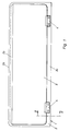
- Fig. 1
- zeigt die erste Ausführungsform einer Halterung für Kennzeichenschilder in einer Draufsicht, wobei die Klemmelemente aufsteckbar sind;
- Fig. 2
- zeigt einen Schnitt gemäß der Linie II-II aus Fig. 1;
- Fig. 3
- zeigt das Klemmelement in einer Draufsicht;
- Fig. 4
- zeigt eine Seitenansicht des Klemmelementes;
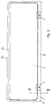
- Fig. 5
- zeigt die zweite Ausführungsform in einer Draufsicht, wobei die Klemmelemente verschiebbar im Rahmenholm angeordnet sind;
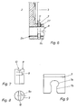
- Fig. 6
- zeigt einen Schnitt gemäß der Linie VI-VI aus Fig. 5;
- Fig. 7
- zeigt das Schubglied in einer Seitenansicht;
- Fig. 8
- zeigt eine Draufsicht auf das Schubglied;
- Fig. 9
- zeigt das Klemmelement in einer Draufsicht.
- Fig. 1
- shows the first embodiment of a holder for license plates in a plan view, the clamping elements can be plugged;
- Fig. 2
- shows a section along the line II-II of Fig. 1;
- Fig. 3
- shows the clamping element in a plan view;
- Fig. 4
- shows a side view of the clamping element;
- Fig. 5
- shows the second embodiment in a plan view, wherein the clamping elements are slidably arranged in the frame rail;
- Fig. 6
- shows a section along the line VI-VI of Fig. 5;
- Fig. 7
- shows the thrust member in a side view;
- Fig. 8
- shows a plan view of the thrust member;
- Fig. 9
- shows the clamping element in a plan view.
Bei beiden Ausführungsformen einer Halterung für ein Kennzeichenschild gemäß der Fig. 1 und 5 ist die am Fahrzeug fixierbare Platte jeweils mit 1 und der der Kontur des Schildes nachempfundene Rahmen insgesamt mit 2 bezeichnet. Der horizontal verlaufende obere Rahmenholm 2a besitzt die Nut 2b zur Aufnahme des Kennzeichenschildes 3.In both embodiments of a holder for a license plate according to FIGS. 1 and 5, the plate which can be fixed on the vehicle is denoted in each case by 1 and the frame based on the contour of the plate is denoted by a total of 2. The horizontally extending upper frame spar 2 a has the groove 2 b for receiving the
Bei der ersten Ausführungsform gemäß der Fig. 1-4 ist das Kennzeichenschild 3 zusätzlich zu der Fixierung durch die Nut 2b durch zwei Klemmelemente 4 gehalten, die am unteren, horizontal verlaufenden Rahmenholm 2c befestigt sind. Jedes Klemmelement 4 besitzt einen Klemmkopf 5, durch den das Schild 3 erfaßt wird, sowie zwei Rastelemente 6. Das Rastelement 6 besteht aus einem Stift 6a, der endseitig in einen Rastkopf 6b mündet. Dieser Rastkopf 6b wird durch eine öffnung 2d des Rahmenholms 2b formschlüssig erfaßt. Der Rastkopf 6b ist aus der öffnung 2d nicht zu entfernen, ohne daß das Klemmelement 4 zerstört wird.In the first embodiment according to FIGS. 1-4, the
Bei der gemäß den Fig. 5 - 9 dargestellten zweiten Ausführungsform ist das durch die Führungsnut 2f gehaltene Klemmelement jeweils mit 7 bezeichnet. Die genaue Ausgestaltung des Klemmelementes 7 ergibt sich aus den Fig. 6 - 9; das Klemmelement 7 ist hierbei durch das Schubglied 8 in dem Rahmenholm 2c gehalten. Die Ausbildung des Schubgliedes 8 ergibt sich aus den Fig. 7 und 8 , wobei insbesondere aus Fig. 7 erkennbar ist, daß das Schubglied 8 ein im wesentlichen zylindrischer Körper ist, der eine radiale Nut 9 aufweist. Geführt ist das Schubglied 8 durch die Bohrung 2e im Rahmenholm 2c. Die Nut 9 ist jedoch nicht umlaufend ausgebildet, sondern erstreckt sich vielmehr nur über einen Teil des Umfangs des Schubgliedes 8, so daß sich ein exzentrischer Abschnitt 9a ergibt. Zur Drehung des Schubgliedes 8 befindet sich auf der Oberseite eine Nut 10 zum Ansatz eines Schraubendrehers. Im eingebauten Zustand des Klemmelementes 7 (Fig. 6), liegt die Nut 9 in der Aussparung 7a des Klemmelementes 7. An die nach Art eines Ovals ausgebildete Aussparung 7a schließt sich ein Schlitz 7b an. Die Montage des Klemmelementes 7 an dem Rahmenholm 2c erfolgt nun wie folgt:
Zunächst wird das Schubglied 8 in die Bohrung 2e des Rahmenholmes 2c eingeführt, bis die Nut 9a auf gleicher Höhe mit der Führungsnut 2f liegt. Alsdann wird das Schubglied 8 in die Stellung gemäß Fig. 8 gebracht, d. h., daß sich der exzentrische Abschnitt 9a fluchtend zum Schlitz 7b befindet. In dieser Stellung des Schubgliedes 8 wird das Klemmelement 7 in die Führungsnut 2f von oben (Pfeil 11) unter leichtem Druck eingeschoben, bis der exzentrische Abschnitt 9a in die Aussparung 7a einrastet. Bei Drehung des Schubgliedes 8 in die Stellung gemäß Fig. 6, erfolgt eine Verschiebung des Klemmelementes 7 entgegen der Richtung des Pfeiles 11, wobei in der Endstellung des Klemmelementes 7 das Schild 3 von dem Klemmelement überlappt wird (Fig. 6). Bei entgegengesetzter Drehung des Schubgliedes 8 wird das Klemmelement 7 wieder in Richtung des Pfeiles 11 aus dem Bereich des Kennzeichenschildes 3 verschoben. In dieser Endstellung (nicht dargestellt) kann das Kennzeichenschild herausgenommen werden.In the second embodiment shown in FIGS. 5-9, the clamping element held by the
First, the thrust member 8 is inserted into the
Claims (10)
dadurch gekennzeichnet, daß mindestens ein Rahmenholm (2a) eine parallel zur Platte (1) verlaufende Nut (2b) und der gegenüberliegende Rahmenholm (2c) mindestens ein Klemmelement (4, 7) zur Fixierung des Schildes (3) aufweist.Holder for a license plate of a vehicle, in particular a motor vehicle, consisting of a plate which can be fixed to the vehicle and has a frame which roughly mimics the contour of the plate,
characterized in that at least one frame member (2a) has a groove (2b) running parallel to the plate (1) and the opposite frame member (2c) has at least one clamping element (4, 7) for fixing the shield (3).
dadurch gekennzeichnet, daß das Klemmelement (4) einen Klemmkopf (5) und ein Rastelement (6) zur Aufnahme durch den Rahmenholm (2c) aufweist.Holder according to claim 1,
characterized in that the clamping element (4) has a clamping head (5) and a latching element (6) for reception by the frame spar (2c).
dadurch gekennzeichnet, daß das Rastelement (6) einen Rastkopf (6b) aufweist, der von einer im Rahmenholm (2c) angeordneten öffnung (2d) formflüssig und unlösbar aufgenommen wird.Holder according to claim 2,
characterized in that the latching element (6) has a latching head (6b) which is received in a form-fitting and non-detachable manner by an opening (2d) arranged in the frame spar (2c).
dadurch gekennzeichnet, daß das Klemmelement (7) parallel zur Platte (1) verschieblich von einer in dem Rahmenholm (2c) angeordneten Führungsnut (2f) aufgenommen wird, wobei zur Verschiebung des Klemmelements (7) in Richtung des Schildes (3) ein Schubglied (8) vorgesehen ist.Holder according to claim 1,
characterized in that the clamping element (7) is displaceably received parallel to the plate (1) by a guide groove (2f) arranged in the frame spar (2c), a pushing element () for displacing the clamping element (7) in the direction of the shield (3) 8) is provided.
dadurch gekennzeichnet, daß das Schubglied (8) als zylindrischer Körper ausgebildet ist, wobei der zylindrische Körper eine radiale Nut (9) aufweist.Holder according to claim 4,
characterized in that the thrust member (8) is designed as a cylindrical body, the cylindrical body having a radial groove (9).
dadurch gekennzeichnet, daß die Nut (9) sich über einen Teil des Umfangs des zylindrischen Körpers (8) erstreckt, so daß sich ein exzentrischer Abschnitt (9a) ergibt, wobei durch den exzentrischen Abschnitt (9a) das Klemmelement (7) erfaßt wird.Holder according to claim 5,
characterized in that the groove (9) extends over part of the circumference of the cylindrical body (8) so that an eccentric section (9a) results, the clamping element (7) being gripped by the eccentric section (9a).
dadurch gekennzeichnet, daß das Klemmelement (7) eine Aussparung (7a) zur Aufnahme des exzentrischen Abschnitts (9a) aufweist, wobei die Größe der Aussparung (7a) kleiner als der Querschnitt des zylindrischen Körpers (8), aber größer als der Querschnitt des exzentrischen Abschnitts (9a) ist.Holder according to claim 6,
characterized in that the clamping element (7) has a recess (7a) for receiving the eccentric section (9a), the size of the recess (7a) being smaller than the cross section of the cylindrical body (8) but larger than the cross section of the eccentric Section (9a).
dadurch gekennzeichnet, daß der zylindrische Körper (8) Mittel (10) zum Ansatz eines Werkzeugs aufweist.Holder according to claim 5,
characterized in that the cylindrical body (8) has means (10) for attaching a tool.
dadurch gekennzeichnet, daß zur Aufnahme des zylindrischen Körpers (8) der Rahmenholm (2c) eine entsprechende Bohrung (2e) aufweist.Holder according to claim 5,
characterized in that the frame spar (2c) has a corresponding bore (2e) for receiving the cylindrical body (8).
dadurch gekennzeichnet, daß sich die Aussparung (7a) an einen Schlitz (7b) anschließt, dessen Breite in etwa dem Querschnitt des exzentrischen Abschnitts (9a) entspricht.Holder according to claim 7,
characterized in that the recess (7a) adjoins a slot (7b), the width of which approximately corresponds to the cross section of the eccentric section (9a).
Applications Claiming Priority (2)
| Application Number | Priority Date | Filing Date | Title |
|---|---|---|---|
| DE9300229U | 1993-01-11 | ||
| DE9300229U DE9300229U1 (en) | 1993-01-11 | 1993-01-11 |
Publications (2)
| Publication Number | Publication Date |
|---|---|
| EP0606876A1 true EP0606876A1 (en) | 1994-07-20 |
| EP0606876B1 EP0606876B1 (en) | 1996-09-11 |
Family
ID=6887976
Family Applications (1)
| Application Number | Title | Priority Date | Filing Date |
|---|---|---|---|
| EP94100267A Expired - Lifetime EP0606876B1 (en) | 1993-01-11 | 1994-01-10 | Holder for a vehicle number plate |
Country Status (4)
| Country | Link |
|---|---|
| EP (1) | EP0606876B1 (en) |
| AT (1) | ATE142572T1 (en) |
| DE (2) | DE9300229U1 (en) |
| ES (1) | ES2092339T3 (en) |
Cited By (1)
| Publication number | Priority date | Publication date | Assignee | Title |
|---|---|---|---|---|
| DE19637867A1 (en) * | 1996-09-17 | 1998-03-19 | Utsch Kg Erich | Vehicle identity badge fixture |
Families Citing this family (3)
| Publication number | Priority date | Publication date | Assignee | Title |
|---|---|---|---|---|
| DE9400768U1 (en) * | 1994-01-18 | 1994-05-05 | Ahb Autohandel Bedarf Gmbh | License plate booster |
| DE202013004468U1 (en) * | 2013-05-14 | 2014-08-19 | Dominic Meyer | Holding device for a license plate on vehicles |
| DE102021003003A1 (en) | 2021-06-14 | 2022-12-15 | Walz GmbH & Co.KG | Device for receiving a panel element |
Citations (8)
| Publication number | Priority date | Publication date | Assignee | Title |
|---|---|---|---|---|
| DE8223840U1 (en) * | 1982-12-02 | Walter Bender Ohg, 5905 Freudenberg | Warning sign for the transport of dangerous goods | |
| DE8600110U1 (en) * | 1986-01-04 | 1986-02-27 | Weigel, Hans, 7538 Keltern | Reinforcement pads made of plastic for license plates |
| CH658833A5 (en) * | 1984-08-09 | 1986-12-15 | Edeltraud Fallwick | Support for a vehicle number plate |
| DE8634651U1 (en) * | 1986-12-24 | 1987-09-03 | Unger, Bernhard, 7941 Unlingen, De | |
| DE8716527U1 (en) * | 1987-12-15 | 1988-02-18 | Walz, Thomas, 7901 Lonsee, De | |
| DE8912546U1 (en) * | 1989-10-23 | 1990-07-12 | Weigel, Hans, Felanitx, Mallorca, Es | |
| DE9115553U1 (en) * | 1991-12-16 | 1992-02-20 | Weigel, Hans, 7134 Knittlingen, De | |
| DE9205976U1 (en) * | 1991-05-17 | 1992-07-23 | Walz, Thomas, 7909 Dornstadt, De |
-
1993
- 1993-01-11 DE DE9300229U patent/DE9300229U1/de not_active Expired - Lifetime
-
1994
- 1994-01-10 AT AT94100267T patent/ATE142572T1/en not_active IP Right Cessation
- 1994-01-10 ES ES94100267T patent/ES2092339T3/en not_active Expired - Lifetime
- 1994-01-10 EP EP94100267A patent/EP0606876B1/en not_active Expired - Lifetime
- 1994-01-10 DE DE59400606T patent/DE59400606D1/en not_active Expired - Lifetime
Patent Citations (8)
| Publication number | Priority date | Publication date | Assignee | Title |
|---|---|---|---|---|
| DE8223840U1 (en) * | 1982-12-02 | Walter Bender Ohg, 5905 Freudenberg | Warning sign for the transport of dangerous goods | |
| CH658833A5 (en) * | 1984-08-09 | 1986-12-15 | Edeltraud Fallwick | Support for a vehicle number plate |
| DE8600110U1 (en) * | 1986-01-04 | 1986-02-27 | Weigel, Hans, 7538 Keltern | Reinforcement pads made of plastic for license plates |
| DE8634651U1 (en) * | 1986-12-24 | 1987-09-03 | Unger, Bernhard, 7941 Unlingen, De | |
| DE8716527U1 (en) * | 1987-12-15 | 1988-02-18 | Walz, Thomas, 7901 Lonsee, De | |
| DE8912546U1 (en) * | 1989-10-23 | 1990-07-12 | Weigel, Hans, Felanitx, Mallorca, Es | |
| DE9205976U1 (en) * | 1991-05-17 | 1992-07-23 | Walz, Thomas, 7909 Dornstadt, De | |
| DE9115553U1 (en) * | 1991-12-16 | 1992-02-20 | Weigel, Hans, 7134 Knittlingen, De |
Cited By (2)
| Publication number | Priority date | Publication date | Assignee | Title |
|---|---|---|---|---|
| DE19637867A1 (en) * | 1996-09-17 | 1998-03-19 | Utsch Kg Erich | Vehicle identity badge fixture |
| DE19637867C2 (en) * | 1996-09-17 | 1998-07-16 | Utsch Kg Erich | Fastening device for license plates of motor vehicles |
Also Published As
| Publication number | Publication date |
|---|---|
| ES2092339T3 (en) | 1996-11-16 |
| ATE142572T1 (en) | 1996-09-15 |
| DE9300229U1 (en) | 1993-03-25 |
| EP0606876B1 (en) | 1996-09-11 |
| DE59400606D1 (en) | 1996-10-17 |
Similar Documents
| Publication | Publication Date | Title |
|---|---|---|
| DE60304318T2 (en) | ATTACHING A TUBE CLAMP | |
| DE60019677T2 (en) | Adjustable mounting plate | |
| DE3328242C2 (en) | ||
| DE3827875C2 (en) | Replacement wiper strip and assembly process | |
| DE4037706C1 (en) | ||
| DE2724333C3 (en) | Device for securing screw connections | |
| DE3829466C2 (en) | Wiper arm | |
| EP0606876A1 (en) | Holder for a vehicle number plate | |
| DE3517568C2 (en) | ||
| DE4130879C2 (en) | Fastening system | |
| DE19730269C2 (en) | Device for fastening a first part to a second part | |
| DE3423106C2 (en) | Spacers for electrical conductors, in particular for lightning protection conductors | |
| EP0609534B1 (en) | Device for fastening parts, especially parts of motor vehicles | |
| WO2004027273A1 (en) | Flat connecting hook | |
| DE2408238B2 (en) | Fastening device for handles, armrests or the like. on the inside wall of the vehicle body | |
| DE4029694A1 (en) | HANDLE FOR A MOTOR VEHICLE DOOR | |
| DE1922749B2 (en) | Device for fastening a printing plate on the forme cylinder of a printing machine | |
| DE2419462C3 (en) | Device for connecting a cover frame to a support frame for doors or windows | |
| DE2905607A1 (en) | Car rear window sloping venetian blind - has slots in sliding retaining bar sections accommodating slat holder ends | |
| CH625572A5 (en) | ||
| EP0751277A1 (en) | Swivelling shutter with movable lamellae | |
| DE3940926C2 (en) | Removable door hinge for motor vehicle doors | |
| EP0542007B1 (en) | Device to link constructional profiles and/or similar parts, especially for flexible assembly systems | |
| EP3441526B1 (en) | Safety barrier post with road sign retaining device | |
| DE4105776C2 (en) | Fastening device for the detachable connection of two parts, in particular for the hidden fastening of a decorative strip |
Legal Events
| Date | Code | Title | Description |
|---|---|---|---|
| PUAI | Public reference made under article 153(3) epc to a published international application that has entered the european phase |
Free format text: ORIGINAL CODE: 0009012 |
|
| AK | Designated contracting states |
Kind code of ref document: A1 Designated state(s): AT CH DE ES FR GB IT LI NL PT SE |
|
| 17P | Request for examination filed |
Effective date: 19940620 |
|
| 17Q | First examination report despatched |
Effective date: 19950330 |
|
| GRAG | Despatch of communication of intention to grant |
Free format text: ORIGINAL CODE: EPIDOS AGRA |
|
| GRAH | Despatch of communication of intention to grant a patent |
Free format text: ORIGINAL CODE: EPIDOS IGRA |
|
| RAP3 | Party data changed (applicant data changed or rights of an application transferred) |
Owner name: HEPLA-KUNSTSTOFFTECHNIK GMBH |
|
| GRAH | Despatch of communication of intention to grant a patent |
Free format text: ORIGINAL CODE: EPIDOS IGRA |
|
| GRAA | (expected) grant |
Free format text: ORIGINAL CODE: 0009210 |
|
| AK | Designated contracting states |
Kind code of ref document: B1 Designated state(s): AT CH DE ES FR GB IT LI NL PT SE |
|
| REF | Corresponds to: |
Ref document number: 142572 Country of ref document: AT Date of ref document: 19960915 Kind code of ref document: T |
|
| REG | Reference to a national code |
Ref country code: CH Ref legal event code: NV Representative=s name: R. A. EGLI & CO. PATENTANWAELTE |
|
| REF | Corresponds to: |
Ref document number: 59400606 Country of ref document: DE Date of ref document: 19961017 |
|
| ITF | It: translation for a ep patent filed |
Owner name: STUDIO JAUMANN |
|
| REG | Reference to a national code |
Ref country code: ES Ref legal event code: FG2A Ref document number: 2092339 Country of ref document: ES Kind code of ref document: T3 |
|
| PGFP | Annual fee paid to national office [announced via postgrant information from national office to epo] |
Ref country code: SE Payment date: 19961216 Year of fee payment: 4 |
|
| PGFP | Annual fee paid to national office [announced via postgrant information from national office to epo] |
Ref country code: PT Payment date: 19961220 Year of fee payment: 4 |
|
| SC4A | Pt: translation is available |
Free format text: 960911 AVAILABILITY OF NATIONAL TRANSLATION |
|
| GBT | Gb: translation of ep patent filed (gb section 77(6)(a)/1977) |
Effective date: 19961204 |
|
| ET | Fr: translation filed | ||
| PLBE | No opposition filed within time limit |
Free format text: ORIGINAL CODE: 0009261 |
|
| STAA | Information on the status of an ep patent application or granted ep patent |
Free format text: STATUS: NO OPPOSITION FILED WITHIN TIME LIMIT |
|
| 26N | No opposition filed | ||
| PGFP | Annual fee paid to national office [announced via postgrant information from national office to epo] |
Ref country code: GB Payment date: 19971224 Year of fee payment: 5 |
|
| PGFP | Annual fee paid to national office [announced via postgrant information from national office to epo] |
Ref country code: CH Payment date: 19980108 Year of fee payment: 5 |
|
| PG25 | Lapsed in a contracting state [announced via postgrant information from national office to epo] |
Ref country code: SE Free format text: LAPSE BECAUSE OF NON-PAYMENT OF DUE FEES Effective date: 19980111 |
|
| PG25 | Lapsed in a contracting state [announced via postgrant information from national office to epo] |
Ref country code: PT Free format text: LAPSE BECAUSE OF NON-PAYMENT OF DUE FEES Effective date: 19980731 |
|
| EUG | Se: european patent has lapsed |
Ref document number: 94100267.7 |
|
| REG | Reference to a national code |
Ref country code: PT Ref legal event code: MM4A Free format text: LAPSE DUE TO NON-PAYMENT OF FEES Effective date: 19980731 |
|
| PG25 | Lapsed in a contracting state [announced via postgrant information from national office to epo] |
Ref country code: GB Free format text: LAPSE BECAUSE OF NON-PAYMENT OF DUE FEES Effective date: 19990110 |
|
| PG25 | Lapsed in a contracting state [announced via postgrant information from national office to epo] |
Ref country code: LI Free format text: LAPSE BECAUSE OF NON-PAYMENT OF DUE FEES Effective date: 19990131 Ref country code: CH Free format text: LAPSE BECAUSE OF NON-PAYMENT OF DUE FEES Effective date: 19990131 |
|
| GBPC | Gb: european patent ceased through non-payment of renewal fee |
Effective date: 19990110 |
|
| REG | Reference to a national code |
Ref country code: CH Ref legal event code: PL |
|
| PGFP | Annual fee paid to national office [announced via postgrant information from national office to epo] |
Ref country code: NL Payment date: 20040123 Year of fee payment: 11 |
|
| PG25 | Lapsed in a contracting state [announced via postgrant information from national office to epo] |
Ref country code: IT Free format text: LAPSE BECAUSE OF NON-PAYMENT OF DUE FEES;WARNING: LAPSES OF ITALIAN PATENTS WITH EFFECTIVE DATE BEFORE 2007 MAY HAVE OCCURRED AT ANY TIME BEFORE 2007. THE CORRECT EFFECTIVE DATE MAY BE DIFFERENT FROM THE ONE RECORDED. Effective date: 20050110 |
|
| PGFP | Annual fee paid to national office [announced via postgrant information from national office to epo] |
Ref country code: AT Payment date: 20050118 Year of fee payment: 12 |
|
| PG25 | Lapsed in a contracting state [announced via postgrant information from national office to epo] |
Ref country code: NL Free format text: LAPSE BECAUSE OF NON-PAYMENT OF DUE FEES Effective date: 20050801 |
|
| NLV4 | Nl: lapsed or anulled due to non-payment of the annual fee |
Effective date: 20050801 |
|
| PG25 | Lapsed in a contracting state [announced via postgrant information from national office to epo] |
Ref country code: AT Free format text: LAPSE BECAUSE OF NON-PAYMENT OF DUE FEES Effective date: 20060110 |
|
| PGFP | Annual fee paid to national office [announced via postgrant information from national office to epo] |
Ref country code: ES Payment date: 20080130 Year of fee payment: 15 |
|
| PGFP | Annual fee paid to national office [announced via postgrant information from national office to epo] |
Ref country code: FR Payment date: 20080111 Year of fee payment: 15 |
|
| REG | Reference to a national code |
Ref country code: FR Ref legal event code: ST Effective date: 20091030 |
|
| REG | Reference to a national code |
Ref country code: ES Ref legal event code: FD2A Effective date: 20090112 |
|
| PG25 | Lapsed in a contracting state [announced via postgrant information from national office to epo] |
Ref country code: FR Free format text: LAPSE BECAUSE OF NON-PAYMENT OF DUE FEES Effective date: 20090202 Ref country code: ES Free format text: LAPSE BECAUSE OF NON-PAYMENT OF DUE FEES Effective date: 20090112 |
|
| PGFP | Annual fee paid to national office [announced via postgrant information from national office to epo] |
Ref country code: DE Payment date: 20091027 Year of fee payment: 17 |
|
| REG | Reference to a national code |
Ref country code: DE Ref legal event code: R119 Ref document number: 59400606 Country of ref document: DE Effective date: 20110802 |
|
| PG25 | Lapsed in a contracting state [announced via postgrant information from national office to epo] |
Ref country code: DE Free format text: LAPSE BECAUSE OF NON-PAYMENT OF DUE FEES Effective date: 20110802 |