EP0606868A2 - Verfahren zum Kodieren und Dekodieren eines Bildsignals und Aufzeichnungsmedium für ein Bildsignal - Google Patents
Verfahren zum Kodieren und Dekodieren eines Bildsignals und Aufzeichnungsmedium für ein Bildsignal Download PDFInfo
- Publication number
- EP0606868A2 EP0606868A2 EP19940100241 EP94100241A EP0606868A2 EP 0606868 A2 EP0606868 A2 EP 0606868A2 EP 19940100241 EP19940100241 EP 19940100241 EP 94100241 A EP94100241 A EP 94100241A EP 0606868 A2 EP0606868 A2 EP 0606868A2
- Authority
- EP
- European Patent Office
- Prior art keywords
- coded picture
- signal
- picture signals
- data
- high speed
- Prior art date
- Legal status (The legal status is an assumption and is not a legal conclusion. Google has not performed a legal analysis and makes no representation as to the accuracy of the status listed.)
- Withdrawn
Links
Images


Classifications
-
- H—ELECTRICITY
- H04—ELECTRIC COMMUNICATION TECHNIQUE
- H04N—PICTORIAL COMMUNICATION, e.g. TELEVISION
- H04N21/00—Selective content distribution, e.g. interactive television or video on demand [VOD]
- H04N21/20—Servers specifically adapted for the distribution of content, e.g. VOD servers; Operations thereof
- H04N21/23—Processing of content or additional data; Elementary server operations; Server middleware
- H04N21/238—Interfacing the downstream path of the transmission network, e.g. adapting the transmission rate of a video stream to network bandwidth; Processing of multiplex streams
- H04N21/2387—Stream processing in response to a playback request from an end-user, e.g. for trick-play
-
- G—PHYSICS
- G11—INFORMATION STORAGE
- G11B—INFORMATION STORAGE BASED ON RELATIVE MOVEMENT BETWEEN RECORD CARRIER AND TRANSDUCER
- G11B27/00—Editing; Indexing; Addressing; Timing or synchronising; Monitoring; Measuring tape travel
- G11B27/02—Editing, e.g. varying the order of information signals recorded on, or reproduced from, record carriers
- G11B27/031—Electronic editing of digitised analogue information signals, e.g. audio or video signals
- G11B27/034—Electronic editing of digitised analogue information signals, e.g. audio or video signals on discs
-
- G—PHYSICS
- G11—INFORMATION STORAGE
- G11B—INFORMATION STORAGE BASED ON RELATIVE MOVEMENT BETWEEN RECORD CARRIER AND TRANSDUCER
- G11B27/00—Editing; Indexing; Addressing; Timing or synchronising; Monitoring; Measuring tape travel
- G11B27/10—Indexing; Addressing; Timing or synchronising; Measuring tape travel
- G11B27/102—Programmed access in sequence to addressed parts of tracks of operating record carriers
- G11B27/105—Programmed access in sequence to addressed parts of tracks of operating record carriers of operating discs
-
- G—PHYSICS
- G11—INFORMATION STORAGE
- G11B—INFORMATION STORAGE BASED ON RELATIVE MOVEMENT BETWEEN RECORD CARRIER AND TRANSDUCER
- G11B27/00—Editing; Indexing; Addressing; Timing or synchronising; Monitoring; Measuring tape travel
- G11B27/10—Indexing; Addressing; Timing or synchronising; Measuring tape travel
- G11B27/19—Indexing; Addressing; Timing or synchronising; Measuring tape travel by using information detectable on the record carrier
- G11B27/28—Indexing; Addressing; Timing or synchronising; Measuring tape travel by using information detectable on the record carrier by using information signals recorded by the same method as the main recording
- G11B27/30—Indexing; Addressing; Timing or synchronising; Measuring tape travel by using information detectable on the record carrier by using information signals recorded by the same method as the main recording on the same track as the main recording
- G11B27/3027—Indexing; Addressing; Timing or synchronising; Measuring tape travel by using information detectable on the record carrier by using information signals recorded by the same method as the main recording on the same track as the main recording used signal is digitally coded
- G11B27/3063—Subcodes
-
- G—PHYSICS
- G11—INFORMATION STORAGE
- G11B—INFORMATION STORAGE BASED ON RELATIVE MOVEMENT BETWEEN RECORD CARRIER AND TRANSDUCER
- G11B27/00—Editing; Indexing; Addressing; Timing or synchronising; Monitoring; Measuring tape travel
- G11B27/10—Indexing; Addressing; Timing or synchronising; Measuring tape travel
- G11B27/19—Indexing; Addressing; Timing or synchronising; Measuring tape travel by using information detectable on the record carrier
- G11B27/28—Indexing; Addressing; Timing or synchronising; Measuring tape travel by using information detectable on the record carrier by using information signals recorded by the same method as the main recording
- G11B27/32—Indexing; Addressing; Timing or synchronising; Measuring tape travel by using information detectable on the record carrier by using information signals recorded by the same method as the main recording on separate auxiliary tracks of the same or an auxiliary record carrier
- G11B27/327—Table of contents
- G11B27/329—Table of contents on a disc [VTOC]
-
- H—ELECTRICITY
- H04—ELECTRIC COMMUNICATION TECHNIQUE
- H04N—PICTORIAL COMMUNICATION, e.g. TELEVISION
- H04N19/00—Methods or arrangements for coding, decoding, compressing or decompressing digital video signals
- H04N19/10—Methods or arrangements for coding, decoding, compressing or decompressing digital video signals using adaptive coding
- H04N19/102—Methods or arrangements for coding, decoding, compressing or decompressing digital video signals using adaptive coding characterised by the element, parameter or selection affected or controlled by the adaptive coding
- H04N19/103—Selection of coding mode or of prediction mode
- H04N19/107—Selection of coding mode or of prediction mode between spatial and temporal predictive coding, e.g. picture refresh
-
- H—ELECTRICITY
- H04—ELECTRIC COMMUNICATION TECHNIQUE
- H04N—PICTORIAL COMMUNICATION, e.g. TELEVISION
- H04N19/00—Methods or arrangements for coding, decoding, compressing or decompressing digital video signals
- H04N19/10—Methods or arrangements for coding, decoding, compressing or decompressing digital video signals using adaptive coding
- H04N19/134—Methods or arrangements for coding, decoding, compressing or decompressing digital video signals using adaptive coding characterised by the element, parameter or criterion affecting or controlling the adaptive coding
- H04N19/136—Incoming video signal characteristics or properties
- H04N19/137—Motion inside a coding unit, e.g. average field, frame or block difference
-
- H—ELECTRICITY
- H04—ELECTRIC COMMUNICATION TECHNIQUE
- H04N—PICTORIAL COMMUNICATION, e.g. TELEVISION
- H04N19/00—Methods or arrangements for coding, decoding, compressing or decompressing digital video signals
- H04N19/10—Methods or arrangements for coding, decoding, compressing or decompressing digital video signals using adaptive coding
- H04N19/169—Methods or arrangements for coding, decoding, compressing or decompressing digital video signals using adaptive coding characterised by the coding unit, i.e. the structural portion or semantic portion of the video signal being the object or the subject of the adaptive coding
- H04N19/17—Methods or arrangements for coding, decoding, compressing or decompressing digital video signals using adaptive coding characterised by the coding unit, i.e. the structural portion or semantic portion of the video signal being the object or the subject of the adaptive coding the unit being an image region, e.g. an object
- H04N19/176—Methods or arrangements for coding, decoding, compressing or decompressing digital video signals using adaptive coding characterised by the coding unit, i.e. the structural portion or semantic portion of the video signal being the object or the subject of the adaptive coding the unit being an image region, e.g. an object the region being a block, e.g. a macroblock
-
- H—ELECTRICITY
- H04—ELECTRIC COMMUNICATION TECHNIQUE
- H04N—PICTORIAL COMMUNICATION, e.g. TELEVISION
- H04N19/00—Methods or arrangements for coding, decoding, compressing or decompressing digital video signals
- H04N19/30—Methods or arrangements for coding, decoding, compressing or decompressing digital video signals using hierarchical techniques, e.g. scalability
- H04N19/37—Methods or arrangements for coding, decoding, compressing or decompressing digital video signals using hierarchical techniques, e.g. scalability with arrangements for assigning different transmission priorities to video input data or to video coded data
-
- H—ELECTRICITY
- H04—ELECTRIC COMMUNICATION TECHNIQUE
- H04N—PICTORIAL COMMUNICATION, e.g. TELEVISION
- H04N19/00—Methods or arrangements for coding, decoding, compressing or decompressing digital video signals
- H04N19/50—Methods or arrangements for coding, decoding, compressing or decompressing digital video signals using predictive coding
- H04N19/503—Methods or arrangements for coding, decoding, compressing or decompressing digital video signals using predictive coding involving temporal prediction
- H04N19/51—Motion estimation or motion compensation
- H04N19/577—Motion compensation with bidirectional frame interpolation, i.e. using B-pictures
-
- H—ELECTRICITY
- H04—ELECTRIC COMMUNICATION TECHNIQUE
- H04N—PICTORIAL COMMUNICATION, e.g. TELEVISION
- H04N19/00—Methods or arrangements for coding, decoding, compressing or decompressing digital video signals
- H04N19/60—Methods or arrangements for coding, decoding, compressing or decompressing digital video signals using transform coding
- H04N19/61—Methods or arrangements for coding, decoding, compressing or decompressing digital video signals using transform coding in combination with predictive coding
-
- H—ELECTRICITY
- H04—ELECTRIC COMMUNICATION TECHNIQUE
- H04N—PICTORIAL COMMUNICATION, e.g. TELEVISION
- H04N19/00—Methods or arrangements for coding, decoding, compressing or decompressing digital video signals
- H04N19/85—Methods or arrangements for coding, decoding, compressing or decompressing digital video signals using pre-processing or post-processing specially adapted for video compression
- H04N19/89—Methods or arrangements for coding, decoding, compressing or decompressing digital video signals using pre-processing or post-processing specially adapted for video compression involving methods or arrangements for detection of transmission errors at the decoder
-
- H—ELECTRICITY
- H04—ELECTRIC COMMUNICATION TECHNIQUE
- H04N—PICTORIAL COMMUNICATION, e.g. TELEVISION
- H04N21/00—Selective content distribution, e.g. interactive television or video on demand [VOD]
- H04N21/40—Client devices specifically adapted for the reception of or interaction with content, e.g. set-top-box [STB]; Operations thereof
- H04N21/43—Processing of content or additional data, e.g. demultiplexing additional data from a digital video stream; Elementary client operations, e.g. monitoring of home network or synchronising decoder's clock; Client middleware
- H04N21/432—Content retrieval operation from a local storage medium, e.g. hard-disk
- H04N21/4325—Content retrieval operation from a local storage medium, e.g. hard-disk by playing back content from the storage medium
-
- H—ELECTRICITY
- H04—ELECTRIC COMMUNICATION TECHNIQUE
- H04N—PICTORIAL COMMUNICATION, e.g. TELEVISION
- H04N21/00—Selective content distribution, e.g. interactive television or video on demand [VOD]
- H04N21/40—Client devices specifically adapted for the reception of or interaction with content, e.g. set-top-box [STB]; Operations thereof
- H04N21/43—Processing of content or additional data, e.g. demultiplexing additional data from a digital video stream; Elementary client operations, e.g. monitoring of home network or synchronising decoder's clock; Client middleware
- H04N21/433—Content storage operation, e.g. storage operation in response to a pause request, caching operations
- H04N21/4334—Recording operations
-
- H—ELECTRICITY
- H04—ELECTRIC COMMUNICATION TECHNIQUE
- H04N—PICTORIAL COMMUNICATION, e.g. TELEVISION
- H04N21/00—Selective content distribution, e.g. interactive television or video on demand [VOD]
- H04N21/40—Client devices specifically adapted for the reception of or interaction with content, e.g. set-top-box [STB]; Operations thereof
- H04N21/43—Processing of content or additional data, e.g. demultiplexing additional data from a digital video stream; Elementary client operations, e.g. monitoring of home network or synchronising decoder's clock; Client middleware
- H04N21/44—Processing of video elementary streams, e.g. splicing a video clip retrieved from local storage with an incoming video stream, rendering scenes according to MPEG-4 scene graphs
- H04N21/44004—Processing of video elementary streams, e.g. splicing a video clip retrieved from local storage with an incoming video stream, rendering scenes according to MPEG-4 scene graphs involving video buffer management, e.g. video decoder buffer or video display buffer
-
- H—ELECTRICITY
- H04—ELECTRIC COMMUNICATION TECHNIQUE
- H04N—PICTORIAL COMMUNICATION, e.g. TELEVISION
- H04N21/00—Selective content distribution, e.g. interactive television or video on demand [VOD]
- H04N21/40—Client devices specifically adapted for the reception of or interaction with content, e.g. set-top-box [STB]; Operations thereof
- H04N21/43—Processing of content or additional data, e.g. demultiplexing additional data from a digital video stream; Elementary client operations, e.g. monitoring of home network or synchronising decoder's clock; Client middleware
- H04N21/44—Processing of video elementary streams, e.g. splicing a video clip retrieved from local storage with an incoming video stream, rendering scenes according to MPEG-4 scene graphs
- H04N21/4402—Processing of video elementary streams, e.g. splicing a video clip retrieved from local storage with an incoming video stream, rendering scenes according to MPEG-4 scene graphs involving reformatting operations of video signals for household redistribution, storage or real-time display
-
- H—ELECTRICITY
- H04—ELECTRIC COMMUNICATION TECHNIQUE
- H04N—PICTORIAL COMMUNICATION, e.g. TELEVISION
- H04N21/00—Selective content distribution, e.g. interactive television or video on demand [VOD]
- H04N21/80—Generation or processing of content or additional data by content creator independently of the distribution process; Content per se
- H04N21/83—Generation or processing of protective or descriptive data associated with content; Content structuring
- H04N21/845—Structuring of content, e.g. decomposing content into time segments
- H04N21/8455—Structuring of content, e.g. decomposing content into time segments involving pointers to the content, e.g. pointers to the I-frames of the video stream
-
- H—ELECTRICITY
- H04—ELECTRIC COMMUNICATION TECHNIQUE
- H04N—PICTORIAL COMMUNICATION, e.g. TELEVISION
- H04N5/00—Details of television systems
- H04N5/76—Television signal recording
- H04N5/91—Television signal processing therefor
- H04N5/92—Transformation of the television signal for recording, e.g. modulation, frequency changing; Inverse transformation for playback
- H04N5/926—Transformation of the television signal for recording, e.g. modulation, frequency changing; Inverse transformation for playback by pulse code modulation
- H04N5/9261—Transformation of the television signal for recording, e.g. modulation, frequency changing; Inverse transformation for playback by pulse code modulation involving data reduction
- H04N5/9264—Transformation of the television signal for recording, e.g. modulation, frequency changing; Inverse transformation for playback by pulse code modulation involving data reduction using transform coding
-
- H—ELECTRICITY
- H04—ELECTRIC COMMUNICATION TECHNIQUE
- H04N—PICTORIAL COMMUNICATION, e.g. TELEVISION
- H04N5/00—Details of television systems
- H04N5/76—Television signal recording
- H04N5/91—Television signal processing therefor
- H04N5/93—Regeneration of the television signal or of selected parts thereof
-
- G—PHYSICS
- G11—INFORMATION STORAGE
- G11B—INFORMATION STORAGE BASED ON RELATIVE MOVEMENT BETWEEN RECORD CARRIER AND TRANSDUCER
- G11B2220/00—Record carriers by type
- G11B2220/20—Disc-shaped record carriers
-
- G—PHYSICS
- G11—INFORMATION STORAGE
- G11B—INFORMATION STORAGE BASED ON RELATIVE MOVEMENT BETWEEN RECORD CARRIER AND TRANSDUCER
- G11B7/00—Recording or reproducing by optical means, e.g. recording using a thermal beam of optical radiation by modifying optical properties or the physical structure, reproducing using an optical beam at lower power by sensing optical properties; Record carriers therefor
- G11B7/24—Record carriers characterised by shape, structure or physical properties, or by the selection of the material
- G11B7/26—Apparatus or processes specially adapted for the manufacture of record carriers
-
- H—ELECTRICITY
- H04—ELECTRIC COMMUNICATION TECHNIQUE
- H04N—PICTORIAL COMMUNICATION, e.g. TELEVISION
- H04N5/00—Details of television systems
- H04N5/76—Television signal recording
- H04N5/78—Television signal recording using magnetic recording
- H04N5/782—Television signal recording using magnetic recording on tape
- H04N5/783—Adaptations for reproducing at a rate different from the recording rate
-
- H—ELECTRICITY
- H04—ELECTRIC COMMUNICATION TECHNIQUE
- H04N—PICTORIAL COMMUNICATION, e.g. TELEVISION
- H04N5/00—Details of television systems
- H04N5/76—Television signal recording
- H04N5/84—Television signal recording using optical recording
- H04N5/85—Television signal recording using optical recording on discs or drums
-
- H—ELECTRICITY
- H04—ELECTRIC COMMUNICATION TECHNIQUE
- H04N—PICTORIAL COMMUNICATION, e.g. TELEVISION
- H04N5/00—Details of television systems
- H04N5/76—Television signal recording
- H04N5/91—Television signal processing therefor
- H04N5/92—Transformation of the television signal for recording, e.g. modulation, frequency changing; Inverse transformation for playback
- H04N5/9201—Transformation of the television signal for recording, e.g. modulation, frequency changing; Inverse transformation for playback involving the multiplexing of an additional signal and the video signal
- H04N5/9206—Transformation of the television signal for recording, e.g. modulation, frequency changing; Inverse transformation for playback involving the multiplexing of an additional signal and the video signal the additional signal being a character code signal
- H04N5/9208—Transformation of the television signal for recording, e.g. modulation, frequency changing; Inverse transformation for playback involving the multiplexing of an additional signal and the video signal the additional signal being a character code signal involving the use of subcodes
Definitions
- This invention relates to a picture signal coding method and decoding method and a picture signal recording medium suitable for use to record and reproduce a coded moving picture signal onto and from a recording medium such as, for example, a compact disk or a hard disk.
- a recording medium having a very high continuous transmission rate is required since they involve a very great amount of information.
- a video signal for example, of the NTSC television system, is recorded onto and reproduced from a magnetic tape or an optical disk.
- a difference between picture frames of a video signal is taken first to decrease the redundancy in the time axis direction, and then an orthogonal transformation technique such as discrete cosine transform (DCT) is used to decrease the redundancy in the space axis direction.
- DCT discrete cosine transform
- a video signal is coded efficiently in this manner and recorded onto a predetermined recording medium. Recording of a video signal coded in a high efficiency is disclosed, for example, in U.S. Patent No. 5,140,437, U.S. Patent No. 5,040,061, Japanese Laid-Open Patent No. 3-129979 and Japanese Laid-Open Patent No. 3-78380.
- the reproduction signal is transformed by inverse orthogonal transformation to decode it in a high efficiency to reproduce the video signal.
- I-pictures intra-frame coded frame whose decoding is completed within the frame
- GOP which will be hereinafter described
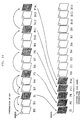
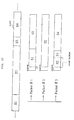
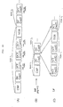
- a continuously inputted video signal is grouped into a GOP (Group of Pictures) which includes 15 frames.
- GOP Group of Pictures
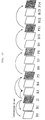
- the first two frames of a GOP are processed as B-pictures (B0, B1), and then the next frame is processed as an I-picture (I2).
- coding processing is performed such that P-pictures (P5, P8, P11, P14) may be produced with two B-pictures (B3, B4, B6, B7, B9, B10, B12, B13) interposed between each two adjacent ones of them.
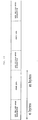
- the data coded in this manner are transmitted in the order of I2, B0, B1, P5, B3, B4, P8, B6, B7, P11, B9, B10, P14, B12 and B13 as seen in FIG. 58.
- This is because, since, for example, each of the B-pictures B0 and B1 (or B3 and B4) requires, as a predictive frame, another frame 12 (P5) which appears later in time, it cannot be decoded if the frame I2 (P5) is not prepared in advance.
- an I-picture involves a greater amount of data than P- and B-pictures and consequently data of I-pictures are read out, upon high speed reproduction, at a high frequency than upon ordinary reproduction. Consequently, there is a subject to be solved in that failure to read data of an I-picture sometimes occurs.
- a picture signal is first coded, for example, in accordance with the MPEG system, and then data only of an I-picture or of both of an I-picture and a P-picture or P-pictures are treated as data for high speed reproduction separately from data of the other P-pictures and B-pictures and are collectively recorded in units of, for example, a GOP and at the top of the GOP or a sector.
- the data for high speed reproduction may be all of I- and P-pictures or may be those of such I- and P-pictures which are comparatively high in priority degree. Consequently, the number of jumping operations can be reduced and such wasteful time as to wait for inputting of data to be decoded can be reduced.
- a picture signal recording method which comprises the steps of coding an input picture signal to produce a coded picture signal, dividing the coded picture signal into coded picture signals for high speed reproduction and the other coded picture signals, arranging the coded picture signals for high speed reproduction and the other coded picture signals so that the coded picture signals for high speed reproduction in a predetermined picture unit may be positioned at the top of the predetermined picture unit to produce a recording signal, and recording the recording signal onto a recording medium.
- a picture signal recording method which comprises the steps of coding an input picture signal to produce a coded picture signal, dividing the coded picture signal into coded picture signals for high speed reproduction and the other coded picture signals, successively arranging the coded picture signals for high speed reproduction and the other coded picture signals at a predetermined ratio to produce a recording signal, and recording the recording signal onto a recording medium.
- a picture signal recording method which comprises the steps of coding an input picture signal to produce a coded picture signal, dividing the coded picture signal based on one picture into coded picture signals of a high priority degree and coded picture signals of a low priority degree, producing a recording signal of such a packet construction that the coded picture signals of a high priority degree and the coded picture signals of a low priority degree are not present in one packet, and recording the recording signal onto a recording medium.
- a picture signal reproduction method which comprises the steps of reproducing, from a recording medium on which a coded picture signal is recorded such that coded picture signals for high speed reproduction and the other coded picture signals are disposed so that the coded picture signals for high speed reproduction in a predetermined picture unit are positioned at the top of the predetermined picture unit, only the coded picture signals for high speed reproduction, and decoding only the coded picture signals for high speed reproduction thus reproduced to produce a decoded picture for high speed reproduction.
- a picture signal reproduction method which comprises the steps of reproducing, from a recording medium on which a coded picture signal is recorded such that coded picture signals for high speed reproduction and the other coded picture signals are successively arranged at a predetermined ratio and the coded picture signal is allocated for each predetermined amount of codes to each sector, a sector to which the coded picture signals for high speed reproduction are allocated, separating, in response to a signal representative of a top address of the coded picture signals for high speed reproduction in a subcode of the sector, the coded picture signals for high speed reproduction and the other coded picture signals thus reproduced from the sector from each other, and decoding the thus separated coded picture signals for high speed reproduction to produce a decoded picture for high speed reproduction.
- a picture signal reproduction method which comprises the steps of reproducing, from a recording medium on which coded picture signals of a high priority degree and coded picture signals of a low priority degree, into which a coded picture signal based on one picture is divided, are recorded in such a packet construction that the coded picture signals of a high priority degree and the coded picture signals of a low priority degree do not exist in a same packet, the coded picture signal, separating the coded picture signals of a high priority degree and the coded picture signals of a low priority degree from each other in response to an identification signal provided in a header of the packet for identification between the coded picture signals of a high priority degree and the coded picture signals of a low priority degree, and decoding only the coded picture signals of a high priority degree upon high speed reproduction.
- a picture signal reproduction method which comprises the steps of reproducing, from a recording medium on which coded picture signals of a high priority degree and coded picture signals of a low priority degree, into which a coded picture signal based on one picture is divided, are recorded in such a packet construction that the coded picture signals of a high priority degree and the coded picture signals of a low priority degree do not exist in a same packet, the coded picture signal, separating the coded picture signals of a high priority degree and the coded picture signals of a low priority degree from each other in response to an identification signal provided in a header of the packet for identification between the coded picture signals of a high priority degree and the coded picture signals of a low priority degree, combining the coded picture signals of a high priority degree and the coded picture signals of a low priority degree in response to a link signal provided in the header of the packet to produce a combination signal, and decoding the combination signal to produce a decoded picture signal for ordinary reproduction
- a picture signal recording medium formed by the steps of coding an input picture signal to produce a coded picture signal, dividing the coded picture signal into coded picture signals for high speed reproduction and the other coded picture signals, arranging the coded picture signals for high speed reproduction and the other coded picture signals so that the coded picture signals for high speed reproduction in a predetermined picture unit may be positioned at the top of the predetermined picture unit to produce a recording signal, and recording the recording signal onto the recording medium.
- a picture signal recording medium formed by the steps of coding an input picture signal to produce a coded picture signal, dividing the coded picture signal into coded picture signals for high speed reproduction and the other coded picture signals, successively arranging the coded picture signals for high speed reproduction and the other coded picture signals at a predetermined ratio to produce a recording signal, and recording the recording signal onto a recording medium.
- a picture signal recording medium formed by the steps of coding an input picture signal to produce a coded picture signal, dividing the coded picture signal based on one picture into coded picture signals of a high priority degree and coded picture signals of a low priority degree, producing a recording signal of such a packet construction that the coded picture signals for high speed reproduction and the other coded picture signals are not present in one packet, and recording the recording signal onto a recording medium.
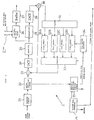
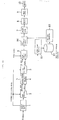
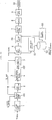
- FIG. 1 there is shown a picture signal coding apparatus or encoder to which the present invention is applied.
- a video signal to be transmitted is inputted to a picture signal coder 1, in which it is coded, for example, in accordance with the MPEG system.
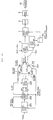
- the picture signal coder 1 may be constructed in such a manner as shown in FIG. 2.
- a video signal is inputted to a blocking circuit 21, in which the format thereof is converted from a standard format, for example, of the NTSC system into a block format which includes a macro block unit of, for example, 16 x 16 picture elements.
- the data converted into data of the block format are inputted to a motion prediction circuit 22 and then transmitted to a difference detector 23.
- picture data to which motion compensation has been performed are supplied from field memories 32A to 32D by way of a predictor 33.
- the difference detector 23 detects and outputs a difference between the two inputs thereto.
- the output of the difference detector 23 is sent to a DCT (discrete cosine transform) circuit 24 which performs DCT processing as orthogonal transformation.
- DCT coefficient data obtained by DCT processing by the DCT circuit 24 are sent to and quantized by a quantizer 25.
- the quantized data from the quantizer 25 are outputted as coded data to a data selector 2 (FIG. 1) by way of a variable length coder 26, which performs variable length coding processing such as, for example, so-called Huffman coding or run-length coding and a buffer 27.
- the variable length coder 26 also codes control information necessary for decoding such as a predictive mode, a motion vector and a picture type.
- a signal representative of an accumulated amount of data in the buffer 27 is fed back from the buffer 27 to the quantizer 25.
- the quantizer 25 determines a quantization step so that the accumulated data amount may not cause an overflow or an underflow of the buffer 27.
- the quantized data outputted from the quantizer 25 are inputted also to a dequantizer 38, by which dequantization processing complementary to the quantization processing by the quantizer 25 is performed.
- the output of the dequantizer 25 is processed by IDCT (inverse DCT) processing complementary to the DCT processing by the DCT circuit 24 by an IDCT circuit 29.
- IDCT inverse DCT
- the output of the IDCT circuit 24 is supplied to an adder 30.
- the adder 30 adds the output of the IDCT circuit 29 and data obtained by motion prediction of the outputs of the field memories 32A to 32D by the predictor 33.
- the output of the adder 30 is supplied to and stored into one of the field memories 32A to 32D by way of a selector 31.
- the motion prediction circuit 22 detects, in units of a macro block, an absolute difference sum of a motion vector between pictures (frames), a predictive picture corresponding to the motion vector and picture elements of an object picture for coding and detects a predictive error in intra-picture prediction which is a difference between an absolute value of the sum of picture elements of the object picture (frame) for coding and the sum of absolute values of the picture elements.
- the motion prediction circuit 22 outputs the thus detected data (the data of the motion vector between the pictures, the data of the absolute value difference sum and the predictive error in intra-picture prediction) to a predictive mode determination circuit 35.
- the motion predictive mode determination circuit 35 determines, for example, one of the following motion predictive modes in units of a macro block.
- a P-picture is basically predicted from a frame (I-picture or P-picture) preceding in time (in the past).
- a B-picture is basically predicted from a frame (I-picture and P-picture) preceding in time (in the past) and another frame (I-picture or P-picture) succeeding in time (in the future).
- a predictive mode is determined in such a manner as described above when the smaller one of X and Y is smaller than a predictive error by intra-picture prediction, but when the smaller one of X and Y is larger than a predictive error by intra-frame prediction, a B-picture is coded by intra-frame (intra-picture) coding.
- a read address generator 34 and the predictor 33 which is connected to the field memories 32A to 32D, predictive mode data and a motion vector from the predictive mode determination circuit 35 are supplied.
- the read address generation circuit 34 varies its read address in response to the data. Consequently, data for which motion compensation has been performed are outputted from the predictor 33.
- a picture type generator 36 generates a picture type signal PTYPE (identification signal indicating as which one of I-, P- and B-pictures the picture is to be processed) in response to a sequence of a picture type inputted thereto from an inputting section not shown, and outputs the picture type signal PTYPE to the predictive mode determination circuit 35, the data selector 2 and the buffer selector 5 (FIG. 1).
- PTYPE identification signal indicating as which one of I-, P- and B-pictures the picture is to be processed
- a picture signal outputted from the buffer 27 of the picture signal coder 1 in this manner is inputted to the data selector 2.
- the data selector 2 separates data for high speed reproduction from the other data.
- the data selector 2 supplies data of I-pictures and P-pictures in response to a picture type signal PTYPE from the picture type generation circuit 36 (FIG. 2) and supplies the data as data for high speed reproduction to a buffer 3. Further, the data selector 2 supplies data of B-pictures as the other data (data other than the data for high speed reproduction) to another buffer 4. Further, the data selector 2 generates an identification flag (data mode signal) S_FF, which has the value 1 for data for high speed reproduction but has the value 0 for any other data.
- a GOP is constituted from pictures of 15 frames B0 to P14 as shown in FIG. 57.
- the picture signal coder 1 performs coding in the order of the frames I1, B0, B1, P5, B3, B4, P8, B6, B7, P11, B9, B10, P14, B12 and B13 and outputs the data in this order.
- the data of the frames I2, P5, P8, P11 and P14 are written into the buffer 3 in response to the picture type signal PTYPE from the picture type generator 36 while the data of the frames B0, B1, B3, B4, B6, B7, B9, B10, B12 and B13 are written into the buffer 4.
- the buffer selector 5 After data of one GOP are written, the buffer selector 5 successively reads out the data for high speed reproduction written in the buffer 3 first and then reads out the other data written in the buffer 4, and outputs the data to a data multiplexer 6.
- the data multiplexer 6 multiplexes the picture data inputted thereto from the buffer selector 5 with audio data supplied thereto from a circuit not shown.
- the thus multiplexed signal is inputted to a sector allocator 7, by which allocation of the signal to sectors on a recording medium 10 such as a disk for each fixed amount of data is performed.
- the sector allocator 7 further codes and transmits a data mode signal S_FF indicative of whether or not the data are data for high speed reproduction.
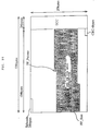
- each sector is constructed, for example, in such a manner as shown in FIG. 6.
- Each of sectors has a subcode (Subcode) of 28 bytes indicative of contents of the sector added to the top thereof.
- a sector mark (Sector Mark) is disposed at the top of the subcode, and a sector address (Sector Address) and a time code (Time Code) are disposed subsequently to the sector mark. Then, a data mode signal S_FF described above is disposed subsequently to the time code.
- ECC error detection and correction circuit
- data for high speed reproduction data of an I-picture and P-pictures
- data for high speed reproduction data of an I-picture and P-pictures
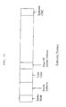
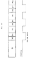
- data length of each GOP is not necessarily fixed, when data of a GOP are used up intermediately in a sector, dummy data are added to the sector as seen from FIG. 9. In this manner, data for high speed reproduction of each GOP are disposed at the top of the sector without fail.
- frames of a signal inputted to the picture signal coder 1 in the order of the frames B0 to P14 are recorded in the order of the frames I2, P5, P8, P11, P14 (frames for high speed reproduction), B0, B1, B3, B4, B6, B7, B9, B10, B12 and B13 (the other frames) as shown in FIG. 10.
- the data for high speed reproduction are recorded collectively in units of a GOP at the top of each sector.
- the recording medium 10 is, for example, an optical disk
- it is manufactured in such a manner as illustrated in FIG. 11.
- an original plate made of, for example, glass is prepared, and a recording material such as, for example, a photoresist is applied to the original plate. Consequently, a recording original plate is completed.
- bit stream (software) obtained by the processing by the picture signal coding apparatus of FIG. 1 described above is edited (pre-mastering) when necessary so that a signal of a format to be recorded onto an optical disk is produced. Then, a laser beam is modulated in response to the recording signal and irradiated upon the photoresist on the original plate to record the recording signal on the photoresist on the original plate.
- the original plate is developed so that pits are produced on the original plate.
- the original plate prepared in this manner is processed, for example, by electroforming to produce a metal original plate to which the pits on the glass original plate are transferred.
- a metal stamper is produced from the metal original plate and is used as a metal mold for molding.
- Such a material as PMMA (acrylic) or PC (polycarbonate) is injected, for example, by injection into the metal mold and then left to cure. Or else, a material such as 2P (resin which cures with ultraviolet rays) is applied to the metal stamper and then ultraviolet rays are irradiated upon the metal stamper to cause the material to cure. Consequently, the pits on the metal stamper can be transferred to the replica made of a resin.
- a material such as PMMA (acrylic) or PC (polycarbonate) is injected, for example, by injection into the metal mold and then left to cure.
- a material such as 2P (resin which cures with ultraviolet rays) is applied to the metal stamper and then ultraviolet rays are irradiated upon the metal stamper to cause the material to cure. Consequently, the pits on the metal stamper can be transferred to the replica made of a resin.
- a reflection film is formed by vapor deposition, sputtering or a like means on the replica produced in this manner. Or else, such reflection film may be formed by spin coating.
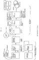
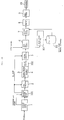
- a data reader 41 accesses to the recording medium 10 to reproduce data recorded on the recording medium 10 and outputs the data to a demodulator 42.
- the data reader 41 accesses to the recording medium 10 to reproduce data recorded on the recording medium 10 and outputs the data to a demodulator 42.
- the data reader 41 accesses to the recording medium 10 to reproduce data recorded on the recording medium 10 and outputs the data to a demodulator 42.
- the data reader 41 is a magnetic head, but when the recording medium 10 is an optical disk, the data reader 41 is an optical head.
- the demodulator 42 demodulates the data supplied thereto from the data reader 41.
- the thus decoded data are processed by detection and correction of an error by an error detection and correction circuit (ECC) 43 and are then inputted to a data demultiplexer 44.
- ECC error detection and correction circuit
- the data demultiplexer 44 demultiplexes the data into a video signal and an audio signal and outputs the audio signal to a circuit not shown.
- the data demultiplexer 44 further decodes the data mode signal S_FF in a subcode (FIG. 7) and outputs it to a data discriminator 45. Meanwhile, the video signal separated by the data demultiplexer 44 is inputted to the data discriminator 45.
- the data discriminator 45 distributes data supplied thereto from the data demultiplexer 44 in response to the data mode signal S_FF also supplied thereto from the data demultiplexer 44.
- the data mode signal S_FF is 1, since the picture data inputted then are data for high speed reproduction, the picture data are supplied to a buffer 46.
- the data mode signal S_FF is 0, since the picture data inputted then are data of the other kind, the picture data are supplied to another buffer 47.
- the data of the frames I2, P5, P8, P11 and P14 are stored into the buffer 46 while the data of the other frames B0, B1, B3, B4, B6, B7, B9, B10, B12 and B13 (other data) are stored into the other buffer 47 as seen from FIG. 14.
- a header is arranged at the top of the data of each frame, and the picture type of the frame and an ID representative of the frame number are arranged in the header.
- a buffer selector 48 reads the ID and discriminates to which one of the frames B0 to P14 of a GOP the data of the frame belong. Then, the buffer selector 48 reads, upon ordinary reproduction, data in the order of I2, B0, B1, P5, B3, B4, P8, B6, B7, P11, B9, B10, P14, B12 and B13 and outputs them to a picture signal decoder 49.
- the picture signal decoder 49 decodes the picture signal inputted thereto and re-arranges the data back into the order same as that when the picture signal was inputted to the picture signal coder 1, that is, into the order of B0, B1, I2, B3, B4, P5, B6, B7, P8, B9, B10, P11, B12, B13 and P14.
- the picture signal decoder 49 outputs the data in the thus re-arranged order.
- the picture signal decoder 49 is constructed, for example, in such a manner as shown in FIG. 15.
- a code bit stream input from the buffer selector 48 is temporarily stored into a buffer 61.
- the data are read out from the buffer 61 and decoded by inverse variable length coding (variable length decoding) by an inverse variable length coder (IVLC) 62.
- the thus decoded data are inputted to a dequantizer 63, by which they are dequantized for each block in accordance with information (a quantization step) extracted from the bit stream.
- the dequantized data from the dequantizer 63 are transformed by inverse DCT (IDCT) by an IDCT circuit 64.
- IDCT inverse DCT
- the dequantizer 63 and the IDCT circuit 64 operate complementarily to the quantizer 24 and the DCT circuit 24 of FIG. 2, respectively.
- a read address generator 70 varies the read address of one of field memories 68A to 68D in response to a predictive mode and a motion vector separated from the input data by the inverse variable length coder 62. Consequently, data are read out from the one of the field memories 68A to 68D and processed by motion compensation by a predictor 69, and the output of the predictor 69 is inputted to an adder 65.
- the adder 65 adds the output of the predictor 69 to the output of the IDCT circuit 64 to regenerate an original picture. The thus regenerated picture is stored as a next predictive picture into the field memories 68A to 68D.
- Picture signals stored at the address generated by a display address generator 72 are read out from the field memories 68A to 68D and supplied to a scan converter 67 by way of a selector 66.
- the scan converter 67 converts the number of lines of the data inputted thereto and outputs the resulted data to a display such as a CRT (cathode ray tube) not shown. A picture reproduced from the recording medium 10 is displayed in this manner.
- a period signal generator 71 generates a frame pulse signal as a period signal synchronized with an external period signal outputted, for example, from the display and outputs the frame pulse signal to the display address generator 72.
- the display address generator 72 generates a display address in synchronism with the frame pulse signal.
- the data reader 41 reads data for high speed reproduction from the top of the sector. After the reading is completed, the data reader 41 performs track jumping to a next sector in which data for high speed reproduction are recorded, and then waits rotation of the disk. When the top of the sector in which data for high speed reproduction are recorded comes to the data reader 41, the data reader 41 reads the data for high speed reproduction recorded at the top of the sector. The data for high speed reproduction thus read are decoded similarly as upon ordinary reproduction by the picture signal decoder 49. The sequence of operations described above is repeated to effect high speed reproduction.
- a picture signal coding apparatus (encoder) in the second embodiment of the present invention is constructed similarly to the picture signal coding apparatus of the first embodiment except the following points.
- the buffer selector 5 shown in FIG. 1 supervises the buffers 3 and 4 and reads out and outputs the outputs of the buffers 3 and 4 at the ratio of, for example, n:m to the data multiplexer 6. Consequently, data for high speed reproduction and the other data are written at the ratio of n:m onto the recording medium 10 as seen from FIG. 17.
- the sector allocator 7 adds a subcode in accordance with such a format as shown in FIG. 18.
- signals FF_Pointer and FF_Size are recorded in addition to the data mode signal S_FF as apparently seen from comparison with the subcode format in the first embodiment shown in FIG. 7.
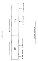
- the signal FF_Pointer represents a top address (entry pointer) of data for high speed reproduction in each sector as seen from FIG. 19.
- the signal FF_Size represents an amount of the range indicated by slanting lines in FIG. 19, that is, an amount of data for high speed reproduction.
- the head of data for high speed reproduction does not necessarily coincide with the head of a sector. Therefore, rapid reproduction of data for high speed reproduction is permitted by recording the top address of data for high speed reproduction in each sector into a Subcode and transmitting the same.
- a picture signal decoding apparatus (decoder) in the second embodiment is constructed similarly to the picture signal decoding apparatus of the first embodiment shown in FIG. 12 except the data discriminator 45.
- the picture signal decoding apparatus operates similarly to the picture signal decoding apparatus in the first embodiment except that described above.
- a picture signal coding apparatus in the third embodiment is constructed similarly to the picture signal coding apparatus in the second embodiment except the sector allocator 7.
- a top address (Next Sector Address) of a sector in which next data for high speed reproduction are recorded is recorded together with the signals FF_Pointer and FF_Size into a subcode as shown in FIG. 20 by the sector allocator 7.
- a picture signal decoding apparatus in the third embodiment reads and stores, when a predetermined sector including data for high speed reproduction is to be read in in order to perform high speed reproduction, an address of a sector which includes next data for high speed reproduction in advance. Then, when reading of the data for high speed reproduction of the sector is completed, the data reader 41 is moved in response to the address thus stored and waits rotation of the disk to effect reproduction of the next data for high speed reproduction.
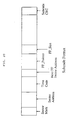
- the fourth embodiment is constructed similarly to the second embodiment except that an address of a recording position (entry point) of data for high speed reproduction is written in the TOC (Table of Contents) of the recording medium 10.
- addresses of sectors of data for high speed reproduction of the recording medium 10 are written in advance in the TOC as seen in FIG. 21 (N entry points are written in the example shown in FIG. 21).
- a TOC addition circuit 84 is interposed between the data multiplexer 6 and the sector allocator 7. Further, an entry point detector 81 for detecting an entry point from the output of the data multiplexer 6 is provided, and an entry point detected by the entry point detector 81 is supplied to and stored into an entry point storage apparatus 81.
- a TOC data generator 83 generates TOC data corresponding to entry points stored in the entry point storage apparatus 82 and outputs the TOC data to the TOC addition circuit 84.
- the TOC data are arranged in form as a TOC and inputted to the TOC addition circuit 84, by which the TOC data are added to the top of multiplexed data.
- the TOC data including the entry points are recorded onto the innermost circumferential track of the recording medium 10.
- FIG. 23 shows an example of construction of a picture signal decoding apparatus in the fourth embodiment.
- Information of the TOC recorded on the innermost circumferential track of the recording medium 10 is demultiplexed by the demultiplexer 44 and stored into a TOC storage apparatus 85.
- the data reader 41 reads the TOC information stored in the TOC storage apparatus 85, calculates an address of next data for high speed reproduction and moves to the position of the address. Then, the data reader 41 reads out the data for high speed reproduction to regenerate an original picture signal. The sequence of operations described so far is repeated.
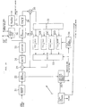
- FIG. 24 An example of construction of a picture signal coding apparatus (encoder) according to the fifth embodiment of the present invention is shown in FIG. 24.
- a priority degree adder 101 is connected between the picture signal coder 1 and the data selector 2.
- a priority degree signal S_HP outputted from the priority degree adder 101 is supplied to the data selector 2 and the buffer selector 5 in place of the picture type signal PTYPE from the picture signal coder 1 shown in FIG. 22.
- the TOC data generator 83 and the TOC addition circuit 84 shown in FIG. 22 are omitted, and the output of the entry pint storage apparatus 82 is supplied directly to the sector allocator 7.
- a data formatter 102 is interposed between the buffers 3 and 4 and the buffer selector 5.
- the other construction of the picture signal coding apparatus is similar to that of the picture signal coding apparatus shown in FIG. 22.
- the picture signal coder 1 is constructed in such a manner as shown, for example, in FIG. 25.
- the basic construction of the picture signal coder 1 is substantially similar to that of the picture signal coding apparatus shown in FIG. 2 except that the buffer 27 outputs a generated bit amount signal corresponding to the amount of bits generated therefrom to the priority degree adder 101.
- the priority degree adder 101 is constructed in such a manner as shown, for example, in FIG. 26.
- data supplied from the picture signal coder 1 are inputted to a high priority data amount allocator 111.
- the priority data amount allocator 111 applies priority order numbers to the data inputted thereto.
- Data of I- and P-pictures are provided with such priority order numbers as shown in FIG. 27.
- priority order numbers are applied in the order of the frame headers (Frame Headers), the slice headers (Slide Headers), the address (Address), type (Type) and quantization (Quant) of the macro block (MB), the DC coefficient for DCT, the low frequency coefficient for DCT and the high frequency coefficient for DCT.
- the frame headers (Frame Headers), the slice headers (Slide Headers), the address (Address), type (Type) and quantization (Quant) of the macro block (MB) and the DC coefficient for DCT are essential data and cannot be omitted.
- priority order numbers are applied in the order of the frame headers (Frame Headers), the slice headers (Slide Headers), the address (Address), type (Type) and quantization (Quant) of the macro block (MB), the motion vectors (Motion Vectors), the DC coefficient for DCT, the low frequency coefficient for DCT and the high frequency coefficient for DCT.
- the frame headers (Frame Headers), the slice headers (Slide Headers), the address (Address), type (Type) and quantization (Quant) of the macro block (MB), the motion vectors (Motion Vectors) and the DCT coefficient for DCT are essential and cannot be omitted.
- the essential data of an I-picture and a P-picture are data absolutely necessary for decoding and cannot be omitted, they are always decoded, but since the other data, that is, the low frequency coefficient for DCT and the high frequency coefficient for DCT have a comparatively low degree of priority (they are necessary to enhance the picture quality), they can be omitted from decoding when necessary.
- Data of a B-picture are regarded as data having a low degree of priority, and decoding of them can be omitted.
- the data amount allocator 111 outputs data in the order of the degree of priority to a data separator 112 and an imaginary buffer 113.
- the data amount allocator 111 sets a buffer size (storage capacity) of the imaginary buffer 113 in response to a generated bit amount generated from the buffer 27 of the picture signal decoder 1 and stored amounts of data in the buffers 3 and 4. Data outputted from the data amount allocator 111 are successively inputted to and stored into the imaginary buffer 113 in the descending order of the degree of priority. Then, when the stored data amount of the imaginary buffer 113 reaches the storage capacity thus set as a buffer size, the imaginary buffer 113 outputs a data separation signal to the data separator 112.
- the data separator 112 outputs data inputted thereto in accordance with the order of priority from the data amount allocator 111 as data having a high degree of priority to the data selector 2 for a period until after a data separation signal is inputted from the imaginary buffer 113 to the data separator 112. Further, after a data separation signal is inputted from the imaginary buffer 113, the data separator 112 outputs data inputted thereto from the data amount allocator 111 as data having a low degree of priority to the data selector 2.
- the priority degree allocation is performed in units of one slice.
- a data separation point (a separation point between data of a high priority degree and data of a low priority degree) is determined for each one slice.
- FIG. 28 A concrete example of the procedure of the priority degree allocation is illustrated in FIG. 28.
- a region of a size equal to a storage capacity (buffer size) determined by the high priority data amount allocator 11 is assured on the imaginary buffer 113.
- the data amount allocator 111 inputs data to the imaginary buffer 113 in accordance with the priority order illustrated in FIG. 27.
- FIG. 28 illustrates a manner wherein the frame headers, the macro block headers, the block headers, the motion vectors, the DC coefficient for DCT, the low frequency coefficient for DCT and the high frequency coefficient for DCT are successively written into the imaginary buffer 113 so that the amount of data stored in the imaginary buffer 113 increases gradually.
- the amount of data inputted to the imaginary buffer 113 is supervised, and those data inputted before a maximum amount of data which does not exceed the capacity set for the imaginary buffer 113 is inputted to the imaginary buffer 113 are determined as data of a high priority degree. Data after then are determined as data of a low priority degree. The point at which a data separation signal makes a data separation point.
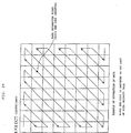
- FIG. 29 illustrates an example of separation of DCT coefficients at a separation point into data of a high priority degree and data of a low priority degree.
- DCT coefficients of a block including 8 x 8 picture elements are scanned by zigzag scanning as seen from FIG. 29 and thus inputted in this order to the imaginary buffer 113.
- a data separation signal is outputted to the data separator 112.
- the data separator 112 adds a block end code (EOB: End of Block) to the last end of each block of data of a high priority degree. Consequently, the end position of each block can be discriminated only from data of a high priority degree.
- EOB End of Block
- a bit stream including only data of a high priority degree satisfies the syntax of the main profile level and the main level of the MPEG2, and accordingly, it can be decoded similarly to a bit stream which includes data of all of the kinds.
- the data separator 112 further transfers, together with data of a high priority degree or data of a low priority degree, a priority degree signal S_HP for identification of whether the data are data of a high priority degree or data of a low priority degree.
- the priority degree signal S_HP is 1 for data of a high priority degree but 0 for data of a low priority degree.
- the data formatter 102 adds a header of a packet to data of a high priority degree and a low priority degree.
- Data of a high priority degree and data of a low priority degree are combined into a single packet in units of a packet so that the data of two kinds may not be mixed with each other.
- Data for one sector are constituted from a plurality of packs, and each pack is constituted from a plurality of packets.
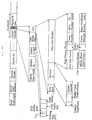
- FIG. 31 indicates a format of a pack. As shown in FIG. 31, a pack start code (Pack Start Code), a system clock reference (System Clock Reference) and a system header (System Header) are added to the top of the pack, and packets are arranged subsequently to them.
- Pack Start Code Pack Start Code
- System Clock Reference System Clock Reference
- System Header system header
- a packet header (Packet Header) is disposed at the top of each packet, and a packet start code (Packet Start Code), a stream ID (Stream ID), a packet length (Packet Length), other necessary header information (Other Header Data) and an adaptation header (AH: Adaptation Header) are disposed in the packet header.
- Packet Start Code Packet Start Code
- Stream ID stream ID
- Packet Length Packet Length
- AH Adaptation Header
- the other necessary header information Includes a stuffing byte (Stuffing byte), a reservation code "01", a buffer scale (STD buffer scale), a buffer size (STD buffer scale) and a time stamp (Time stamp) arranged therein.
- a synchronization byte (Sync Byte)
- a service ID (Service ID)
- a data link header (Data Link Header)
- a priority flag (Priority) corresponding to the priority degree signal S_HP is recorded in the service ID.
- the priority degree signal S_HP is equal to 1
- S_HP 0, also the flag is set to 0 (low).
- the packet type Packet Type
- a flag for identification between data recorded in the packet are a video signal or an audio signal is recorded.
- the packet counter Packet Counter
- a consecutive number corresponding to the packet is recorded so that the continuity of packets can be checked. It is to be noted that different count values obtained by counting data of a high priority degree and data of a low priority degree independently of each other are recorded in the packet counter.
- a slice is data constituted from data of, for example, 16 lines of a picture of one frame.
- FIG. 32 schematically illustrates a function of a start pointer of a high priority degree or a low priority degree.
- data of slices S1, S2, S3, S4, ... are successively allocated to packets 1, 2, 3, ..., in the top header of each packet, the address of the first slice whose header is included in the packet (for example, the top address of a slice S1 for the packet 1, and the top address of a slice S3 for the packet 3) is recorded as a start pointer.
- Data of a high priority degree or data of a low priority degree to which a packet header has been added in this manner are outputted to the data multiplexer 6 by way of the buffer selector 5 (FIG. 24).
- the buffer selector 5 supervises the buffers 3 and 4 and a sector allocated by the sector allocator 7 and outputs the outputs of the buffers 3 and 4 at the ratio of, for example, n:m to the data multiplexer 6. Consequently, data of a high priority degree (data for high speed reproduction) and data of a low priority degree (the other data) are written at the ratio of n:m onto the recording medium 10.
- the data multiplexer 6 multiplexes picture data and audio data.
- a sector on the recording medium 10 is allocated by the sector allocator 7.
- the sector allocator 7 further transmits, when the sector includes data for high speed reproduction, an address of a sector which includes next data for high speed reproduction.
- Each sector is constructed in such a manner as illustrated in FIG. 19 similarly to that described hereinabove.
- a Subcode of 28 bytes indicative of contents of the sector is added to the top of each sector.
- the format of the Subcode in the present embodiment is such as illustrated in FIG. 33.
- a top address Next FF Sector Address (entry point) of a sector in which next data for high speed reproduction are recorded is recorded in the Subcode of the sector in which data for high speed reproduction are recorded.
- the top address Next FF Sector Address of a sector in which next data for high speed reproduction are recorded is read simultaneously as seen from FIG. 34, and when reproduction of the preceding data for high speed reproduction is completed, the data reader can immediately jump to the sector in which the next data for high speed reproduction are recorded.
- the entry point detector 81 detects an address (entry point address), in which the Next FF Sector Address is recorded, from the output of the data multiplexer 6.
- the entry point address is stored into the entry point storage apparatus 82.
- the sector allocator 7 writes the entry point stored in the entry point storage apparatus 81 into the Subcode.
- FIG. 36 An example of construction of a picture signal decoding apparatus (decoder) in the fifth embodiment is shown in FIG. 36.
- entry point data are separated by the data demultiplexer 44 and supplied to and stored into the entry point storage apparatus 121. Then, the data reader 41 is controlled in response to the storage value to vary the accessing position thereof.
- a data deformatter 122 is interposed between the data demultiplexer 44 and the data discriminator 45, and a priority degree decoder 123 is interposed between the buffer selector 48 and the picture signal decoder 49.
- the data deformatter 122 separates the priority degree signal S_HP (Priority) and the data link header (FIG. 31) from the Subcode of data inputted thereto and supplies them to the data discriminator 45 and the priority degree decoder 123.
- S_HP Principal priority
- FIG. 31 data link header
- the data demultiplexer 44 separates picture data and audio data from each other and decodes and supplies and stores an entry point to and into the entry point storage apparatus 121.
- the picture data are inputted to the data deformatter 122, by which data are extracted from each packet.
- the data demultiplexer 44 reads, from the priority degree flag Priority of the packet header, whether or not data in the packet are data of a high priority degree (whether or not the priority degree flag S_HP is equal to 1) and outputs a result of the reading to the data discriminator 45.
- the data discriminator 45 discriminates, from the priority degree flag S_HP inputted thereto from the data deformatter 122, whether or not the input data are data for high speed reproduction (data of a high priority degree).
- the priority degree decoder 123 is constituted, as shown, for example, in FIG. 38, from a buffer 131 and a multiplexer (MUX) 132.
- MUX multiplexer
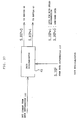
- high priority data I2H, P5H, P8H, P11H and P14H illustrated in FIG. 35 are supplied from the buffer 46 by way of the buffer selector 48 to and stored into the buffer 131.
- the multiplexer 132 since the priority degree flag S_HP is inputted from the data deformatter 122, the multiplexer 132 reads out the data and outputs them as they are to the picture signal decoder 49.
- the entry pointer recorded in the subcode of the sector is read and stored into the entry point storage apparatus 121.
- the data reader 41 performs track jumping to the entry point indicated by the thus stored entry pointer.
- high priority data I2H, P5H, P8H, P11H and P14H stored in the buffer 46 and low priority data I2L, B0, B1, P5L, B3, B4, P8L, B6, B7, P11L, B9, B10, P14L, B12 and B13 stored in the buffer 47 are supplied by way of the buffer selector 48 to and stored into the buffer 131 of the priority degree decoder 123.
- the multiplexer 132 combines data of a high priority degree and data of a low priority degree in response to the data link header (FIG. 31) in the packet header supplied thereto from the data deformatter 122 to reconstruct the original decoded picture signal.
- the data I2H, P5H, P8H, P11H and P14H and the data 12L, P5L, P8L, P11L and P14L are combined to produce data I2, P5, P8, P11 and P14.
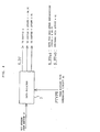
- FIG. 39 illustrates a method of restoring the original data in this manner.
- a start code (Sync Byte in FIG. 31) of a GOP is found out.
- a start code for data of a high priority degree is found out (the Service id whose Priority in FIG. 31 is 1 is sought).
- a start code for data of a low priority degree is found out (the Service id whose Priority in FIG. 31 is 0 is sought).
- the Frame Number and the Slice number found out at steps S12 and S13, respectively, are compared with each other.
- step S15 the data found out at steps S12 and S13 are combined. It is to be noted that, in this instance, the block end code provided at the last end of each block of the data of a high priority degree is removed.
- the multiplexer 132 changes the order of the pictures of the GOP to I2, B0, B1, P5, B3, B4, P8, B6, B7, P11, B9, B10, P14, B12 and B13 and outputs the resulted data to the picture signal decoder 49.
- the sixth embodiment is similar to the fifth embodiment described hereinabove except that addresses of sectors which include data of a high priority degree for high speed reproduction are written in the TOC (Table of Contents).
- the construction of the TOC is similar to that illustrated in FIG. 21 described hereinabove.
- FIG. 40 An example of construction of a picture signal coding apparatus (encoder) in the present embodiment is shown in FIG. 40.
- a TOC addition circuit 84 is interposed between the data multiplexer 6 and the sector allocator 7 shown in FIG. 24.
- the entry point detector 81 detects an entry point from the output of the data multiplexer 6 and stores it into the entry point storage apparatus 82.
- the TOC data generation circuit 83 generates TOC data corresponding to data in the entry point storage apparatus 82 and outputs the TOC data to the TOC addition circuit 84.
- the TOC addition circuit 84 multiplexes the TOC data with picture data outputted from the data multiplexer 6.
- Operation of the TOC addition circuit 84 is basically similar to that in the embodiment shown in FIG. 22, and accordingly, overlapping description thereof is omitted herein to avoid redundancy.
- FIG. 41 An example of construction of a picture signal decoding apparatus (decoder) in the sixth embodiment is shown in FIG. 41.
- a TOC storage apparatus 85 is connected to the data demultiplexer 44 in place of the entry point storage apparatus 121 shown in FIG. 36.
- TOC data separated by the data demultiplexer 44 are stored into the TOC storage apparatus 85, and the accessing position of the data reader 41 is controlled in response to the stored data in the TOC storage apparatus 85.
- Operation of the picture signal decoding apparatus is basically similar to that in the embodiment of FIG. 23, and accordingly, overlapping description of it is omitted herein to avoid redundancy.
- the seventh embodiment is similar to the fifth embodiment except for the buffer selector 5 and the sector allocator 7 (FIG. 24).
- the buffer selector 5 in the seventh embodiment performs separation between data of a high priority degree for high speed reproduction and data of a low priority degree in units of a GOP.
- the sector allocator 7 in the seventh embodiment performs allocation of sectors so that the head of each GOP and the head of a corresponding sector may coincide with each other. Further, data of a high priority degree for high speed reproduction in units of a GOP are allocated to the head of the sector.
- the arrangement of the data recorded on the recording medium 10 in such a manner as described above is such as shown in FIG. 35. As seen from FIG.
- the eighth embodiment is similar to the fifth embodiment except for the buffer selector 5 and the sector allocator 7.
- the buffer selector 5 in the eighth embodiment performs separation of data of a high priority degree for high speed reproduction and data of a low priority degree in units of a frame. Data for high speed reproduction are allocated in units of a frame to the top of the frame.
- the ninth embodiment is similar to the fifth embodiment except for the priority degree adder 101 (FIG. 24).
- the priority degree adder 101 in the ninth embodiment determines an intra-macro block in each frame as data of a high priority degree and determines any other data as data of a low priority degree.
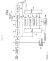
- FIG. 42 The construction of a picture signal encoding apparatus (encoder) in the tenth embodiment is shown in FIG. 42. It is to be noted that like elements to those of FIG. 24 are denoted by like reference numerals.
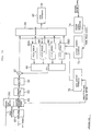
- a picture signal coder 201 is constructed in such a manner as shown in FIG. 43.
- the picture signal coder 201 is constructed in a similar manner to the picture signal coder 1 described hereinabove in connection with the fifth embodiment with reference to FIG. 25 except that the buffer 27 is omitted and the generated bit amount outputted from the buffer 27 in FIG. 25 is outputted from the variable length coder 26.
- the picture signal coder 201 codes a picture signal in a similar manner as described hereinabove with reference to FIG. 25 and outputs the coded data together with a code amount of the coded data (a generated bit amount).
- a signal (Buffer status B_FULL) representative of an accumulated amount (HP + LP) of high priority data HP and low priority data LP in a two-point buffer 204 which will be hereinafter described, is supplied in place of a generated bit amount so that the quantization step (dequantization step) of the quantizer (25 (dequantizer 28) is controlled so as not to cause an overflow or an underflow.
- the two-point buffer 204 serves also as the buffer 27 of the picture signal coding apparatus shown in FIG. 25.
- Coded data and a generated bit amount of the coded data outputted from the picture signal coder 201 are inputted to a priority degree adder 202. It is to be noted that the coded data are inputted in the descending order of the degree of priority to the priority degree adder 202 as described hereinabove with reference to FIG. 27.
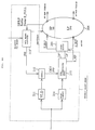
- the priority degree adder 202 is constructed, for example, in such a manner as shown in FIG. 44. Referring to FIG. 44, the priority degree adder 202 is supplied with, in addition to coded data and a generated bit amount of the coded data from the picture signal coder 201, a signal (Buffer status B_FULL) representative of a total accumulated amount of high priority data HP and low priority data LP of the two-point buffer 204.
- a signal Buffer status B_FULL
- Coded data are inputted to a syntax analysis (VLD) circuit 211 and a delay circuit 214.
- the VLD circuit 211 analyzes the coded data by syntax analysis and outputs a result of the analysis to a counter 212.
- the VLD circuit 211 processes the coded data by inverse variable length coding to detect an event (VLC event) of variable length coding processing, which has been performed for the coded data by the variable length coder 26 (FIG. 43) of the picture signal coding apparatus 201.
- variable length coder 26 performs coding with a set (run and level) of a number (run) of data which successively precede to certain non-zero data in a data train inputted thereto and a value (level) of the non-zero data. Such set (run and level) is called VLC event.
- the VLD circuit 211 outputs a detection signal to the counter 212 each time a VLC event is detected from coded data.
- coded data inputted to the delay circuit 214 are delayed by a time corresponding to the time of processing by the VLD circuit 211 and then outputted to a data separation/pbp adder 215.
- a generated bit amount of coded data and a signal (Buffer status B_FULL) representative of an accumulated amount of the two-point buffer 204 are inputted to a data allocator 213.
- the data allocator 213 determines the number of VLC events corresponding to an amount of data which can be allocated to high priority data in response to the generated bit amount of the coded data and the signal (Buffer status B_FULL) representative of the accumulated amount of the two-point buffer 204.
- the data allocator 213 determines the number of VLC events to a separation point at which DCT coefficients (AC coefficients) are separated into data of a high priority degree and data of a low priority degree.
- the number of VLC events determined by the data allocator 213 will be hereinafter referred to as pbp (priority break point). It is to be noted that the pbp and a data_partition_flag and a priority class, which will be hereinafter described, are described in AVC-491b version 2, Test Model 5, ISO/IEC JTCl/SC29/WGll, pp.110-116, April, 1993.
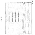
- the pbp is influenced principally by the generated bit amount of coded data from between the the generated bit amount of coded data and the accumulated amount (Buffer status B_FULL) of the two-point buffer 204.
- the generated bit amount of coded data is great, the pbp has a low value since the amount of data which can be allocated to high priority data is great, but on the contrary where the generated bit amount is small, the pbp has a high value since the amount of data which can be allocated to high priority data is great.
- the pbp has a low value, but on the contrary where the accumulated amount is small, the pbp has a high value.
- the pbp is described in (added to) the header of an MB (macro block) of coded data outputted from the delay circuit 214 by the data separation/pbp adder 215 which will be hereinafter described.
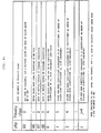
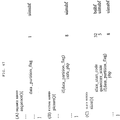
- coded data are numbered, in priority class (Priority class), 0, 1, 2, ... in the descending order of the priority degree as seen in FIG. 45, and data having the priority class of up to 4, that is, all data of a sequence, a GOP and a picture layer, data from the top of a slice layer to the pbp described in the MB header, data of the MB from the MB (macro block) stuffing (MB stuffing) to the MB type (MB type), data of motion vectors of the forward prediction, data of motion vectors of the rearward prediction and data of the MB from the CBP (Coded Block Pattern) to the DC coefficient of DCT coefficient (coefficient of the (0, 0)th component) are determined as essential data and hence as high priority data.
- priority class Priority class
- data having the priority class of up to 4 that is, all data of a sequence, a GOP and a picture layer, data from the top of a slice layer to the pbp described in the MB header, data of the MB from the
- coded data having the priority classes equal to or higher than 5, that is, data of a lower priority degree are determined as coefficients (AC coefficients) of a higher order except the DC coefficient of DCT coefficients.
- the pbp is the number of VLC events involved up to a separation point at which DCT coefficients (AC coefficients) are separated into data of a high priority degree and data of a low priority degree as described hereinabove, it is equal to the number of non-zero coefficients (AC coefficients) succeeding to the DC coefficient (coefficient of the (0, 0)th component) of the DCT coefficients in the order of zigzag scanning of the DCT coefficients.
- the priority class is represented as j + 4.
- the number of DCT coefficients (AC coefficients) of a block of 8 x 8 picture elements except the DC coefficient is 63, and accordingly, the number of non-zero Ac coefficients is 63 at the greatest. Therefore, the variable j ranges from 1 to 63 both inclusive.
- the pbp outputted from the data allocator 213 assumes a value ranging from 0 to 63.
- the pbp is determined for each slice by the data allocator 213 at a timing at which, for example, the top of the slice is inputted to the priority degree adder 202, and is outputted to the counter 212. Accordingly, the values of the pbp of blocks constituting a certain slice all have an equal value.
- the data allocator 213 determines a size of a region of the two-point buffer 204 into which high priority data HP are to be stored, and outputs a signal "partition" representative of the size to the two-point buffer 204.
- the two-point buffer 204 assures a region n into which high priority data HO are to be stored. It is to be noted that the remaining region is determined as a region into which low priority data LP are to be stored.
- the pbp determined by the data allocator 213 is outputted to the counter 212.
- the counter 212 is reset to zero at a timing at which the block end coder (EOB) is inputted to the VLD circuit 211, and counts the detection signal outputted from the VLD circuit 211 and indicating that a VLC event is detected from coded data. Then, when the count value becomes equal to the pbp from the data allocator 213, the counter 212 outputs a division signal DEV and the pbp from the data allocator 213 to the data separation/pbp adder 215.
- EOB block end coder
- the data separation/pbp adder 215 outputs coded data, which have been inputted in the descending order of priority to and delayed by the delay circuit 214, as high priority data to the data formatter 203 and outputs a priority degree signal S_HP of 1 to the data formatter 203.
- the data separation/pbp adder 215 outputs coded data inputted thereto after then as low priority data LP to the data formatter 203 and outputs the priority degree signal S_HP of 0 to the data formatter 203. Thereafter, when a block end code (EOB) is outputted from the delay circuit 214, the data separation/pbp adder 215 outputs coded data inputted thereto after then as high priority data again to the data formatter 203 and outputs the priority degree signal S_HP of 1 to the data formatter 203.
- EOB block end code
- the data separation/pbp adder 215 outputs all of the data of the block as high priority data HP to the data formatter 203. Further, in this instance, the counter 212 is reset.
- FIG. 46 A concrete example of the priority allocation is illustrated in FIG. 46.
- the DC coefficient (DC Coeff) of a block Y1 the AC coefficients of the block Y1 (DCT Coeff1, DCT Coeff2 and DCT Coeff3)
- a block end coder (EOB) the DC coefficient (DC Coeff) of another block Y2
- the AC coefficients (DCT Coeff1, ..) of the block Y2 ...
- the CBP as essential data is first determined as high priority data HP ((B) of FIG. 46).
- DC coefficient (DC Coeff) of the block Y1 succeeding to the CBP is essential data, it is determined as high priority data HP ((B) in FIG. 46)).
- the data separation point is at the position of the DC coefficient, and accordingly, the AC coefficients of the block Y1 (DCT Coeff1, DCT Coeff2 and DCT Coeff3) succeeding to the DC coefficient (DC Coeff) of the block Y1 are all determined as low priority data LP ((C) in FIG. 46).
- a pbp outputted from the counter 212 is written together with other necessary information into such a sequence header, a picture header or a slice header corresponding to high priority data or low priority data as illustrated in FIG. 47.
- a flag data_partition_flag indicating whether or not priority degree allocation should be performed that is, whether or not coded data should be separated into high priority data and low priority data, is described. It is to be noted that the flag data_partition_flag is set only when priority degree allocation should be performed.
- essential data allocated to high priority data without fail as described above by the priority degree adder 202 are only I- and P-pictures. Accordingly, the priority degree adder 202 allocates other data of the I- and P-pictures (data other than the essential data described above) and data of B-pictures as one of high priority data and low priority data in response to the pbp.
- the data formatter 203 adds a header of a packet illustrated in FIG. 48 which will be hereinafter described to high priority data or low priority data outputted from the priority degree adder 202. Further, the high priority data and the low priority data are gathered together in units of a packet so that the data of the two kinds may not be present in a mixed condition with each other in the one packet.
- the packet of the high priority data and the low priority data is stored into the two-point buffer 204, which is divided at n:m into two regions in such a manner as described hereinabove, and then read out at the ratio of n:m from the two-point buffer 204 to the buffer selector 205. It is to be noted that, in this instance, the high priority data and the other data (low priority data) are successively read out in this order from the two-point buffer 204 and outputted to the buffer selector 205.
- the buffer selector 205 converts the packets of the high priority data and the low priority data thus read out into a pack.
- FIG. 48 shows a format of a pack outputted from the buffer selector 205.
- the pack shown has the same structure as the format of the pack described hereinabove with reference to FIG. 31 except for the data link header (Data Link Header) which constitutes the adaptation header AH of the packet header.
- Data Link Header Data Link Header
- a slice number of high priority data is described into the link header, and consequently, data which can be decoded completely can be obtained in units of a slice similarly as to the fifth embodiment.
- data which can be decoded completely can be obtained in units of an MB (macro block).
- the packets of the high priority data and the low priority data packed in such a manner as described above are outputted to the data multiplexer 6. Then, similarly as in the case described hereinabove with reference to FIG. 24, the data of a high priority degree (data for high speed reproduction) and the data of a low priority degree (data of the other type) are written onto the recording medium 10.
- the two-point buffer 204 is formed as a ring buffer such that the storage region thereof is divided into two regions including an area n, into which high priority data HP are to be stored, and another area m, into which low priority data LP are to be stored, as indicated by a broken line in FIGS. 42 and 44 in response to a signal "partition" (FIG. 44) supplied thereto from the data allocator 213 of the priority degree adder 202 as described hereinabove.
- reading or writing of data from or into the region n is controlled by an HP read pointer or an HP write pointer while reading or writing of data from or into the region m is controlled by an LP read pointer or an LP write pointer.
- the packet of the high priority data from the data formatter 203 is written into an address designated by the HP write pointer. Then, the packet of the high priority data is read out from an address designated by the HP read pointer and is outputted to the buffer selector 205. Meanwhile, the packet of the low priority data from the data formatter 203 is written into an address designated by the LP write pointer. Then, the packet of the low priority data is read out from an address designated by the LP read pointer and is outputted to the buffer selector 205.
- the decoder when a decoder for decoding a bit stream recorded on the recording medium 10 is considered, the decoder has a so-called code buffer which temporarily stores the bit stream transmitted thereto.
- an imaginary buffer having an equal capacity to that of the code buffer on the decoder side so that the code buffer may not overflow or underflow is assumed, and a bit stream produced as a result of coding is temporarily stored into and then outputted from the imaginary buffer and the amount of data accumulated in the imaginary buffer is supervised to effect control of the amount of codes to be generated (bit allocation for quantization).
- the accumulated data amount when a bit stream is outputted from the imaginary buffer for a period of time after the bit stream is inputted to the imaginary buffer until it is outputted is described into vbv_delay of a picture header, and on the decoder side, when the accumulated data amount of the code buffer becomes equal to the data amount indicated by the vbv_delay described in the picture header, a bit stream corresponding to the pictures is read out from the code buffer.
- the two buffers 3 and 4 for storing high priority data and low priority data, respectively are provided. Consequently, also the picture signal decoding apparatus (FIG. 36) for decoding a bit stream outputted from such picture signal coding apparatus requires the two buffers 46 and 47 for storing high priority data and low priority data, respectively.
- the two-point buffer 204 constructed as a ring buffer is divided into the two regions n and m for storing high priority data and low priority data, respectively, so that only description of one vbv_delay may be required.
- Reading and writing of data from and into the two-point buffer 204 is controlled with the HP read pointer, the HP write pointer, the LP read pointer and the LP write pointer as described above, and in this instance, if it is assumed that each pointer moves in the counterclockwise direction on the ring buffer as the two-point buffer 204, then the pointers are controlled so that the LP read pointer may not pass the LP write pointer, the HP write pointer may not pass the LP read pointer, the HP read pointer may not pass the LP write pointer, and the LP write pointer may not pass the HP read pointer.
- high priority data are stored within the range from the HP read pointer to the HP write pointer in the counterclockwise direction, and the magnitude of the range is controlled so that it may not exceed the magnitude of the region n when the two-point buffer 204 is divided at the ratio of n:m into two regions as described hereinabove.
- low priority data are stored within the range from the LP read pointer to the LP write pointer in the clock wise direction, and the magnitude of the range is controlled so that it may not exceed the magnitude of the region m when the two-point buffer 204 is divided at the ratio of n:m into two regions as described hereinabove.
- the capacity of such buffer as described above is defined to be 1.75 Mbits, and also the two-point buffer 204 is formed so that it has an equal storage capacity.
- FIG. 50 The construction of a picture signal decoding apparatus (decoder) in the tenth embodiment is shown in FIG. 50. It is to be noted that, in FIG. 50, like elements to those of FIG. 36 are denoted by like reference numerals.
- a bit stream recorded on the recording medium 10 is inputted, similarly as in the picture signal decoding apparatus shown in FIG. 36, by way of a data reading apparatus 41, a demodulation circuit 42 and an ECC circuit 43 to a data demultiplexer 44, by which it is demultiplexed into a video signal and an audio signal, which is outputted to a circuit not shown.
- the data demultiplexer 44 further decodes a data mode signal S_FF in a Subcode and outputs it to a data discriminator 221. Further, the video signal separated by the data demultiplexer 44 is inputted to the data discriminator 221.
- the data discriminator 221 distributes, in response to the data mode signal S_FF supplied thereto from the data demultiplexer 44, the data supplied thereto also from the data demultiplexer 44.
- the data discriminator 221 discriminates data (packet) supplied thereto then as high priority data and supplies them to the two-point buffer 222.
- the data discriminator 221 discriminates picture data (packet) inputted thereto then as low priority data (packet) and supplies them to a two-point buffer 222.
- the two-point buffer 222 is constructed in a similar manner to that of the two-point buffer 204 shown in FIG. 42 and has a region which is divided into two regions for storing high priority data and low priority data.
- high priority data or low priority data from the data discriminator 221 are read in to an address designated by the HP write pointer or the LP write pointer, and high priority data or low priority data stored at an address designated by the HP read pointer or the LP read pointer are read out and outputted to a data deformatter 223.
- the data deformatter 223 extracts a data link header from a packet of high priority data or low priority data inputted thereto and then extracts and outputs high priority data HP or low priority data LP to a priority degree decoder 224. Further, the data deformatter 223 refers to the packet counter (Packet Counter) (FIG. 48) at the adaptation header AH of the packet of high priority data or low priority data and, when the packet counter is discontinuous, the data deformatter 223 outputs an HP/LP error detection signal, which indicates missing of data due to, for example, a transmission error, to the priority degree decoder 224.
- Packet Counter Packet Counter
- the priority degree decoder 224 is constructed in such a manner as shown in FIG. 51 and performs re-combination of high priority data HP and low priority data LP. Further, when an HP/LP error detection signal is received from the data deformatter 223, the priority degree decoder 224 outputs information (an error information signal) for error recovery processing to a picture signal decoder 225 at a next stage.
- a pbp described in the slice header for high priority data or low priority data from the data deformatter 223 is first detected by a circuit not shown and outputted to a comparator 232 and an error information signal generator 237.
- high priority data HP and low priority data LP from the data deformatter 223 are inputted to and stored into a barrel shifter (HP/LP Barrel Shifter) 231. Then, of the high priority data HP and the low priority data LP stored in the barrel shifter 231, the high priority data are read out first by a multiplexer (MUX) 234 and outputted to a VLD (syntax analysis) circuit 235.
- MUX multiplexer
- VLD tax analysis
- the syntax analysis (VLD) circuit 235 outputs the high priority data supplied thereto from the multiplexer 234 as they are and analyzes the data by syntax analysis to detect an event (VLC event) of variable length coding, which has been performed for the block by the variable length coder 26 (FIG. 43) of the picture signal coder 201.
- the syntax analysis circuit 235 thus outputs a detection signal of such event to the comparator 232.
- the comparator 232 counts the detection signal of a VLC event outputted from the VLD circuit 235. Then, the comparator 232 compares the count value with the pbp and outputs, when the count value is equal to the pbp, a signal POINTER to the multiplexer 234. It is to be noted that the count value of the comparator 232 is reset to zero at the timing at which a block end coder (EOB) is inputted to the VLD circuit 235.
- EOB block end coder
- the multiplexer 234 varies the read address to the barrel shifter 231 when it receives the signal POINTER, and starts reading of low priority data LP corresponding (succeeding) to the high priority data HP which have been read out before then.
- the low priority data LP are outputted as they are by way of the VLD circuit 235.
- the multiplexer 234 will detect a block end code EOB from the inputted data of the block before the signal POINTER is received, and also in this instance, the read address of the barrel shifter 231 is varied and reading of high priority data of a next block is started.
- the picture signal decoder 225 is constructed in such a manner as shown in FIG. 52. As seen from FIG. 52, the picture signal decoder 225 is constructed in a similar manner to that of the picture signal decoder 49 shown in FIG. 15 except that an error corrector 241 is provided integrally with the inverter variable length coder 62.
- the re-combined data inputted to the picture signal decoder 225 is decoded in such a manner as described hereinabove with reference to FIG. 15 by the picture signal decoder 225 and is outputted to and displayed on a display such as a CRT not shown.
- the high priority data read out by the multiplexer 234 are supplied by way of the VLD circuit 235 to and decoded by the picture signal decoder 225 (FIG. 50).
- High speed reproduction of the high priority data which are data for high speed reproduction is performed in such a manner as described above.
- the multiplexer 234 (FIG. 51) generates, when the signal POINTER is received from the comparator 232, a block end signal EOB and outputs it to the picture signal decoder 225 by way of the VLD circuit 235. Consequently, the structure of data inputted to the picture signal decoder 225 is same between upon high speed reproduction and upon ordinary reproduction, and accordingly, high speed reproduction can be performed without modifying the operation control of the picture signal decoder 225 from that for ordinary reproduction.
- the HP/LP error detection signal is received by an error information signal generator 237 (FIG. 51) of the priority degree decoder 224.
- the error information signal generator 237 is supplied with, in addition to the HP/LP error detection signal, a data link header (header information) from the data deformatter 223, the pbp described hereinabove, and a next word type (Next Word Type) from a type generator (Decoder Status) 236.
- the error information signal generator 237 outputs the signals supplied thereto including the detection signal as an error information signal.
- the type generator 236 is formed integrally with the VLD circuit 235 and refers to a result of syntax analysis of the VLD circuit 235 to generate a next word type (Next Word Type) as a signal representative of a layer (for example, a GOP or a sequence) to be decoded subsequently.
- the next word type is supplied to the error information signal generator 237.
- the type generator 236 refers to a result of syntax analysis of the VLD circuit 235 when an HP/LP error detection signal is outputted from the data deformatter 223 to generate a next word type (Next Word Type), the VLD circuit 235 is reset.
- the error information signal outputted from the error information signal generator 237 is supplied to the error corrector 241 of the picture signal decoder 225 (FIG. 52). Further, of the error information signal, the next word type (Next Word type) is supplied to the data deformatter 223 (FIG. 50).
- the data deformatter 223 controls the HP or LP read pointer of the two-point buffer 222 to read out, from the two-point buffer 222, data corresponding to a layer to be decoded subsequently, which is indicated by a next word type (Next Word Type) which is returned when the data deformatter 223 outputs an BP/LP error detection signal to the priority degree decoder 224, and supplies the data to the picture signal decoder 225 by way of the priority degree decoder 224.
- Next Word Type next word type
- the inverse variable length coder 62 is controlled in response to the error information signal supplied thereto from the error information signal generator 237 (FIG. 51) of the priority degree decoder 224 by the error corrector 241, and under the control, the inverse variable length coder 62 starts inverse variable length coding processing beginning with data supplied thereto by way of the priority degree decoder 224 and corresponding to a layer to be decoded after an error occurs.
- step S21 it is determined whether or not an error has occurred with high priority data HP, and if it is determined that an error has occurred with the high priority data HP, the control sequence advances to step S22, at which outputting of low priority data LP corresponding to the high priority data HP from the priority degree decoder 224 to the picture signal decoder 225 is stopped and the start pointer of the high priority data HP succeeding to the high priority data HP with which the error has occurred is sought in units of a slice.
- seeking of the start pointer of the high priority data HP is performed by decoding the adaptation header of the packet header shown in FIG. 48 and then checking whether or not a Slice Start Pointer is described in the adaptation header.
- step S23 reproduction of the high priority data HP whose start pointer has been sought out is started, whereafter the control sequence advances to step S23, at which low priority data LP corresponding to the high priority data HP, that is, low priority data LP whose frame number (Frame Number) in the data link header (FIG. 48) is a number equal to the frame number of the high priority data HP whose start pointer has been sought out or another number corresponding to a frame in the future (later in time) with respect to the frame of the high priority data HP and for which a Macro Block Start Pointer is described are sought and reproduced.
- frame number Fram Number
- control sequence returns to step S21 to repeat the sequence of operations beginning with step S21.
- step S21 determines whether or not an error has occurred with the high priority data
- step S24 it is determined whether or not an error has occurred with the low priority data LP. If it is determined at step S24 that an error has occurred with the low priority data LP, the control sequence advances to step S25, at which the start pointer of low priority data LP succeeding to the low priority data LP with which an error has occurred is sought in units of a macro block.
- the seeking of the start pointer of the low priority data LP is performed by decoding the adaptation header of the packet header shown in FIG. 48 and then checking whether or not a Macro Block Start Pointer is described in the adaptation header.
- step S26 at which the high speed HP which are data for high speed reproduction are reproduced at an ordinary speed while the start pointer of the low priority data LP is sought, whereafter the control sequence returns to step S21. It is to be noted that, when the start pointer of the low priority data LP is sought out, re-combination of the high priority data HP and the low priority data LP is thereafter performed to effect reproduction of a picture.
- step S24 when it is determined at step S24 that no error has occurred with the low priority data LP, the control sequence advances to step S27, at which the high priority data HP and the low priority data LP are re-combined and reproduction of a picture is performed based on the thus re-combined data, whereafter the control sequence returns to step S21.
- a packet of high priority data having a GOP header and a start pointer (Slice Start Pointer) is read out from the two-point buffer 222, and then a packet of low priority data LP whose frame number (Frame Number) in the data link header (FIG. 48) is a number equal to the frame number of the high priority data HP thus read out or another number corresponding to a frame in the future (later in time) with respect to the frame of the high priority data HP and for which a Macro Block Start Pointer is described is read out from the two-point buffer 222. Consequently, synchronization of high priority data and low priority data from a GOP is recovered.
- high priority data are selected from within data of I- and P-pictures, it is also possible to select high priority data only from I-pictures and use them as data for high speed reproduction.
- the eleventh embodiment is similar to the tenth embodiment except that addresses of sectors which include high priority data are written in the TOC (Table of Contents).
- the construction of the TOC is similar to that described hereinabove with reference to FIG. 21.
- FIG. 54 An example of construction of a picture signal coding apparatus (encoder) in the present embodiment is shown in FIG. 54.
- a TOC addition circuit 84 is interposed between the data multiplexer 6 and the sector allocator 7 shown in FIG. 42.
- the entry point detector 81 detects an entry point from the output of the data multiplexer 6 and stores it into the entry point storage apparatus 82.
- the TOC data generator 83 generates TOC data corresponding to such data stored in the entry point storage apparatus 82 and outputs the TOC data to the TOC addition circuit 84.
- the TOC addition circuit 84 multiplexes the TOC data with picture data outputted from the data multiplexer 6.
- FIG. 55 An example of construction of a picture signal decoding apparatus (decoder) in the eleventh embodiment is shown in FIG. 55.
- the picture signal decoding apparatus is constructed such that the entry point storage apparatus 121 in FIG. 50 is replaced by a TOC storage apparatus 85 connected to the data demultiplexer 44.
- TOC data separated by the data demultiplexer 44 are stored into the TOC storage apparatus 85, and the accessing position of the data reader 41 is controlled in response to the stored data of the TOC storage apparatus 85.
- Operation of the present picture signal decoding apparatus is similar to that of the picture signal decoding apparatus shown in FIG. 23, and accordingly, overlapping description thereof is omitted herein to avoid redundancy.
- the twelfth embodiment is similar to the tenth embodiment except for the buffer selector 205 and the sector allocator 7.
- the buffer selector 205 in the twelfth embodiment reads out high priority data and low priority data from the two-point buffer 204 in units of a GOP.
- the sector allocator 7 in the twelfth embodiment performs allocation of sectors so that the top of each GOP and the top of a corresponding sector may coincide with each other. Further, in units of a GOP, high priority data are allocated to the top of a sector.
- the thirteenth embodiment is similar to the tenth embodiment except for the buffer selector 205 and the sector allocator 7.
- the buffer selector 205 in the thirteenth embodiment reads out high priority data and low priority data from the two-point buffer 204 in units of a frame. In units of a frame, high priority data are allocated to the top of a frame.
- the fourteenth embodiment is similar to the tenth embodiment except for the priority degree adder 202.
- the priority degree adder 202 in the fourteenth embodiment allocates data of an intra-macro block in each frame as high priority data and allocates any other data as high priority data or low priority data.
- the two-point buffer 204 is formed as a ring buffer
- the two-point buffer 204 may alternatively be formed not as a ring buffer but as such a linear buffer as shown in, for example, in FIG. 56.
- the two-point buffer 204 is divided into two regions, for example, along a broken line.
- the HP write pointer is controlled so that it moves from the left end in FIG. 56 toward the center of the two-point buffer 204, and after it comes to the position of the broken line, it jumps to the left end so that it thereafter moves toward the center again.
- the HP read pointer is controlled so that it moves following the HP write pointer.
- the LP write pointer is controlled so that it moves from the right end of the two-point buffer 204 in FIG. 56 toward the center, and after it comes to the position of the broken line, it jumps to the right end so that it thereafter moves toward the center again.
- the LP read pointer is controlled so that it moves following the LP write pointer.
- the quantization step (dequantization step) of the picture signal coder 201 is controlled based only on the total accumulated amount (B_FULL) of the two-point buffer 204
- the control may alternatively be based on, in addition to the total accumulated amount of the two-point buffer 204, for example, the magnitude of the region in the entire region of the two-point buffer 204 which is allocated to high priority data.
Applications Claiming Priority (4)
| Application Number | Priority Date | Filing Date | Title |
|---|---|---|---|
| JP1927793 | 1993-01-11 | ||
| JP19277/93 | 1993-01-11 | ||
| JP180122/93 | 1993-07-21 | ||
| JP18012293A JP3240017B2 (ja) | 1993-01-11 | 1993-07-21 | Mpeg信号記録方法およびmpeg信号再生方法 |
Publications (2)
| Publication Number | Publication Date |
|---|---|
| EP0606868A2 true EP0606868A2 (de) | 1994-07-20 |
| EP0606868A3 EP0606868A3 (de) | 1995-10-25 |
Family
ID=26356107
Family Applications (1)
| Application Number | Title | Priority Date | Filing Date |
|---|---|---|---|
| EP19940100241 Withdrawn EP0606868A3 (de) | 1993-01-11 | 1994-01-10 | Verfahren zum Kodieren und Dekodieren eines Bildsignals und Aufzeichnungsmedium für ein Bildsignal. |
Country Status (6)
| Country | Link |
|---|---|
| US (1) | US5602956A (de) |
| EP (1) | EP0606868A3 (de) |
| JP (1) | JP3240017B2 (de) |
| KR (1) | KR940018771A (de) |
| CN (1) | CN1095540A (de) |
| AU (1) | AU673206B2 (de) |
Cited By (38)
| Publication number | Priority date | Publication date | Assignee | Title |
|---|---|---|---|---|
| EP0658057A2 (de) * | 1993-12-13 | 1995-06-14 | Sharp Kabushiki Kaisha | Bewegtbildkoder |
| EP0673034A2 (de) * | 1994-03-19 | 1995-09-20 | Sony Corporation | Optische Platte und Methode und Gerät zur Aufzeichnung auf und danach Wiedergabe von Informationen von dieser Platte |
| EP0674448A2 (de) * | 1994-03-25 | 1995-09-27 | Nec Corporation | Wiedergabe von Videobildern mit erhöhter Geschwindigkeit |
| EP0676895A2 (de) * | 1994-04-08 | 1995-10-11 | Kabushiki Kaisha Toshiba | Verfahren und Vorrichtung zur Aufnahme/Wiedergabe von Fernsehdaten in Dateneinheiten als Dateneinheit, die mit einer vorbestimmten Anzahl von Bilder übereinkommt |
| WO1995028795A2 (en) * | 1994-04-15 | 1995-10-26 | Philips Electronics N.V. | Arrangement for decoding digital video signals |
| GB2288942A (en) * | 1994-04-12 | 1995-11-01 | Mitsubishi Electric Corp | Digital video tape recorder |
| EP0695098A2 (de) * | 1994-07-29 | 1996-01-31 | Sharp Kabushiki Kaisha | Kodierte Datensteueranlage |
| EP0696798A1 (de) * | 1994-02-28 | 1996-02-14 | Sony Corporation | Datnaufzeichnungsvorrichtung und -verfahren, datenaufzeichnungsmedium und datenwiedergabevorrichtung und -verfahren |
| WO1996008922A1 (en) * | 1994-09-13 | 1996-03-21 | Philips Electronics N.V. | Storage and retrieval of a data reduced digital video signal in/from a memory and recording and reproduction of a data reduced digital video signal on a longitudinal record carrier |
| GB2293516A (en) * | 1994-09-26 | 1996-03-27 | Mitsubishi Electric Corp | Digital video signal recording arrangement with enhanced skip search playback |
| EP0724264A2 (de) * | 1995-01-30 | 1996-07-31 | Kabushiki Kaisha Toshiba | Aufzeichnungsmedium auf dem Daten mit Navigationsdaten aufgezeichnet sind, Verfahren und Gerät zur Wiedergabe von Navigationsdaten entsprechenden Daten, Verfahren und Gerät zur Aufzeichnung von Navigationsdaten enthaltenden Daten auf einem Aufzeichnungsmedium und System zur Übertragung von Daten über einen Übertragungsweg auf Basis von Navigationsdaten |
| EP0726574A2 (de) * | 1995-02-09 | 1996-08-14 | Matsushita Electric Industrial Co., Ltd. | Gerät und Verfahren zur Aufzeichnung und Wiedergabe von Daten |
| EP0729153A2 (de) * | 1995-02-24 | 1996-08-28 | Hitachi, Ltd. | Optische Platte und optisches Plattenwiedergabegerät |
| EP0737011A2 (de) * | 1995-04-08 | 1996-10-09 | Sony Corporation | Kodierung, Dekodierung, Aufnahme und Wiedergabe von Videodaten |
| EP0752705A2 (de) * | 1995-07-06 | 1997-01-08 | Pioneer Electronic Corporation | Verfahren und Gerät zur Aufzeichnung von Daten auf einem Aufzeichnungsträger und Gerät zur Wiedergabe derselben |
| EP0753974A2 (de) * | 1995-07-13 | 1997-01-15 | Victor Company Of Japan, Ltd. | Bildwiedergabeverfahren mittels schneller Vor- und Rücklaufwiedergabe von mit hohem Wirkungsgrad kodierten Bewegtbilddaten |
| EP0755161A2 (de) * | 1995-07-18 | 1997-01-22 | Sony Corporation | Kodierung und Dekodierung von Daten, sowie Suchen nach Daten |
| EP0756281A2 (de) * | 1995-07-28 | 1997-01-29 | Sony Corporation | Datenkodier/-dekodierverfahren und -gerät und Aufzeichnungsmedium für kodierte Daten |
| EP0757492A2 (de) * | 1995-08-02 | 1997-02-05 | Sony Corporation | Gerät und Verfahren zur Kodierung und Dekodierung von digitalen Videodaten |
| EP0812108A2 (de) * | 1994-04-13 | 1997-12-10 | Kabushiki Kaisha Toshiba | Verfahren zur Aufzeichnung und Wiedergabe von Daten |
| EP0817480A1 (de) * | 1995-03-20 | 1998-01-07 | Matsushita Electric Industrial Co., Ltd. | Vorrichtung und verfahren zur aufnahme bildbetreffender informationen |
| EP0914000A1 (de) * | 1996-07-24 | 1999-05-06 | SANYO ELECTRIC Co., Ltd. | Anlage zur aufnahme und wiedregabe von bewegtbildern |
| US6002834A (en) * | 1995-02-24 | 1999-12-14 | Hitachi, Ltd. | Optical disk having table relating sector address and time and optical disk reproducing apparatus |
| US6009234A (en) * | 1995-04-14 | 1999-12-28 | Kabushiki Kaisha Toshiba | Method of reproducing information |
| US6009237A (en) * | 1995-02-24 | 1999-12-28 | Hitachi Ltd. | Optical disk and optical disk reproduction apparatus |
| US6009236A (en) * | 1994-09-26 | 1999-12-28 | Mitsubishi Denki Kabushiki Kaisha | Digital video signal record and playback device and method for giving priority to a center of an I frame |
| US6016381A (en) * | 1995-04-14 | 2000-01-18 | Kabushiki Kaisha Toshiba | Apparatus for reproducing information |
| EP0998147A1 (de) * | 1998-10-26 | 2000-05-03 | Hitachi, Ltd. | Bewegtbildkoder und -dekoder mit Generierung von Zusatzinformation zur Indexierung |
| KR100258926B1 (ko) * | 1996-05-21 | 2000-06-15 | 윤종용 | 동영상 부호화 장치에 있어서 실시간 비트열 편집회로 |
| EP1089571A2 (de) | 1999-09-28 | 2001-04-04 | Sony Corporation | Eine Transportstromaufnahmevorrichtung, ein Verfahren dazu, eine Transportstromwiedergabevorrichtung, ein Verfahren dazu, ein Programmaufnahmemedium und ein Datenaufnahmemedium |
| EP1113666A1 (de) * | 1999-12-30 | 2001-07-04 | Nokia Corporation | Datenverarbeitungsvorrichtung |
| US6400889B1 (en) | 1998-01-23 | 2002-06-04 | Matsushita Electric Industrial Co., Ltd. | Image processing method for decoding compressed image data |
| WO2004051998A1 (en) * | 2002-12-05 | 2004-06-17 | Koninklijke Philips Electronics N.V. | Allocation and scheduling strategy for improved trick play performance and temporal scalability |
| USRE38802E1 (en) | 1994-03-19 | 2005-09-27 | Sony Corporation | Method for reproducing compressed information data from a disk using a spatial frequency less than the track pitch |
| WO2008028834A2 (en) * | 2006-09-08 | 2008-03-13 | Edgeware Ab | A method and an apparatus for data streaming |
| WO2008028836A2 (en) * | 2006-09-08 | 2008-03-13 | Edgeware Ab | A method and an apparatus for data streaming |
| CN1925625B (zh) * | 1994-09-26 | 2010-06-16 | 三菱电机株式会社 | 数字视频信号的记录和重放设备及其记录和重放的方法 |
| US8826345B2 (en) | 2006-09-08 | 2014-09-02 | Edgeware Ab | Method and an apparatus for data streaming |
Families Citing this family (69)
| Publication number | Priority date | Publication date | Assignee | Title |
|---|---|---|---|---|
| KR0178819B1 (ko) * | 1993-03-16 | 1999-05-01 | 보조 다꾸로 | 고능률 부호화된 동화상 데이타의 비월재생방법 |
| US5579183A (en) | 1994-04-08 | 1996-11-26 | U.S. Philips Corporation | Recording and reproducing an MPEG information signal on/from a record carrier |
| US5809201A (en) | 1994-06-24 | 1998-09-15 | Mitsubishi Denki Kabushiki Kaisha | Specially formatted optical disk and method of playback |
| JPH08106735A (ja) * | 1994-10-04 | 1996-04-23 | Sony Corp | 再生装置 |
| GB2294173B (en) | 1994-10-11 | 1998-12-09 | Mitsubishi Electric Corp | Disk media, and method of and device for recording and playing back information on or from a disk media |
| JP3491366B2 (ja) * | 1995-01-31 | 2004-01-26 | ソニー株式会社 | 符号化データの特殊再生方法および特殊再生装置 |
| JP3319209B2 (ja) * | 1995-02-17 | 2002-08-26 | ソニー株式会社 | データ復号化装置 |
| JP3493822B2 (ja) * | 1995-08-04 | 2004-02-03 | ソニー株式会社 | データ記録方法及び装置、並びに、データ再生方法及び装置 |
| US6389224B2 (en) * | 1995-10-17 | 2002-05-14 | Sony Corporation | Wireless communication device having a reconfigurable matching circuit |
| US6282364B1 (en) * | 1996-02-05 | 2001-08-28 | Matsushita Electric Industrial Co., Ltd. | Video signal recording apparatus and video signal regenerating apparatus |
| JP3748287B2 (ja) | 1996-02-28 | 2006-02-22 | パイオニア株式会社 | 情報再生装置及び方法 |
| JP3717585B2 (ja) * | 1996-03-19 | 2005-11-16 | パイオニア株式会社 | 情報記録媒体及びその情報記録装置 |
| TW361046B (en) * | 1996-10-31 | 1999-06-11 | Matsushita Electric Ind Co Ltd | Dynamic picture image decoding apparatus and method of decoding dynamic picture image |
| US6208655B1 (en) * | 1996-11-27 | 2001-03-27 | Sony Europa, B.V., | Method and apparatus for serving data |
| JP3653569B2 (ja) | 1997-01-30 | 2005-05-25 | マイクロソフト コーポレーション | ビデオをオン・デマンドでレンダリングするvcrに似た機能 |
| US6674477B1 (en) * | 1997-03-17 | 2004-01-06 | Matsushita Electric Industrial Co., Ltd. | Method and apparatus for processing a data series including processing priority data |
| MY124583A (en) * | 1997-03-19 | 2006-06-30 | Sony Corp | Video data decoding apparatus and method and video signal reproduction apparatus and method |
| US6442329B1 (en) * | 1998-02-28 | 2002-08-27 | Michael L. Gough | Method and apparatus for traversing a multiplexed data packet stream |
| US7630570B1 (en) * | 1998-05-06 | 2009-12-08 | At&T Intellectual Property Ii, L.P. | Method and apparatus to prioritize video information during coding and decoding |
| JP2000232649A (ja) * | 1998-12-10 | 2000-08-22 | Fujitsu Ltd | Mpegビデオ復号器及びmpegビデオ復号方法 |
| US6614437B1 (en) | 1999-01-25 | 2003-09-02 | Sony Corporation | Apparatus and method for efficient memory utilization in an electronic system |
| JP4292654B2 (ja) * | 1999-03-19 | 2009-07-08 | ソニー株式会社 | 記録装置および方法、再生装置および方法、並びに記録媒体 |
| EP1111916B1 (de) * | 1999-06-07 | 2013-08-07 | Panasonic Corporation | Aufnaheme/wiedergabegerät für mpeg-datenströme und aufzeichnungsmedium |
| KR100394974B1 (ko) * | 2000-05-23 | 2003-08-19 | 엘지전자 주식회사 | 고밀도 광 기록매체에서의 멀티경로 데이터를 수용하는 방법 |
| FR2813001B1 (fr) * | 2000-08-11 | 2002-12-20 | Thomson Multimedia Sa | Procede de conversion de format couleur d'une sequence d'images |
| KR100598285B1 (ko) * | 2001-06-21 | 2006-07-07 | 엘지전자 주식회사 | 멀티채널 스트림 기록장치 및 방법과, 그에 따른 기록매체 |
| KR100752480B1 (ko) | 2001-06-21 | 2007-08-28 | 엘지전자 주식회사 | 멀티채널 스트림 기록장치 및 방법과, 그에 따른 기록매체 |
| KR20020097454A (ko) * | 2001-06-21 | 2002-12-31 | 엘지전자 주식회사 | 멀티채널 스트림 기록장치 및 방법과, 그에 따른 기록매체 |
| US7643727B2 (en) * | 2001-07-24 | 2010-01-05 | Lg Electronics Inc. | Method and apparatus of recording a multi-channel stream, and a recording medium containing a multi-channel stream recorded by said method |
| KR100563685B1 (ko) * | 2002-02-25 | 2006-03-28 | 엘지전자 주식회사 | 재기록 가능 기록매체의 재생리스트 관리방법 |
| KR20030087193A (ko) * | 2002-05-07 | 2003-11-14 | 엘지전자 주식회사 | 멀티 채널 방송 스트림의 기록 관리방법 |
| RU2356106C2 (ru) * | 2002-06-21 | 2009-05-20 | Эл Джи Электроникс Инк. | Носитель записи со структурой данных для управления воспроизведением записанных на нем видеоданных |
| AU2003228113B2 (en) * | 2002-06-21 | 2009-02-26 | Lg Electronics Inc. | Recording medium having data structure for managing reproduction of video data recorded thereon |
| US7606465B2 (en) | 2002-06-24 | 2009-10-20 | Lg Electronics Inc. | Recording medium having data structure for managing reproduction of multiple title video data recorded thereon and recording and reproducing methods and apparatuses |
| US7783159B2 (en) * | 2002-06-24 | 2010-08-24 | Lg Electronics Inc. | Recording medium having data structure for managing reproduction of multiple reproduction path video data for at least a segment of a title recorded thereon and recording and reproducing methods and apparatuses |
| US7889968B2 (en) * | 2002-06-24 | 2011-02-15 | Lg Electronics Inc. | Recording medium having data structure for managing reproduction of multiple reproduction path video data for at least a segment of a title recorded thereon and recording and reproducing methods and apparatuses |
| KR20040000290A (ko) * | 2002-06-24 | 2004-01-03 | 엘지전자 주식회사 | 고밀도 광디스크의 멀티 경로 데이터 스트림 관리방법 |
| WO2004003908A1 (en) * | 2002-06-28 | 2004-01-08 | Lg Electronics Inc. | Recording medium having data structure for managing recording and reproduction of multiple path data recorded thereon and recording and reproducing methods and apparatus |
| CA2459070C (en) * | 2002-06-28 | 2013-10-22 | Lg Electronics Inc. | Recording medium having data structure for managing reproduction of multiple playback path video data recorded thereon and recording and reproducing methods and apparatuses |
| CA2469176C (en) * | 2002-10-14 | 2010-09-14 | Lg Electronics Inc. | Recording medium having data structure for managing reproduction of multiple audio streams recorded thereon and recording and reproducing methods and apparatuses |
| EP1552520B1 (de) * | 2002-10-15 | 2012-02-29 | LG Electronics, Inc. | Aufzeichnungsmedium mit einer datenstruktur zur verwaltung der wiedergabe mehrerer darauf aufgezeichneter grafikströme und aufzeichnungs- und wiedergabeverfahren und vorrichtungen |
| TWI265492B (en) * | 2002-11-08 | 2006-11-01 | Lg Electronics Inc | Method and apparatus for recording a multi-component stream and a high-density recording medium having a multi-component stream recorded thereon and reproducing method and apparatus of said recording medium |
| US7720356B2 (en) | 2002-11-12 | 2010-05-18 | Lg Electronics Inc | Recording medium having data structure for managing reproduction of multiple reproduction path video data recorded thereon and recording and reproducing methods and apparatuses |
| AU2003276756B2 (en) * | 2002-11-12 | 2007-09-13 | Lg Electronics Inc. | Recording medium having data structure for managing reproduction of multiple reproduction path video data recorded thereon and recording and reproducing methods and apparatuses |
| US7783160B2 (en) * | 2002-11-20 | 2010-08-24 | Lg Electronics Inc. | Recording medium having data structure for managing reproduction of interleaved multiple reproduction path video data recorded thereon and recording and reproducing methods and apparatuses |
| US7664372B2 (en) * | 2002-11-20 | 2010-02-16 | Lg Electronics Inc. | Recording medium having data structure for managing reproduction of multiple component data recorded thereon and recording and reproducing methods and apparatuses |
| JP2004171411A (ja) * | 2002-11-21 | 2004-06-17 | Hitachi Global Storage Technologies Netherlands Bv | データ記憶装置及びバッファメモリの管理方法 |
| US7606463B2 (en) | 2003-02-24 | 2009-10-20 | Lg Electronics, Inc. | Recording medium having data structure for managing playback control and recording and reproducing methods and apparatuses |
| US7693394B2 (en) * | 2003-02-26 | 2010-04-06 | Lg Electronics Inc. | Recording medium having data structure for managing reproduction of data streams recorded thereon and recording and reproducing methods and apparatuses |
| US7809775B2 (en) * | 2003-02-27 | 2010-10-05 | Lg Electronics, Inc. | Recording medium having data structure for managing playback control recorded thereon and recording and reproducing methods and apparatuses |
| EP1604356A4 (de) * | 2003-02-28 | 2009-12-16 | Lg Electronics Inc | Aufzeichnungsmedium mit datenstruktur zur verwaltung der random/shuffle-wiedergabe von darauf aufgezeichneten videodaten sowie verfahren und vorrichtungen zur aufzeichnung und wiedergabe |
| US7224664B2 (en) * | 2003-03-25 | 2007-05-29 | Lg Electronics Inc. | Recording medium having data structure for managing reproduction of data streams recorded thereon and recording and reproducing methods and apparatuses |
| US7620301B2 (en) * | 2003-04-04 | 2009-11-17 | Lg Electronics Inc. | System and method for resuming playback |
| US8213779B2 (en) * | 2003-09-07 | 2012-07-03 | Microsoft Corporation | Trick mode elementary stream and receiver system |
| US7839930B2 (en) * | 2003-11-13 | 2010-11-23 | Microsoft Corporation | Signaling valid entry points in a video stream |
| US7924921B2 (en) * | 2003-09-07 | 2011-04-12 | Microsoft Corporation | Signaling coding and display options in entry point headers |
| US7852919B2 (en) * | 2003-09-07 | 2010-12-14 | Microsoft Corporation | Field start code for entry point frames with predicted first field |
| US7609762B2 (en) * | 2003-09-07 | 2009-10-27 | Microsoft Corporation | Signaling for entry point frames with predicted first field |
| JP2005229395A (ja) * | 2004-02-13 | 2005-08-25 | Canon Inc | 再生装置 |
| JP2007235185A (ja) * | 2004-04-16 | 2007-09-13 | Matsushita Electric Ind Co Ltd | ランダムアクセスに適した情報記録媒体、およびその記録/再生装置、記録/再生方法 |
| US7852916B2 (en) | 2004-06-27 | 2010-12-14 | Apple Inc. | Efficient use of storage in encoding and decoding video data streams |
| JP2006339980A (ja) * | 2005-06-01 | 2006-12-14 | Hitachi Ltd | 映像再生装置 |
| US7974517B2 (en) * | 2005-10-05 | 2011-07-05 | Broadcom Corporation | Determination of decoding information |
| JP4776489B2 (ja) * | 2006-09-29 | 2011-09-21 | シャープ株式会社 | 画像符号化装置、画像復号装置、画像符号化プログラム、画像復号プログラム、画像符号化方法、および画像復号方法 |
| US20120099657A1 (en) * | 2009-07-06 | 2012-04-26 | Takeshi Tanaka | Image decoding device, image coding device, image decoding method, image coding method, program, and integrated circuit |
| CN101753270B (zh) * | 2009-12-28 | 2013-04-17 | 杭州华三通信技术有限公司 | 一种编码发送方法和装置 |
| JP5670798B2 (ja) * | 2011-03-30 | 2015-02-18 | フェリカネットワークス株式会社 | 通信端末、通信方法、及びプログラム |
| US9565476B2 (en) * | 2011-12-02 | 2017-02-07 | Netzyn, Inc. | Video providing textual content system and method |
| JP6593053B2 (ja) * | 2015-09-15 | 2019-10-23 | 株式会社リコー | コンテンツ再生装置、コンテンツ再生方法、コンテンツ再生プログラム |
Citations (8)
| Publication number | Priority date | Publication date | Assignee | Title |
|---|---|---|---|---|
| JPH0272780A (ja) * | 1988-09-08 | 1990-03-13 | Nippon Telegr & Teleph Corp <Ntt> | 画像記録方式及び画像復号化方式 |
| DE3831277A1 (de) * | 1988-09-14 | 1990-03-15 | Philips Patentverwaltung | Verfahren zur speicherung und wiedergabe von videosignalen |
| EP0396285A2 (de) * | 1989-04-20 | 1990-11-07 | Sony Corporation | Aufzeichnung/Wiedergabe von reduzierten Daten auf ein drehbares Trägermedium |
| WO1991002430A1 (de) * | 1989-08-03 | 1991-02-21 | Deutsche Thomson-Brandt Gmbh | Digitales signalverarbeitungssystem |
| EP0469842A2 (de) * | 1990-07-30 | 1992-02-05 | Matsushita Electric Industrial Co., Ltd. | Vorrichtung zur Aufnahme/Wiedergabe eines digitalen Videosignals |
| EP0482888A2 (de) * | 1990-10-25 | 1992-04-29 | Matsushita Electric Industrial Co., Ltd. | Aufzeichnungs- und Wiedergabegerät für Videosignale |
| US5136391A (en) * | 1988-11-02 | 1992-08-04 | Sanyo Electric Co., Ltd. | Digital video tape recorder capable of accurate image reproduction during high speed tape motion |
| EP0517141A2 (de) * | 1991-06-04 | 1992-12-09 | Kabushiki Kaisha Toshiba | Signalverarbeitungseinrichtung mit hohem Wirkungsgrad und Verminderung des Einflusses von Fehlerausbreitungen |
Family Cites Families (30)
| Publication number | Priority date | Publication date | Assignee | Title |
|---|---|---|---|---|
| JPH0746863B2 (ja) * | 1984-02-02 | 1995-05-17 | 日本電気株式会社 | 動画像信号の復号化装置 |
| US4930024A (en) * | 1986-03-26 | 1990-05-29 | Kabushiki Kaisha Toshiba | Variable speed magnetic medium recording and playback apparatus |
| DE3727708A1 (de) * | 1986-08-19 | 1988-02-25 | Pioneer Electronic Corp | Abtastverfahren fuer einen plattenspieler |
| JP2526875B2 (ja) * | 1986-11-05 | 1996-08-21 | ソニー株式会社 | デイジタル情報記録装置 |
| JPS63167585A (ja) * | 1986-12-27 | 1988-07-11 | Mitsubishi Electric Corp | ヘリカル走査方式のビデオテ−プレコ−ダ |
| DE3884992T2 (de) * | 1987-04-30 | 1994-05-19 | Nec Corp | Bildverarbeitungssystem für eine Folge kodierter Signale, die einer Prädiktionskodierung verschiedener Arten unterworfen sind. |
| JPH0652571B2 (ja) * | 1987-06-23 | 1994-07-06 | ティアツク株式会社 | 光ディスク再生装置 |
| JPH01314080A (ja) * | 1988-06-13 | 1989-12-19 | Hitachi Ltd | 画像データ転送方式 |
| JP2584006B2 (ja) * | 1988-10-17 | 1997-02-19 | 株式会社日立製作所 | 磁気記録再生装置 |
| JP2797404B2 (ja) * | 1989-04-20 | 1998-09-17 | ソニー株式会社 | 動画像データの記録方式 |
| DE3926154A1 (de) * | 1989-06-30 | 1991-01-10 | Thomson Brandt Gmbh | Signalverarbeitungssystem |
| JP2689632B2 (ja) * | 1989-08-15 | 1997-12-10 | ソニー株式会社 | 画像信号の伝送装置および伝送方法 |
| JPH0410880A (ja) * | 1990-04-27 | 1992-01-16 | Matsushita Electric Ind Co Ltd | 映像信号の録画再生方法 |
| JP3172553B2 (ja) * | 1990-10-04 | 2001-06-04 | 三井化学株式会社 | 発色性記録材料 |
| US5057916A (en) * | 1990-11-16 | 1991-10-15 | General Instrument Corporation | Method and apparatus for refreshing motion compensated sequential video images |
| JPH05211643A (ja) * | 1991-03-18 | 1993-08-20 | Olympus Optical Co Ltd | 動画像デ―タの記録再生方式 |
| US5282049A (en) * | 1991-02-08 | 1994-01-25 | Olympus Optical Co., Ltd. | Moving-picture data digital recording and reproducing apparatuses |
| US5138447A (en) * | 1991-02-11 | 1992-08-11 | General Instrument Corporation | Method and apparatus for communicating compressed digital video signals using multiple processors |
| JP2909239B2 (ja) * | 1991-03-27 | 1999-06-23 | 株式会社東芝 | 高能率符号化記録再生装置 |
| EP0509594B1 (de) * | 1991-04-18 | 1997-10-22 | Koninklijke Philips Electronics N.V. | System und Verfahren zur Verbesserung der Suchbetriebsart bei einem Video Recorder |
| JPH0522700A (ja) * | 1991-07-12 | 1993-01-29 | Sony Corp | 画像データ復号装置 |
| KR970007530B1 (ko) * | 1991-09-30 | 1997-05-10 | 가부시기가이샤 도시바 | 대역 압축 신호 처리 장치 |
| US5231484A (en) * | 1991-11-08 | 1993-07-27 | International Business Machines Corporation | Motion video compression system with adaptive bit allocation and quantization |
| JP3161614B2 (ja) * | 1991-11-30 | 2001-04-25 | ソニー株式会社 | 動画像復号化装置 |
| KR0121328B1 (ko) * | 1991-12-13 | 1997-11-17 | 사또오 후미오 | 디지탈 신호 기록 재생 장치 |
| US5247363A (en) * | 1992-03-02 | 1993-09-21 | Rca Thomson Licensing Corporation | Error concealment apparatus for hdtv receivers |
| US5289276A (en) * | 1992-06-19 | 1994-02-22 | General Electric Company | Method and apparatus for conveying compressed video data over a noisy communication channel |
| JP3264290B2 (ja) * | 1992-09-22 | 2002-03-11 | ソニー株式会社 | 復号方法および復号装置 |
| JP2785220B2 (ja) * | 1992-09-22 | 1998-08-13 | ソニー株式会社 | データ符号化装置および方法、並びにデータ復号化装置および方法 |
| US5377051A (en) * | 1993-01-13 | 1994-12-27 | Hitachi America, Ltd. | Digital video recorder compatible receiver with trick play image enhancement |
-
1993
- 1993-07-21 JP JP18012293A patent/JP3240017B2/ja not_active Expired - Fee Related
-
1994
- 1994-01-06 US US08/178,029 patent/US5602956A/en not_active Expired - Lifetime
- 1994-01-06 AU AU53076/94A patent/AU673206B2/en not_active Ceased
- 1994-01-10 EP EP19940100241 patent/EP0606868A3/de not_active Withdrawn
- 1994-01-11 KR KR1019940000332A patent/KR940018771A/ko not_active Application Discontinuation
- 1994-01-11 CN CN94101768A patent/CN1095540A/zh active Pending
Patent Citations (8)
| Publication number | Priority date | Publication date | Assignee | Title |
|---|---|---|---|---|
| JPH0272780A (ja) * | 1988-09-08 | 1990-03-13 | Nippon Telegr & Teleph Corp <Ntt> | 画像記録方式及び画像復号化方式 |
| DE3831277A1 (de) * | 1988-09-14 | 1990-03-15 | Philips Patentverwaltung | Verfahren zur speicherung und wiedergabe von videosignalen |
| US5136391A (en) * | 1988-11-02 | 1992-08-04 | Sanyo Electric Co., Ltd. | Digital video tape recorder capable of accurate image reproduction during high speed tape motion |
| EP0396285A2 (de) * | 1989-04-20 | 1990-11-07 | Sony Corporation | Aufzeichnung/Wiedergabe von reduzierten Daten auf ein drehbares Trägermedium |
| WO1991002430A1 (de) * | 1989-08-03 | 1991-02-21 | Deutsche Thomson-Brandt Gmbh | Digitales signalverarbeitungssystem |
| EP0469842A2 (de) * | 1990-07-30 | 1992-02-05 | Matsushita Electric Industrial Co., Ltd. | Vorrichtung zur Aufnahme/Wiedergabe eines digitalen Videosignals |
| EP0482888A2 (de) * | 1990-10-25 | 1992-04-29 | Matsushita Electric Industrial Co., Ltd. | Aufzeichnungs- und Wiedergabegerät für Videosignale |
| EP0517141A2 (de) * | 1991-06-04 | 1992-12-09 | Kabushiki Kaisha Toshiba | Signalverarbeitungseinrichtung mit hohem Wirkungsgrad und Verminderung des Einflusses von Fehlerausbreitungen |
Non-Patent Citations (2)
| Title |
|---|
| PATENT ABSTRACTS OF JAPAN vol. 14, no. 252 (E-0934) 30 May 1990 & JP-A-02 072 780 (NTT) 13 March 1990 * |
| SIGNAL PROCESSING. IMAGE COMMUNICATION, vol.2, no.1990, August 1990, AMSTERDAM NL pages 171 - 185, XP243476 HERPEL ET AL. 'Adaptation and improvement of CCITT Reference Model 8 video coding for digital storage media applications' * |
Cited By (147)
| Publication number | Priority date | Publication date | Assignee | Title |
|---|---|---|---|---|
| EP0658057A3 (de) * | 1993-12-13 | 1996-06-19 | Sharp Kk | Bewegtbildkoder. |
| US5859668A (en) * | 1993-12-13 | 1999-01-12 | Sharp Kabushiki Kaisha | Prediction mode selecting device in moving image coder |
| EP0658057A2 (de) * | 1993-12-13 | 1995-06-14 | Sharp Kabushiki Kaisha | Bewegtbildkoder |
| EP0696798A4 (de) * | 1994-02-28 | 2001-10-24 | Sony Corp | Datnaufzeichnungsvorrichtung und -verfahren, datenaufzeichnungsmedium und datenwiedergabevorrichtung und -verfahren |
| US7277625B2 (en) | 1994-02-28 | 2007-10-02 | Sony Corporation | Data recording method and apparatus, data recording medium, and data reproducing method and apparatus |
| EP0696798A1 (de) * | 1994-02-28 | 1996-02-14 | Sony Corporation | Datnaufzeichnungsvorrichtung und -verfahren, datenaufzeichnungsmedium und datenwiedergabevorrichtung und -verfahren |
| US6442334B1 (en) | 1994-02-28 | 2002-08-27 | Sony Corporation | Data recording method and apparatus, data recording medium, and data reproducing method and apparatus |
| US7702213B2 (en) | 1994-02-28 | 2010-04-20 | Sony Corporation | Data recording method and apparatus, data recording medium, and data reproducing method and apparatus |
| US7599605B2 (en) | 1994-02-28 | 2009-10-06 | Sony Corporation | Data recording method and apparatus, data recording medium, and data reproducing method and apparatus |
| US6470141B2 (en) | 1994-02-28 | 2002-10-22 | Sony Corporation | Data recording method and apparatus, data recording medium, and data reproducing method and apparatus |
| USRE38802E1 (en) | 1994-03-19 | 2005-09-27 | Sony Corporation | Method for reproducing compressed information data from a disk using a spatial frequency less than the track pitch |
| USRE38481E1 (en) | 1994-03-19 | 2004-03-30 | Sony Corporation | Method and apparatus for recording MPEG-compressed video data and compressed audio data on a disk |
| EP0673034A3 (de) * | 1994-03-19 | 2000-09-06 | Sony Corporation | Optische Platte und Methode und Gerät zur Aufzeichnung auf und danach Wiedergabe von Informationen von dieser Platte |
| EP0673034A2 (de) * | 1994-03-19 | 1995-09-20 | Sony Corporation | Optische Platte und Methode und Gerät zur Aufzeichnung auf und danach Wiedergabe von Informationen von dieser Platte |
| EP1139670A3 (de) * | 1994-03-25 | 2004-12-15 | Nec Corporation | Bildübertragungssystem und Bildwiedergabbevorrichtung |
| EP0674448A2 (de) * | 1994-03-25 | 1995-09-27 | Nec Corporation | Wiedergabe von Videobildern mit erhöhter Geschwindigkeit |
| US5847767A (en) * | 1994-03-25 | 1998-12-08 | Nec Corporation | Compact image transmission system and image reproducing device capable of reproducing a DCT-based code at a high speed without deterioration of picture quality |
| EP0674448A3 (de) * | 1994-03-25 | 1997-03-05 | Nec Corp | Wiedergabe von Videobildern mit erhöhter Geschwindigkeit. |
| EP0676895A3 (de) * | 1994-04-08 | 1996-05-29 | Toshiba Kk | Verfahren und Vorrichtung zur Aufnahme/Wiedergabe von Fernsehdaten in Dateneinheiten als Dateneinheit, die mit einer vorbestimmten Anzahl von Bilder übereinkommt. |
| US6075921A (en) * | 1994-04-08 | 2000-06-13 | Kabushiki Kaisha Toshiba | Method of and apparatus for recording/reproducing video data in data units as a unit of data corresponding to a predetermined number of pictures |
| EP0676895A2 (de) * | 1994-04-08 | 1995-10-11 | Kabushiki Kaisha Toshiba | Verfahren und Vorrichtung zur Aufnahme/Wiedergabe von Fernsehdaten in Dateneinheiten als Dateneinheit, die mit einer vorbestimmten Anzahl von Bilder übereinkommt |
| US5774441A (en) * | 1994-04-08 | 1998-06-30 | Kabushiki Kaisha Toshiba | Method of and apparatus for recording/reproducing video data in data units as a unit of data corresponding to a predetermined number of pictures |
| US6339670B1 (en) | 1994-04-12 | 2002-01-15 | Mitsubishi Denki Kabushiki Kaisha | Digital VTR |
| GB2288942A (en) * | 1994-04-12 | 1995-11-01 | Mitsubishi Electric Corp | Digital video tape recorder |
| US7369746B2 (en) | 1994-04-12 | 2008-05-06 | Mitsubishi Denki Kabushiki Kaisha | Device for recording digital video and audio signals in designated areas of a recording medium in a predetermined track format |
| GB2288942B (en) * | 1994-04-12 | 1998-12-09 | Mitsubishi Electric Corp | Digital VTR |
| US6085022A (en) * | 1994-04-12 | 2000-07-04 | Mitsubishi Denki Kabushiki Kaisha | Digital VTR for recording special replay video data in track areas designated for digital video and digital audio |
| US5960150A (en) * | 1994-04-12 | 1999-09-28 | Mitsubishi Denki Kabushiki Kaisha | Digital VTR |
| US5684915A (en) * | 1994-04-12 | 1997-11-04 | Mitsubishi Denki Kabushiki Kaisha | Digital VTR for recording special replay data with appended error correction codes |
| EP0812108A2 (de) * | 1994-04-13 | 1997-12-10 | Kabushiki Kaisha Toshiba | Verfahren zur Aufzeichnung und Wiedergabe von Daten |
| EP0812108A3 (de) * | 1994-04-13 | 1998-01-14 | Kabushiki Kaisha Toshiba | Verfahren zur Aufzeichnung und Wiedergabe von Daten |
| WO1995028795A3 (en) * | 1994-04-15 | 1995-11-30 | Philips Electronics Nv | Arrangement for decoding digital video signals |
| EP0775413B1 (de) * | 1994-04-15 | 2001-10-17 | Philips Electronics N.V. | Vorrichtung zur dekodierung von digitalen videosignalen |
| WO1995028795A2 (en) * | 1994-04-15 | 1995-10-26 | Philips Electronics N.V. | Arrangement for decoding digital video signals |
| EP0695098A2 (de) * | 1994-07-29 | 1996-01-31 | Sharp Kabushiki Kaisha | Kodierte Datensteueranlage |
| EP1028426A3 (de) * | 1994-07-29 | 2002-09-18 | Sharp Kabushiki Kaisha | Kodierte Datensteueranlage |
| US7274858B1 (en) | 1994-07-29 | 2007-09-25 | Sharp Kabushiki Kaisha | Coded data control device |
| EP1028426A2 (de) * | 1994-07-29 | 2000-08-16 | Sharp Kabushiki Kaisha | Kodierte Datensteueranlage |
| US6021250A (en) * | 1994-07-29 | 2000-02-01 | Sharp Kabushiki Kaisha | Coded data control device |
| EP0695098A3 (de) * | 1994-07-29 | 1997-01-22 | Sharp Kk | Kodierte Datensteueranlage |
| US8488941B2 (en) | 1994-07-29 | 2013-07-16 | Sharp Kabushiki Kaisha | Coded data control device |
| EP0910212A3 (de) * | 1994-09-13 | 1999-08-25 | Koninklijke Philips Electronics N.V. | Wiedergabe eines datenreduzierten digitalen Videosignals von einem Längsaufnahmeträger |
| EP0910212A2 (de) * | 1994-09-13 | 1999-04-21 | Koninklijke Philips Electronics N.V. | Wiedergabe eines datenreduzierten digitalen Videosignals von einem Längsaufnahmeträger |
| WO1996008922A1 (en) * | 1994-09-13 | 1996-03-21 | Philips Electronics N.V. | Storage and retrieval of a data reduced digital video signal in/from a memory and recording and reproduction of a data reduced digital video signal on a longitudinal record carrier |
| US6134382A (en) * | 1994-09-26 | 2000-10-17 | Mitsubishi Denki Kabushiki Kaisha | Digital video signal record and playback device and method for giving priority to a center of an I frame |
| CN100348029C (zh) * | 1994-09-26 | 2007-11-07 | 三菱电机株式会社 | 数字视频信号的记录和重放设备及其记录和重放的方法 |
| US6549717B2 (en) | 1994-09-26 | 2003-04-15 | Mitsubishi Denki Kabushiki Kaisha | Digital video signal record and playback device and method for giving priority to a center of an I frame |
| GB2293516B (en) * | 1994-09-26 | 1999-06-30 | Mitsubishi Electric Corp | Digital video signal record and playback device and method for recording and playing back the same |
| US7340150B2 (en) | 1994-09-26 | 2008-03-04 | Mitsubishi Denki Kabushiki Kaisha | Digital video signal record and playback device and method for selectively reproducing desired video information from an optical disk |
| US7343083B2 (en) | 1994-09-26 | 2008-03-11 | Mitsubishi Denki Kabushiki Kaisha | Digital video signal record and playback device and method for selectively reproducing desired video information from an optical disk |
| CN1925625B (zh) * | 1994-09-26 | 2010-06-16 | 三菱电机株式会社 | 数字视频信号的记录和重放设备及其记录和重放的方法 |
| US6009236A (en) * | 1994-09-26 | 1999-12-28 | Mitsubishi Denki Kabushiki Kaisha | Digital video signal record and playback device and method for giving priority to a center of an I frame |
| GB2293516A (en) * | 1994-09-26 | 1996-03-27 | Mitsubishi Electric Corp | Digital video signal recording arrangement with enhanced skip search playback |
| US5870523A (en) * | 1995-01-30 | 1999-02-09 | Kabushiki Kaisha Toshiba | Recording medium on which a data containing navigation data is recorded, a method and apparatus for reproducing a data according to navigation data, a method and apparatus for recording a data containing navigation data on a recording |
| EP0724264A3 (de) * | 1995-01-30 | 1997-04-09 | Toshiba Kk | Aufzeichnungsmedium auf dem Daten mit Navigationsdaten aufgezeichnet sind, Verfahren und Gerät zur Wiedergabe von Navigationsdaten entsprechenden Daten, Verfahren und Gerät zur Aufzeichnung von Navigationsdaten enthaltenden Daten auf einem Aufzeichnungsmedium und System zur Übertragung von Daten über einen Übertragungsweg auf Basis von Navigationsdaten |
| EP0724264A2 (de) * | 1995-01-30 | 1996-07-31 | Kabushiki Kaisha Toshiba | Aufzeichnungsmedium auf dem Daten mit Navigationsdaten aufgezeichnet sind, Verfahren und Gerät zur Wiedergabe von Navigationsdaten entsprechenden Daten, Verfahren und Gerät zur Aufzeichnung von Navigationsdaten enthaltenden Daten auf einem Aufzeichnungsmedium und System zur Übertragung von Daten über einen Übertragungsweg auf Basis von Navigationsdaten |
| US6002832A (en) * | 1995-02-09 | 1999-12-14 | Matsushita Electric Industrial Co., Ltd. | Apparatus and method for recording and reproducing data |
| KR100308841B1 (ko) * | 1995-02-09 | 2001-12-28 | 모리시타 요이찌 | 기록및 재생장치및 방법 |
| US6233390B1 (en) | 1995-02-09 | 2001-05-15 | Matsushita Electric Industrial Co., Ltd. | Apparatus and method for recording and reproducing data |
| EP0726574A2 (de) * | 1995-02-09 | 1996-08-14 | Matsushita Electric Industrial Co., Ltd. | Gerät und Verfahren zur Aufzeichnung und Wiedergabe von Daten |
| EP0726574A3 (de) * | 1995-02-09 | 1997-02-26 | Matsushita Electric Ind Co Ltd | Gerät und Verfahren zur Aufzeichnung und Wiedergabe von Daten |
| US6002834A (en) * | 1995-02-24 | 1999-12-14 | Hitachi, Ltd. | Optical disk having table relating sector address and time and optical disk reproducing apparatus |
| US6404979B2 (en) | 1995-02-24 | 2002-06-11 | Hitachi, Ltd. | Optical disk and optical disk reproduction apparatus |
| EP1553598A2 (de) * | 1995-02-24 | 2005-07-13 | Hitachi, Ltd. | Optische Platte und optisches Plattenwiedergabeverfahren |
| EP1553598A3 (de) * | 1995-02-24 | 2005-10-05 | Hitachi, Ltd. | Optische Platte und optisches Plattenwiedergabeverfahren |
| EP0930618A2 (de) * | 1995-02-24 | 1999-07-21 | Hitachi, Ltd. | Optische Platte und optisches Plattenwiedergabegerät |
| US6009237A (en) * | 1995-02-24 | 1999-12-28 | Hitachi Ltd. | Optical disk and optical disk reproduction apparatus |
| CN1881447B (zh) * | 1995-02-24 | 2012-07-04 | 株式会社日立制作所 | 光盘重放装置 |
| EP0729153A3 (de) * | 1995-02-24 | 1996-12-04 | Hitachi Ltd | Optische Platte und optisches Plattenwiedergabegerät |
| US6308003B1 (en) | 1995-02-24 | 2001-10-23 | Hitachi, Ltd. | Method of recording image data and method of reproducing information from optical disk |
| EP0729153A2 (de) * | 1995-02-24 | 1996-08-28 | Hitachi, Ltd. | Optische Platte und optisches Plattenwiedergabegerät |
| EP0930618A3 (de) * | 1995-02-24 | 2002-08-28 | Hitachi, Ltd. | Optische Platte und optisches Plattenwiedergabegerät |
| EP0817480A4 (de) * | 1995-03-20 | 1998-10-28 | Matsushita Electric Ind Co Ltd | Vorrichtung und verfahren zur aufnahme bildbetreffender informationen |
| EP0817480A1 (de) * | 1995-03-20 | 1998-01-07 | Matsushita Electric Industrial Co., Ltd. | Vorrichtung und verfahren zur aufnahme bildbetreffender informationen |
| EP0737011A2 (de) * | 1995-04-08 | 1996-10-09 | Sony Corporation | Kodierung, Dekodierung, Aufnahme und Wiedergabe von Videodaten |
| EP0737011A3 (de) * | 1995-04-08 | 1997-11-05 | Sony Corporation | Kodierung, Dekodierung, Aufnahme und Wiedergabe von Videodaten |
| US8254751B2 (en) | 1995-04-14 | 2012-08-28 | Kabushiki Kaisha Toshiba | Recording medium capable of interactive reproducing and reproduction system for the same |
| US8265451B2 (en) | 1995-04-14 | 2012-09-11 | Kabushiki Kaisha Toshiba | Recording medium capable of interactive reproducing and reproduction system for the same |
| US8417093B2 (en) | 1995-04-14 | 2013-04-09 | Kabushiki Kaisha Toshiba | Recording medium capable of interactive reproducing and reproduction system for the same |
| US8320737B2 (en) | 1995-04-14 | 2012-11-27 | Kabushiki Kaisha Toshiba | Recording medium capable of interactive reproducing and reproduction system for the same |
| US8311388B2 (en) | 1995-04-14 | 2012-11-13 | Kabushiki Kaisha Toshiba | Recording medium capable of interactive reproducing and reproduction system for the same |
| US7203414B2 (en) | 1995-04-14 | 2007-04-10 | Kabushiki Kaisha Toshiba | Recording medium capable of interactive reproducing and reproduction system for the same |
| US8233766B2 (en) | 1995-04-14 | 2012-07-31 | Kabushiki Kaisha Toshiba | Recording medium capable of interactive reproducing and reproduction system for the same |
| US8306389B2 (en) | 1995-04-14 | 2012-11-06 | Kabushiki Kaisha Toshiba | Recording medium capable of interactive reproducing and reproduction system for the same |
| US8306388B2 (en) | 1995-04-14 | 2012-11-06 | Kabushiki Kaisha Toshiba | Recording medium capable of interactive reproducing and reproduction system for the same |
| US8301010B2 (en) | 1995-04-14 | 2012-10-30 | Kabushiki Kaisha Toshiba | Recording medium capable of interactive reproducing and reproduction system for the same |
| US8295675B2 (en) | 1995-04-14 | 2012-10-23 | Kabushiki Kaisha Toshiba | Recording medium capable of interactive reproducing and reproduction system for the same |
| US8285112B2 (en) | 1995-04-14 | 2012-10-09 | Kabushiki Kaisha Toshiba | Recording medium capable of interactive reproducing and reproduction system for the same |
| US8275240B2 (en) | 1995-04-14 | 2012-09-25 | Kabushiki Kaisha Toshiba | Recording medium capable of interactive reproducing and reproduction system for the same |
| US8275239B2 (en) | 1995-04-14 | 2012-09-25 | Kabushiki Kaisha Toshiba | Recording medium capable of interactive reproducing and reproduction system for the same |
| US6016381A (en) * | 1995-04-14 | 2000-01-18 | Kabushiki Kaisha Toshiba | Apparatus for reproducing information |
| US6009234A (en) * | 1995-04-14 | 1999-12-28 | Kabushiki Kaisha Toshiba | Method of reproducing information |
| US8275238B2 (en) | 1995-04-14 | 2012-09-25 | Kabushiki Kaisha Toshiba | Recording medium capable of interactive reproducing and reproduction system for the same |
| US8249418B2 (en) | 1995-04-14 | 2012-08-21 | Kabushiki Kaisha Toshiba | Recording medium capable of interactive reproducing and reproduction system for the same |
| US6167189A (en) * | 1995-04-14 | 2000-12-26 | Kabushiki Kaisha Toshiba | Recording medium capable of interactive reproducing |
| US8254750B2 (en) | 1995-04-14 | 2012-08-28 | Kabushiki Kaisha Toshiba | Recording medium capable of interactive reproducing and reproduction system for the same |
| US6895171B1 (en) | 1995-04-14 | 2005-05-17 | Kabushiki Kaisha Toshiba | Recording medium capable of interactive reproduction and reproducing system for the same |
| US8254749B2 (en) | 1995-04-14 | 2012-08-28 | Kabushiki Kaisha Toshiba | Recording medium capable of interactive reproducing and reproduction system for the same |
| US8254748B2 (en) | 1995-04-14 | 2012-08-28 | Kabushiki Kaisha Toshiba | Recording medium capable of interactive reproducing and reproduction system for the same |
| US8249417B2 (en) | 1995-04-14 | 2012-08-21 | Kabushiki Kaisha Toshiba | Recording medium capable of interactive reproducing and reproduction system for the same |
| US5892983A (en) * | 1995-07-06 | 1999-04-06 | Pioneer Electronic Corporation | Method of and apparatus for recording information on record medium and apparatus for reproducing the same |
| EP0752705A3 (de) * | 1995-07-06 | 1998-11-11 | Pioneer Electronic Corporation | Verfahren und Gerät zur Aufzeichnung von Daten auf einem Aufzeichnungsträger und Gerät zur Wiedergabe derselben |
| EP1460635A3 (de) * | 1995-07-06 | 2005-11-23 | Pioneer Electronic Corporation | Verfahren und Gerät zur Aufzeichmung von Daten auf einem Aufzeichnungsträger und Verfahren und Gerät zur Wiedergabe derselben, und ein Aufzeichnungsträger |
| US6085267A (en) * | 1995-07-06 | 2000-07-04 | Pioneer Electronic Corporation | Method of and apparatus for recording information on record medium, and apparatus for reproducing the same |
| EP0752705A2 (de) * | 1995-07-06 | 1997-01-08 | Pioneer Electronic Corporation | Verfahren und Gerät zur Aufzeichnung von Daten auf einem Aufzeichnungsträger und Gerät zur Wiedergabe derselben |
| US5867176A (en) * | 1995-07-13 | 1999-02-02 | Victor Company Of Japan, Ltd. | Method of reproducing pictures by fast forward and fast backward reproduction from moving picture data coded at high efficiency |
| EP0753974A3 (de) * | 1995-07-13 | 1997-11-19 | Victor Company Of Japan, Ltd. | Bildwiedergabeverfahren mittels schneller Vor- und Rücklaufwiedergabe von mit hohem Wirkungsgrad kodierten Bewegtbilddaten |
| EP0753974A2 (de) * | 1995-07-13 | 1997-01-15 | Victor Company Of Japan, Ltd. | Bildwiedergabeverfahren mittels schneller Vor- und Rücklaufwiedergabe von mit hohem Wirkungsgrad kodierten Bewegtbilddaten |
| AU700439B2 (en) * | 1995-07-18 | 1999-01-07 | Sony Corporation | Multiple data stream searching method and apparatus |
| EP0755161A2 (de) * | 1995-07-18 | 1997-01-22 | Sony Corporation | Kodierung und Dekodierung von Daten, sowie Suchen nach Daten |
| EP0755161A3 (de) * | 1995-07-18 | 1998-01-28 | Sony Corporation | Kodierung und Dekodierung von Daten, sowie Suchen nach Daten |
| US6104861A (en) * | 1995-07-18 | 2000-08-15 | Sony Corporation | Encoding and decoding of data streams of multiple types including video, audio and subtitle data and searching therefor |
| EP1030306A3 (de) * | 1995-07-28 | 2003-09-24 | Sony Corporation | Datenkodier/-dekodierverfahren und -gerät und Aufzeichnungsmedium für kodierte Daten |
| EP0756281A3 (de) * | 1995-07-28 | 2000-06-07 | Sony Corporation | Datenkodier/-dekodierverfahren und -gerät und Aufzeichnungsmedium für kodierte Daten |
| EP1030302A3 (de) * | 1995-07-28 | 2003-09-24 | Sony Corporation | Datenkodier/-dekodierverfahren und -gerät und Aufzeichnungsmedium für kodierte Daten |
| AU702962B2 (en) * | 1995-07-28 | 1999-03-11 | Sony Corporation | Data coding/decoding method and apparatus and coded data recording medium |
| EP1030306A2 (de) * | 1995-07-28 | 2000-08-23 | Sony Corporation | Datenkodier/-dekodierverfahren und -gerät und Aufzeichnungsmedium für kodierte Daten |
| EP0756281A2 (de) * | 1995-07-28 | 1997-01-29 | Sony Corporation | Datenkodier/-dekodierverfahren und -gerät und Aufzeichnungsmedium für kodierte Daten |
| EP1039756A3 (de) * | 1995-08-02 | 2001-01-31 | Sony Corporation | Gerät und Verfahren zur Kodierung und Dekodierung von digitalen Videodaten |
| CN1130922C (zh) * | 1995-08-02 | 2003-12-10 | 索尼公司 | 用于对数字视频数据进行编码和解码的设备和方法 |
| EP0757492A2 (de) * | 1995-08-02 | 1997-02-05 | Sony Corporation | Gerät und Verfahren zur Kodierung und Dekodierung von digitalen Videodaten |
| US6363212B1 (en) | 1995-08-02 | 2002-03-26 | Sony Corporation | Apparatus and method for encoding and decoding digital video data |
| EP1039756A2 (de) * | 1995-08-02 | 2000-09-27 | Sony Corporation | Gerät und Verfahren zur Kodierung und Dekodierung von digitalen Videodaten |
| EP0757492A3 (de) * | 1995-08-02 | 1997-11-19 | Sony Corporation | Gerät und Verfahren zur Kodierung und Dekodierung von digitalen Videodaten |
| AU723796B2 (en) * | 1995-08-02 | 2000-09-07 | Sony Corporation | Apparatus and method for encoding and decoding digital video data |
| KR100258926B1 (ko) * | 1996-05-21 | 2000-06-15 | 윤종용 | 동영상 부호화 장치에 있어서 실시간 비트열 편집회로 |
| EP0914000A1 (de) * | 1996-07-24 | 1999-05-06 | SANYO ELECTRIC Co., Ltd. | Anlage zur aufnahme und wiedregabe von bewegtbildern |
| EP0914000A4 (de) * | 1996-07-24 | 2001-10-31 | Sanyo Electric Co | Anlage zur aufnahme und wiedergabe von bewegtbildern |
| US6400889B1 (en) | 1998-01-23 | 2002-06-04 | Matsushita Electric Industrial Co., Ltd. | Image processing method for decoding compressed image data |
| US6449424B1 (en) | 1998-01-23 | 2002-09-10 | Matsushita Electric Industrial Co., Ltd. | Image transmission method and computer readable image data structure |
| US7155110B2 (en) | 1998-01-23 | 2006-12-26 | Matsushita Electric Industrial Co., Ltd. | Image transmission method |
| US6418268B1 (en) | 1998-01-23 | 2002-07-09 | Matsushita Electric Industrial Co., Ltd. | Image processing method for decoding compressed image data |
| EP0998147A1 (de) * | 1998-10-26 | 2000-05-03 | Hitachi, Ltd. | Bewegtbildkoder und -dekoder mit Generierung von Zusatzinformation zur Indexierung |
| EP2268044A3 (de) * | 1999-09-28 | 2011-02-16 | Sony Corporation | Eine Transportstromaufnahmevorrichtung, ein Verfahren dazu, eine Transportstromwiedergabevorrichtung, ein Verfahren dazu, ein Programmaufnahmemedium und ein Datenaufnahmemedium |
| EP1089571A2 (de) | 1999-09-28 | 2001-04-04 | Sony Corporation | Eine Transportstromaufnahmevorrichtung, ein Verfahren dazu, eine Transportstromwiedergabevorrichtung, ein Verfahren dazu, ein Programmaufnahmemedium und ein Datenaufnahmemedium |
| US8849091B2 (en) | 1999-09-28 | 2014-09-30 | Sony Corporation | Transport stream processing device, and associated methodology of generating and aligning source data packets in a physical data structure |
| US7106946B1 (en) | 1999-09-28 | 2006-09-12 | Sony Corporation | Transport stream processing device, and associated methodology of generating and aligning source data packets in a physical data structure |
| EP1089571A3 (de) * | 1999-09-28 | 2004-04-07 | Sony Corporation | Eine Transportstromaufnahmevorrichtung, ein Verfahren dazu, eine Transportstromwiedergabevorrichtung, ein Verfahren dazu, ein Programmaufnahmemedium und ein Datenaufnahmemedium |
| US8041184B2 (en) | 1999-09-28 | 2011-10-18 | Sony Corporation | Transport stream processing device, and associated methodology of generating and aligning source data packets in a physical data structure |
| US8594491B2 (en) | 1999-09-28 | 2013-11-26 | Sony Corporation | Transport stream processing device, and associated methodology of generating and aligning source data packets in a physical data structure |
| EP1113666A1 (de) * | 1999-12-30 | 2001-07-04 | Nokia Corporation | Datenverarbeitungsvorrichtung |
| WO2004051998A1 (en) * | 2002-12-05 | 2004-06-17 | Koninklijke Philips Electronics N.V. | Allocation and scheduling strategy for improved trick play performance and temporal scalability |
| WO2008028834A3 (en) * | 2006-09-08 | 2008-04-17 | Edgeware Ab | A method and an apparatus for data streaming |
| WO2008028836A2 (en) * | 2006-09-08 | 2008-03-13 | Edgeware Ab | A method and an apparatus for data streaming |
| WO2008028836A3 (en) * | 2006-09-08 | 2008-05-08 | Edgeware Ab | A method and an apparatus for data streaming |
| WO2008028834A2 (en) * | 2006-09-08 | 2008-03-13 | Edgeware Ab | A method and an apparatus for data streaming |
| US8826345B2 (en) | 2006-09-08 | 2014-09-02 | Edgeware Ab | Method and an apparatus for data streaming |
Also Published As
| Publication number | Publication date |
|---|---|
| AU5307694A (en) | 1994-07-14 |
| US5602956A (en) | 1997-02-11 |
| AU673206B2 (en) | 1996-10-31 |
| JP3240017B2 (ja) | 2001-12-17 |
| EP0606868A3 (de) | 1995-10-25 |
| CN1095540A (zh) | 1994-11-23 |
| KR940018771A (ko) | 1994-08-18 |
| JPH06261303A (ja) | 1994-09-16 |
Similar Documents
| Publication | Publication Date | Title |
|---|---|---|
| US5602956A (en) | Picture signal coding method, decoding method and picture signal recording medium | |
| US5511054A (en) | Apparatus and method for multiplexing encoded data signals and recording medium having multiplexed signals recorded thereon | |
| JP4769717B2 (ja) | 画像復号化方法 | |
| US6453112B2 (en) | Encoded stream generating apparatus and method, data transmission system and method, and editing system and method | |
| US5754241A (en) | Video decoder capable of controlling encoded video data | |
| EP1755337B1 (de) | Datenaufzeichnungseinrichtung und -verfahren | |
| US8260122B2 (en) | MPEG picture data recording apparatus, MPEG picture data recording method, MPEG picture data recording medium, MPEG picture data generating apparatus, MPEG picture data reproducing apparatus, and MPEG picture data reproducing method | |
| EP0634867B1 (de) | Aufzeichnungsverfahren für komprimierte und kodierte Daten | |
| US5786858A (en) | Method of encoding image signal, apparatus for encoding image signal, method of decoding image signal, apparatus for decoding image signal, and image signal recording medium | |
| EP1102493B1 (de) | Formatierung und Speicherung von Videodaten | |
| JPH06165155A (ja) | 動画像符号化、復号化方法およびその装置、並びに記録媒体 | |
| US6836273B1 (en) | Memory management method, image coding method, image decoding method, image display method, memory management apparatus, and memory management program storage medium | |
| US5557419A (en) | Apparatus for intermittently recording and/or reproducing a time-varying image | |
| US6373905B1 (en) | Decoding apparatus and decoding method | |
| EP1061522A2 (de) | Aufzeichnungsgerät | |
| KR0176134B1 (ko) | 압축 부호화 비디오 데이타 재생방법 | |
| EP0634868A1 (de) | Verfahren zur bildsignalkodierung, bildsignalkodierer, verfahren zur bildsignaldekodierung, bildsignaldekoder, und bildsignal-aufzeichnungsmedium | |
| KR100376904B1 (ko) | 인코드된비디오데이타를제어할수있는비디오디코딩장치 | |
| JPH06217251A (ja) | 画像信号記録装置および画像信号記録媒体 | |
| JP2004254347A (ja) | Mpegデータ再生方法 | |
| JPH06326998A (ja) | 動画像符号化装置 |
Legal Events
| Date | Code | Title | Description |
|---|---|---|---|
| PUAI | Public reference made under article 153(3) epc to a published international application that has entered the european phase |
Free format text: ORIGINAL CODE: 0009012 |
|
| AK | Designated contracting states |
Kind code of ref document: A2 Designated state(s): DE FR GB NL |
|
| RHK1 | Main classification (correction) |
Ipc: H04N 5/92 |
|
| PUAL | Search report despatched |
Free format text: ORIGINAL CODE: 0009013 |
|
| AK | Designated contracting states |
Kind code of ref document: A3 Designated state(s): DE FR GB NL |
|
| 17P | Request for examination filed |
Effective date: 19960402 |
|
| 17Q | First examination report despatched |
Effective date: 19980217 |
|
| STAA | Information on the status of an ep patent application or granted ep patent |
Free format text: STATUS: THE APPLICATION IS DEEMED TO BE WITHDRAWN |
|
| 18D | Application deemed to be withdrawn |
Effective date: 19991031 |