EP0606191A1 - Wheeled vehicle comprising an oscillating axle and an articulated rocking lever having locking possibilities - Google Patents
Wheeled vehicle comprising an oscillating axle and an articulated rocking lever having locking possibilities Download PDFInfo
- Publication number
- EP0606191A1 EP0606191A1 EP94500001A EP94500001A EP0606191A1 EP 0606191 A1 EP0606191 A1 EP 0606191A1 EP 94500001 A EP94500001 A EP 94500001A EP 94500001 A EP94500001 A EP 94500001A EP 0606191 A1 EP0606191 A1 EP 0606191A1
- Authority
- EP
- European Patent Office
- Prior art keywords
- balancer
- axle
- vehicle
- elements
- locking
- Prior art date
- Legal status (The legal status is an assumption and is not a legal conclusion. Google has not performed a legal analysis and makes no representation as to the accuracy of the status listed.)
- Granted
Links
Images


Classifications
-
- B—PERFORMING OPERATIONS; TRANSPORTING
- B62—LAND VEHICLES FOR TRAVELLING OTHERWISE THAN ON RAILS
- B62K—CYCLES; CYCLE FRAMES; CYCLE STEERING DEVICES; RIDER-OPERATED TERMINAL CONTROLS SPECIALLY ADAPTED FOR CYCLES; CYCLE AXLE SUSPENSIONS; CYCLE SIDE-CARS, FORECARS, OR THE LIKE
- B62K5/00—Cycles with handlebars, equipped with three or more main road wheels
- B62K5/02—Tricycles
- B62K5/027—Motorcycles with three wheels
-
- B—PERFORMING OPERATIONS; TRANSPORTING
- B60—VEHICLES IN GENERAL
- B60G—VEHICLE SUSPENSION ARRANGEMENTS
- B60G21/00—Interconnection systems for two or more resiliently-suspended wheels, e.g. for stabilising a vehicle body with respect to acceleration, deceleration or centrifugal forces
- B60G21/007—Interconnection systems for two or more resiliently-suspended wheels, e.g. for stabilising a vehicle body with respect to acceleration, deceleration or centrifugal forces means for adjusting the wheel inclination
-
- B—PERFORMING OPERATIONS; TRANSPORTING
- B60—VEHICLES IN GENERAL
- B60G—VEHICLE SUSPENSION ARRANGEMENTS
- B60G21/00—Interconnection systems for two or more resiliently-suspended wheels, e.g. for stabilising a vehicle body with respect to acceleration, deceleration or centrifugal forces
- B60G21/02—Interconnection systems for two or more resiliently-suspended wheels, e.g. for stabilising a vehicle body with respect to acceleration, deceleration or centrifugal forces permanently interconnected
- B60G21/04—Interconnection systems for two or more resiliently-suspended wheels, e.g. for stabilising a vehicle body with respect to acceleration, deceleration or centrifugal forces permanently interconnected mechanically
- B60G21/05—Interconnection systems for two or more resiliently-suspended wheels, e.g. for stabilising a vehicle body with respect to acceleration, deceleration or centrifugal forces permanently interconnected mechanically between wheels on the same axle but on different sides of the vehicle, i.e. the left and right wheel suspensions being interconnected
-
- B—PERFORMING OPERATIONS; TRANSPORTING
- B60—VEHICLES IN GENERAL
- B60G—VEHICLE SUSPENSION ARRANGEMENTS
- B60G3/00—Resilient suspensions for a single wheel
- B60G3/02—Resilient suspensions for a single wheel with a single pivoted arm
- B60G3/12—Resilient suspensions for a single wheel with a single pivoted arm the arm being essentially parallel to the longitudinal axis of the vehicle
- B60G3/14—Resilient suspensions for a single wheel with a single pivoted arm the arm being essentially parallel to the longitudinal axis of the vehicle the arm being rigid
-
- B—PERFORMING OPERATIONS; TRANSPORTING
- B60—VEHICLES IN GENERAL
- B60G—VEHICLE SUSPENSION ARRANGEMENTS
- B60G9/00—Resilient suspensions of a rigid axle or axle housing for two or more wheels
- B60G9/02—Resilient suspensions of a rigid axle or axle housing for two or more wheels the axle or housing being pivotally mounted on the vehicle, e.g. the pivotal axis being parallel to the longitudinal axis of the vehicle
-
- B—PERFORMING OPERATIONS; TRANSPORTING
- B62—LAND VEHICLES FOR TRAVELLING OTHERWISE THAN ON RAILS
- B62D—MOTOR VEHICLES; TRAILERS
- B62D9/00—Steering deflectable wheels not otherwise provided for
- B62D9/02—Steering deflectable wheels not otherwise provided for combined with means for inwardly inclining vehicle body on bends
-
- B—PERFORMING OPERATIONS; TRANSPORTING
- B62—LAND VEHICLES FOR TRAVELLING OTHERWISE THAN ON RAILS
- B62K—CYCLES; CYCLE FRAMES; CYCLE STEERING DEVICES; RIDER-OPERATED TERMINAL CONTROLS SPECIALLY ADAPTED FOR CYCLES; CYCLE AXLE SUSPENSIONS; CYCLE SIDE-CARS, FORECARS, OR THE LIKE
- B62K5/00—Cycles with handlebars, equipped with three or more main road wheels
- B62K5/10—Cycles with handlebars, equipped with three or more main road wheels with means for inwardly inclining the vehicle body on bends
-
- B—PERFORMING OPERATIONS; TRANSPORTING
- B62—LAND VEHICLES FOR TRAVELLING OTHERWISE THAN ON RAILS
- B62L—BRAKES SPECIALLY ADAPTED FOR CYCLES
- B62L1/00—Brakes; Arrangements thereof
-
- B—PERFORMING OPERATIONS; TRANSPORTING
- B60—VEHICLES IN GENERAL
- B60G—VEHICLE SUSPENSION ARRANGEMENTS
- B60G2200/00—Indexing codes relating to suspension types
- B60G2200/30—Rigid axle suspensions
- B60G2200/32—Rigid axle suspensions pivoted
-
- B—PERFORMING OPERATIONS; TRANSPORTING
- B60—VEHICLES IN GENERAL
- B60G—VEHICLE SUSPENSION ARRANGEMENTS
- B60G2300/00—Indexing codes relating to the type of vehicle
- B60G2300/12—Cycles; Motorcycles
-
- B—PERFORMING OPERATIONS; TRANSPORTING
- B60—VEHICLES IN GENERAL
- B60G—VEHICLE SUSPENSION ARRANGEMENTS
- B60G2300/00—Indexing codes relating to the type of vehicle
- B60G2300/12—Cycles; Motorcycles
- B60G2300/122—Trikes
Definitions
- THE ARTICULATED BALANCER WITH AN OSCILLATING AXLE AND HAVING LOCKING POSSIBILITIES is a mechanism, the purpose of which is to provide dynamic stability as well as static balance in curves to light-weight, narrow, wheeled vehicles having a high center of gravity. Its application, according to this paper, will focus on a vehicle having three wheels, one in the front and two in the rear, that could be related to a conventional motorcycle; this invention is directed to this sector of the industry.
- the purpose of the vehicle put forward herein is to combine the maneuverability of a motorcycle with higher levels of safety and convenience. Just like in the case of any motorcycle, the stability when taking a curve is obtained by a lateral shifting of its center of gravity, caused by the lateral tilting of the vehicle when approaching a curve.
- the characteristic feature of any current vehicle having two wheels on the same wheels and axle assembly is that they are linked by one axle, whether rigid or not, real or imaginary, that maintains practically constant the distance between both wheels, and in which the oscillation of the wheels has the sole purpose of absorbing the irregularities of the terrain.
- the essential function of the oscillation allowed for the rear wheels, in addition to absorbing the irregularities of the terrain, is to facilitate the lateral tilting of the vehicle, whether it is to one side or to the other according to the driver's requirement.
- the created technical problem consists in obtaining an appropriate performance of the vehicle's rear train, so that, although it consists of two wheels, it facilitates the lateral tilting of the vehicle, whether it is to one side or to the other according to the driver's requirement.
- each of the rear wheels is connected to the frame of the vehicle by means of a swivel-mounted fork (hereinafter referred to as "swinging fork”) similar to the one used in conventional motorcycles.
- swinging forks are held at their front end (according to the direction of travel of the vehicle) by one only axle, not linked to them, that is anchored to the frame at its lower rear portion in a transverse direction of travel.
- Each of the rear wheels has its own axle that is located at the rear end of each swinging fork.
- the only front wheel of the vehicle is connected to the frame by means of a hydraulic, telescopic fork, identical to the one used for conventional motorcycles, having also the same fastening and directional geometry.
- the described oscillating movement of the rear wheels is obtained by means of a lever, that we shall call “balancer”, that at its midpoint is held fast by a axle, around which it rotates.
- the balancer is installed perpendicular to the swinging forks and, depending on the characteristics of performance required by the vehicle, it can be located on a plane that is either higher or lower than the plane of the swinging forks.
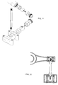
- a connecting rod that links to the swinging fork at its end, so that when one swinging fork ascends it causes a rotary motion of the balancer which, in turn, causes the swinging fork of the other end to descend, and vice versa (Fig. 4).
- the suitable hinged joint is the so-called "ball-and-socket" joint which, within some of the values, allows the connecting rods to form any angle with respect to the balancer and the swinging forks. Therefore, each end of the connecting rods will be provided with a ball joint having a diameter greater than that of the rod that links them. Inversely, each end of the balancer and each of the swinging forms must be provided with the corresponding sockets or openings that enable the housing, without too much play, of the connecting rods' ball joints.
- the axle that holds fast the balancer at its midpoint is parallel to the swinging forks and equidistant to them when the vehicle is in a vertical position or position of rest. It can be located at a higher or lower plane than that of the swinging forks, as mentioned earlier when describing the location of the balancer.
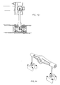
- connection of this axle to the vehicle's frame cannot be fixed or rigid, but in such a manner that it allows an oscillating upward/downward movement controlled by one only shock absorber, similar to the one used for modern motorcycles (Figs. 5 and 6).
- axle is connected to the vehicle's frame by means of a bracket to obtain its oscillating motion.
- Both, axle and bracket constitute one only piece which, in principle only, as we shall see, shall be of T-shape. Being this piece fastened to the vehicle's frame at its front ends (depending on th direction of travel), the rear end, the axle in the strictest sense, allows an up-and-down oscillating motion.
- the fastening of the ends of the brackets to the vehicle's frame must incorporate the pertinent antifriction bearings, that would allow the described motion without any resistance of whatsoever kind.
- axle and bracket can be of several shapes, in addition to the one already described. This will depend on a number of factors, among which must be mentioned the fastening of the shock absorber, according to the characteristics of the vehicle's performance.
- shape of the balancer, of the sockets or of the connecting rods can differ from the shapes suggested in the illustrations that accompany this description which, however, would not entail any modification of the operating principle of the invention nor be in detriment of its uniqueness.
- drum locking system shich the so-called drum locking system shich, as we will see, operates and actuates in a manner similar to that of the already known drum brake.
- the brake disc that incorporates the brake shoes, its guides, the shock-absorbent back springs, the drive cams and its axle, is installed in the front portion of the balancer's axle, as shown in Figure 27.
- the brake cam is actuated (Figs. 24 and 25)
- the shoes expand and rub against the drum, thus preventing that it rotates.
- the drum must be an integral part of the balancer, either forming one only element with it (Fig. 8) or being integrally linked to it.
- the piece constituted by the axle and the bracket must be necessarily of T-shape, but the element that up to now was acting as axle will become the axle's "guide" (Figs. 9 and 10).
- the balancer's axle will be inserted into this guide, with its fore protuding (depending on the vehicle's direction of travel) for the connection with the drum and with its rear extremity protruding for the connection with the balancer (Fig. 28).
- the brake disc with all of its components is located at the connection of the bracket and the front part of the axle's guide, as shown in Fig. 28.
- the vehicle provided with the "articulated balancer with an oscillating axle and having locking possibilities" provides more convenience and greater safety than a motorcycle without, however, losing its maneuverability or nature.
- the tilt angle with respect to the verticality of the vehicle is the same as that for a motorcycle which, barring an error, is of 32 o 32'.
- the tilt angle at which the force R is effective is not the only one but it also is susceptible to a range between R1 and R2, within which the vehicle maintains its balance.
- the maximum and minimum values of the tilt, barring an error would be 39 o 54' and 23 o 42', respectively.
- the vehicle with the balancer locked at a 32 o 32' tilt is capable to compensate a centrifugal force which for a motorcycle would require tilts between 23 o 42' and 39 o 54' that correspond to speeds between 74.68 m/h and 103.06 km/h for a 100 m radius of curve. In other words, for a speed of 90 km/h, without losing balance it allows for a variation of the radius of the curve between 145.2 meters and 76.2 meters.
- This invention consists of the following parts or elements: the balancer; ball joints of the balancer; connecting rods; ball joints of the swinging forks; the assembly of axle and bracket or the axle-bracket guide assembly; and, if applicable, the locking device.
- Figures 7 and 8 show ball bearings of angular contact with a double row of balls rollers at both ends of the balancer set in the recesses provided to this effect.
- the anfitrion bearings would be housed in the piece that forms the axle-bracket guide assembly. As shown in Figures 9 and 10, needle bearings are suggested for the front end and ball bearings for the rear end.
- the hinged joint must be suitably lubricated in order to minimize the frictions between the ball and the half-bearings. Also, the entering of dirt must be prevented by installing some type of rubber or plastic protection of bellows type that would not impair the play of the hinged joint.
- Figures 11, 12, 13 and 14 show, by way of indication, a system of adaptation that requires the disassembly of the two balls of each connecting rods. Both balls are tapped to the rod that connects them, this connection being secured by means of a small setscrew.
- the opening in each ball into which is inserted the setscrew allows also the immobilization of the ball once it is inserted into the ball joint, which allows a strong threading of the rod.
- a ball joint having the same function as that of the balancer, that is provided with the mentioned lubrication and rubber or plastic protectors.
- the options for the construction differ depending on the type of swinging forks used and on the chosen assembly system.
- the suggested solution for the connecting rod-swinging fork joint is identical to the one described for the connection rod-balancer.
- the ball joint of the swinging fork constructed independently of the latter, is inserted inside the swinging fork, which is hollow in the area in front of where it splits and is secured to it by means of screws or welds.
- the opening of the ball joint through which are inserted the half-bearings and the ball is located in the area of the splitting, as shown in Figure 4.
- this piece or rather, the assembly of pieces, can incorporate a coupling device or an arm for the coupling of the shock absorber and, if applicable, the brake disc for the locking of the balancer. If we also take into account that the axle can be an integral part or not of the balancer, we will understand that this assembly may be of the most varied types.
- the assembly will incorporate the axle and it may be of any of the types that, by way of indication, are shown in Figures 15, 17 and 19. If the mechanism is also provided with the device for the locking of the balancer's rotation, the assembly must also incorporate the brake disc, as shown in Figures 16, 18 and 20.
- the assembly comprises an upper arm for the coupling of the shock absorber.
- This type of assembly is deemed appropriate when the balancer is installed at a plane higher than that of the swinging forks, in order to avoid an excessive height for the fastening of the shock absorber to the vehicle's frame, due to that said shock absorber will be installed at a practically horizontal position (Fig. 21).
- the assembly does not comprise the axle, that is independent, but rather a guide for it.
- This option does make sense only if the mechanism comprises the locking device; therefore, the type of the axle guide-bracket assembly, shown in Figures 9 and 10, incorporates the brake disc.
- the upper arm of the coupling (Fig. 9) or the coupling device (Fig. 10) show us the method of fastening the shock absorber to the vehicle's frame, as explained above. In this option is impossible a lower arm for the direct coupling of the only shock absorber.
- the brake disc with all of its elements is located in the front portion of the axle itself, becoming an integral part of the described assembly.
- the drum will be connected to the balancer or will be an integral part of it.
- the balancer will be inserted on the axle that ends in a screw thread that allows, by means of one or more screws, its firm fastening to the assembly (Fig. 27).
- the brake disc with all of its elements is located in the front portion of the assembly, becoming a part of it.
- the axle which is independent of the assembly, is inserted in the guide, protruding from it with is front portion for the coupling of the brake drum, and with its rear portion for the coupling of the balancer (Fig. 28).
- the mechanism is also possible to design the mechanism as a system that combines the second and third claims, providing it with a double locking device (fourth claim).
- the axle guide-bracket assembly will be provided with to brake discs, one located in the front portion and the other one in the rear.
- the one of the front faces the independent drum that is fastened to the axle at its front end, and the one in the rear faces the drum that is incorporated into the balancer.
- This balancer will be fastened to the axle at its rear end (Fig. 32).
- the two options for the locking of the balancer's rotating can be used either jointly or separately.
- one option may be reserved for a manual locking and the other for an automatic locking. That is to say, one of option may be for a temporary locking during operation and the other one for permanent locking when parking the vehicle.
Abstract
Description
- THE ARTICULATED BALANCER WITH AN OSCILLATING AXLE AND HAVING LOCKING POSSIBILITIES is a mechanism, the purpose of which is to provide dynamic stability as well as static balance in curves to light-weight, narrow, wheeled vehicles having a high center of gravity. Its application, according to this paper, will focus on a vehicle having three wheels, one in the front and two in the rear, that could be related to a conventional motorcycle; this invention is directed to this sector of the industry.
- The purpose of the vehicle put forward herein is to combine the maneuverability of a motorcycle with higher levels of safety and convenience. Just like in the case of any motorcycle, the stability when taking a curve is obtained by a lateral shifting of its center of gravity, caused by the lateral tilting of the vehicle when approaching a curve.
- With respect to the above state of the art, the characteristic feature of any current vehicle having two wheels on the same wheels and axle assembly is that they are linked by one axle, whether rigid or not, real or imaginary, that maintains practically constant the distance between both wheels, and in which the oscillation of the wheels has the sole purpose of absorbing the irregularities of the terrain.
- In the vehicle equipped with the mechanism described herein, it is not possible to observe the existence of an axle between its rear wheels because, among other reasons, the distance between the centers of both wheels varies greatly with the inclination given to the vehicle. On the other hand, the essential function of the oscillation allowed for the rear wheels, in addition to absorbing the irregularities of the terrain, is to facilitate the lateral tilting of the vehicle, whether it is to one side or to the other according to the driver's requirement.
- Therefore, it is not a question of modifying or improving any of the techniques used in the manufacture of vehicle but rather that of applying a technique that, at least to the best knowledge of the inventor, is innovative.
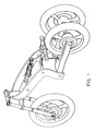
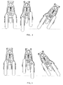
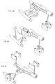
- To obtain the lateral tilting of the vehicle described herein (Fig. 1), it is necessary to provide each rear wheel with an upward/downward oscillating movement, so that when one the wheels rises the one other one descends to the same extent, thus causing the tilting of the vehicle (Figs. 2 and 3).
- Thus, the created technical problem consists in obtaining an appropriate performance of the vehicle's rear train, so that, although it consists of two wheels, it facilitates the lateral tilting of the vehicle, whether it is to one side or to the other according to the driver's requirement.
- To this effect, each of the rear wheels is connected to the frame of the vehicle by means of a swivel-mounted fork (hereinafter referred to as "swinging fork") similar to the one used in conventional motorcycles. Both swinging forks are held at their front end (according to the direction of travel of the vehicle) by one only axle, not linked to them, that is anchored to the frame at its lower rear portion in a transverse direction of travel. Each of the rear wheels has its own axle that is located at the rear end of each swinging fork.
- The only front wheel of the vehicle is connected to the frame by means of a hydraulic, telescopic fork, identical to the one used for conventional motorcycles, having also the same fastening and directional geometry.
- The described oscillating movement of the rear wheels is obtained by means of a lever, that we shall call "balancer", that at its midpoint is held fast by a axle, around which it rotates. The balancer is installed perpendicular to the swinging forks and, depending on the characteristics of performance required by the vehicle, it can be located on a plane that is either higher or lower than the plane of the swinging forks.
- At each end of the balancer is hinged a connecting rod that links to the swinging fork at its end, so that when one swinging fork ascends it causes a rotary motion of the balancer which, in turn, causes the swinging fork of the other end to descend, and vice versa (Fig. 4).
- Thus, it can be gathered that by means of the connecting rods the rotary motion of the balancer becomes an up-and-down motion of the swinging forks. Several factors must be taken into consideration for this transformation of movement. Thus, by way of example, the initial parallelism of the connecting rods is lost with the rotating of the balancer, due to that the latter is of fixed length; moreover, the angles formed by the connecting rod with the balancer or which the swinging forks are continuously modified by the action of the mechanism.
- It thus becomes necessary to provide it with an adequate system of hinged joints between its various elements to eliminate the stresses to which its performance could be exposed because of the constant modification of values and their ratios, thus obtaining a smooth and resistance-free transformation of movements.
- The suitable hinged joint is the so-called "ball-and-socket" joint which, within some of the values, allows the connecting rods to form any angle with respect to the balancer and the swinging forks. Therefore, each end of the connecting rods will be provided with a ball joint having a diameter greater than that of the rod that links them. Inversely, each end of the balancer and each of the swinging forms must be provided with the corresponding sockets or openings that enable the housing, without too much play, of the connecting rods' ball joints.
- As matter of course, the axle that holds fast the balancer at its midpoint is parallel to the swinging forks and equidistant to them when the vehicle is in a vertical position or position of rest. It can be located at a higher or lower plane than that of the swinging forks, as mentioned earlier when describing the location of the balancer.
- In order to be able to provide suspension to the vehicle's rear train, the connection of this axle to the vehicle's frame cannot be fixed or rigid, but in such a manner that it allows an oscillating upward/downward movement controlled by one only shock absorber, similar to the one used for modern motorcycles (Figs. 5 and 6).
- The axle is connected to the vehicle's frame by means of a bracket to obtain its oscillating motion. Both, axle and bracket, constitute one only piece which, in principle only, as we shall see, shall be of T-shape. Being this piece fastened to the vehicle's frame at its front ends (depending on th direction of travel), the rear end, the axle in the strictest sense, allows an up-and-down oscillating motion. As matter of course, the fastening of the ends of the brackets to the vehicle's frame must incorporate the pertinent antifriction bearings, that would allow the described motion without any resistance of whatsoever kind.
- Later we will see how the piece made-up of axle and bracket can be of several shapes, in addition to the one already described. This will depend on a number of factors, among which must be mentioned the fastening of the shock absorber, according to the characteristics of the vehicle's performance. In a similar manner, the shape of the balancer, of the sockets or of the connecting rods can differ from the shapes suggested in the illustrations that accompany this description which, however, would not entail any modification of the operating principle of the invention nor be in detriment of its uniqueness.
- The "articulated balancer with an oscillating axle", as heretofore described, shall be the subject of the first claim. However, the possibility of locking at wish the rotating of the balancer offers important applications, providing the vehicle with static balance or setting safety margins in dangerous situations. This possibility of locking is incorporated in the subsequent claims.
- The locking system appropriate for this invention because of its simplicity, low cost and suitable adaption is the so-called drum locking system shich, as we will see, operates and actuates in a manner similar to that of the already known drum brake.
- In this drum locking system (second claim), the brake disc, that incorporates the brake shoes, its guides, the shock-absorbent back springs, the drive cams and its axle, is installed in the front portion of the balancer's axle, as shown in Figure 27. When the brake cam is actuated (Figs. 24 and 25), the shoes expand and rub against the drum, thus preventing that it rotates. Obviously, the drum must be an integral part of the balancer, either forming one only element with it (Fig. 8) or being integrally linked to it.
- The only difference that can be noted with respect to the customary drum brake is the practically non-existing friction between the shoes and the drum which allows that the material of manufacture of the shoes be changed, as well as to provide the drum with a certain roughness or internal grooving in order to achieve, in this manner, effective locking with the smallest possible diameter of the drum.
- According to the heretofore description, it was deemed that the balancer and its axle were not jointly linked. It is feasible, however that both can be jointly linked which would entail that the piece made-up of the axle and its bracket be modified as well as a different location of the locking elements. This shall be the subject of the third claim.
- On this assumption, the piece constituted by the axle and the bracket must be necessarily of T-shape, but the element that up to now was acting as axle will become the axle's "guide" (Figs. 9 and 10). The balancer's axle will be inserted into this guide, with its fore protuding (depending on the vehicle's direction of travel) for the connection with the drum and with its rear extremity protruding for the connection with the balancer (Fig. 28). The brake disc with all of its components is located at the connection of the bracket and the front part of the axle's guide, as shown in Fig. 28.
- Compared with a conventional motorcycle, the vehicle provided with the "articulated balancer with an oscillating axle and having locking possibilities", provides more convenience and greater safety than a motorcycle without, however, losing its maneuverability or nature. With respect to its convenience, among others, can be mentioned the following advantages:
- 1) The driver must not hold the vehicle with his legs when he momentarily stops its operation because the vehicle maintains its verticality by itself since the rotation of the balancer is locked.
- 2) In view of the above reason, the vehicle allows very enveloping cowlings that assure great protection against cold weather and rain. Therefore, this mechanism is the ideal attachment for projects that, just like BMW's C-1, have the aim to develop vehicles that can be easily maneuvered in the chaotic city traffic without, however, having to renounce a minimum of safety and convenience.
- 3) It is not necessary to make any effort to park the vehicle, even on sloped road surfaces since it is not equipped with stands.
- 4) In the case of breakdowns, the vehicle can be easily pushed by hand without the risk that it would fall to one side. Moreover, due to that it stands on its own, the vehicle's cleaning and maintenance operations are easier to carry out.
- 5) The elimination of weight as the number one enemy of the motorist, will allow that the vehicle be provided with all sorts of elements that contribute to its convenience and safety: automatic locking devices for the balancer; an integral braking with only one foot control; an anti-locking system for the ABS brakes; fuel tanks of greater capacity; wider and more comfortable seats; etc.
- 6) The user friendliness of this vehicle is appropriate for automatic transmissions as well as "reverse" in most varied implementations.
- 7) The vehicle will inspire the driver with trust. This will make this type of vehicle accessible to a wide sector of users who are reluctant to get on a motorcycle.
- With respect to safety, the vehicle equipped with the "articulated balancer of oscillating axis and having locking possibilities", presents the following advantages with respect to any conventional motorcycle:
- 1) It considerably reduces the possibility of a rear train slipping (the most frequent one in the case of motorcycles), be it because of excessive speed in the curves or improper acceleration or braking when the vehicle is tilted.
- 2) If offers more traction in any situation and on any type of terrain, in particular when they are slippery.
- 3) It brakes better. To a better holding due to the third wheel, there must be added, in particular, a greater stability while braking.
- 4) The locking of the balance's rotation allows to maintain the balance of the vehicle in the case of slipping, additionally providing a safety margin in this and other dangerous situations.
- The stated advantages 1, 2 and 3 don't require an explanation, due to deeming them evident, but with respect to number 4 we shall enter into some details.
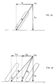
- Be looking at Fig. 34 we see that the balance of a conventional motorcycle requires that the force R, the resultant of the other two forces that must be considered (Fc = centrifugal force; Fw = weight of the vehicle) passes through the ideal line of points to the ground that connects the contact points wheels-to-ground. The driver achieves this by tilting, almost instinctively, at the exact angle that corresponds depending on the speed of the motorcycle and the radius of the curve he is taking. In this situation, any slight slippage of the front or rear assembly results in an immediate variation of the tilt angle, which causes the loss of balance and the subsequent mishap or accident.
- In the vehicle equipped with the invention set forth herein, if the driver realizes that the situation may become dangerous (excessive speed on wet ground, gravel, oily spots, etc.) he prepares to lock the balancer so that, in the case a slipping would occur, the vehicle's tilt angle would not be changed, thus maintaining the balance and facilitating its control. In vehicles equipped with ABS, this system could automatically lock the balancer's rotation when it detects any locking of the wheels or notes any difference in the rotating of the front and rear wheels.
- There exist other situations in which the locking of the balancer establishes a safety margin. Thus, an excessive speed when entering a curve, or a curve of variable radius taken at an improper speed, would compel the driver to tilt the motorcycle to a greater extent than he could be psychologically prepared, or more than advisable for the treadwear of the tires or the condition of the roadway. In such a situation, the driver, aware of the danger of slipping by applying the brake when tilting, tends to increase the radius of the curve resulting in a possible running off the roadway or an entering into the oncoming traffic lane.
- Under these circumstances, the locking of the balancer establishes, as we will see, a safety margin that allows to overcome such risks without the need of an excessive tilting of the vehicle; futhermore, the tires would operate within their best range of adherence.
- The following example will explain the foregoing. Assuming that the vehicle + driver have a weight of W = 250 kilograms; that the speed at which the vehicle travels is 90 km/hour (V = 25 meters/second); that r = 100 meters is the radius of the curve; that h = 0.5 meters is the height of the center of gravity with the vehicle in a vertical position; and that a = 0.36 meters is the width of the rear track gage being the vehicle in a vertical position.
- In a normal situation (free balancer), the tilt angle with respect to the verticality of the vehicle is the same as that for a motorcycle which, barring an error, is of 32º32'. However, as shown in Fig. 35, with the locked balancer, the tilt angle at which the force R is effective is not the only one but it also is susceptible to a range between R₁ and R₂, within which the vehicle maintains its balance.
- The higher or lower range of these values depends on the width of the rear track gage (a), on the previous tilt angle of the vehicle ( α ), on the heigh of the center of gravity of the vehicle (h), and on the point at which is said center of gravity with respect to the wheel base of the vehicle (d). In the above example, if we assume that the vehicle's center of gravity is located at the rear 2/3 of the vehicle's wheel base (measured from the center of the front wheel to the midpoint between the center of the rear wheels), we can calculate the maximum (B₁) and minimum (B₂) tilt values of R₁ and R₂ according to the below formula:

- In the above example, the maximum and minimum values of the tilt, barring an error, would be 39º54' and 23º42', respectively.
- This means that the vehicle with the balancer locked at a 32º32' tilt is capable to compensate a centrifugal force which for a motorcycle would require tilts between 23º42' and 39º54' that correspond to speeds between 74.68 m/h and 103.06 km/h for a 100 m radius of curve. In other words, for a speed of 90 km/h, without losing balance it allows for a variation of the radius of the curve between 145.2 meters and 76.2 meters.
- It is obvious that the manual locking of the balancer's rotating requires, just like everything, a certain degree of training. However, such locking can be done automatically. The possibility of linking such locking to the ABS system was discussed earlier but it can be supplemented with a microprocessor that by analyzing parameters, such as speed, tilt, centrifugal force, acceleration, deceleration, etc. determines the exact moment for the automatic locking and unlocking of the rotating of the balancer.
-
- The continuous references to illustrations made during the description have the purpose of making it understood. Therefore, we deem superfluous that special mention be made of their contents. However, it must be pointed out that the designs in Figures 1, 2, 3, 4, 21, 22 and 23 come close to the doctrine of the current motorcycle because of the following reasons:
- 1) Because in showing the adaptation, the validity of the invention is proven.
- 2) Because this invention is intended for the motorcycle manufacturing industry.
- 3) Because it shares many technical solutions with the conventional motorcycle.
- 4) Because the motorcycle constitutes the direct, indirect and comparative reference of the vehicle equipped with the mechanism set forth herein.
- 5) Because adapting the invention to motorcycles of the "scooter" type would hardly modify its external appearance, which makes them the most suitable candidate in the first stage of development.
- At this point of the description we will characterize two type of questions: first, those that refer to the construction of the "articulated balancer with oscillating axle and having locking possibilities", afterwards, a brief reference to adapting it to the suggested vehicle.
- This invention consists of the following parts or elements: the balancer; ball joints of the balancer; connecting rods; ball joints of the swinging forks; the assembly of axle and bracket or the axle-bracket guide assembly; and, if applicable, the locking device.
- Of solid, light-weight construction to prevent torsions and inertias, it is advisable that it be manufactured in one only piece which, depending on the construction, can be incorporated into the drum brake (Fig. 8) or not (Fig. 7). At the ends of the balancer will be installed the ball joints, reference to which will be made later.
- In case the balancer and its axle are not in one piece, there must be installed the appropriate antifriction bearings that will allow the balancer to rotate without resistance around the axle. By way of indication, Figures 7 and 8 show ball bearings of angular contact with a double row of balls rollers at both ends of the balancer set in the recesses provided to this effect.
- In case the balancer and its axle were one only piece, the anfitrion bearings would be housed in the piece that forms the axle-bracket guide assembly. As shown in Figures 9 and 10, needle bearings are suggested for the front end and ball bearings for the rear end.
- Located at both ends of the balancer, they are an integral part of it. In case the chosen system of adapting the hinged joint by means of "ball-and-socket" would require it, they must allow to be disassembled in order to insert into them the balls of the connecting rods. As an alternative, in case the balls of the connecting rods were removable, they could be laterally inserted into the ball joints of the balancer, being the ball roller held between spherical half-bearings, as shown in Figures 11 and 12.
- The hinged joint must be suitably lubricated in order to minimize the frictions between the ball and the half-bearings. Also, the entering of dirt must be prevented by installing some type of rubber or plastic protection of bellows type that would not impair the play of the hinged joint.
- There are two and their function is that of converting the rotary motion of the balancer to an up and down motion of the swinging forks or vice versa. At each of their ends they are provided with a ball with a diameter greater than that of the rod that connects them. One of the balls of each of the connecting rods is housed in the ball joint of the balancer while the other one is housed in the ball joint of the swinging fork at the same side. The balls can be removed or not, depending on the assembly system used for this type of hinged joint.
- Figures 11, 12, 13 and 14 show, by way of indication, a system of adaptation that requires the disassembly of the two balls of each connecting rods. Both balls are tapped to the rod that connects them, this connection being secured by means of a small setscrew. The opening in each ball into which is inserted the setscrew allows also the immobilization of the ball once it is inserted into the ball joint, which allows a strong threading of the rod.
- At each swinging fork in an area near the point where the fork splits is installed a ball joint having the same function as that of the balancer, that is provided with the mentioned lubrication and rubber or plastic protectors. The options for the construction differ depending on the type of swinging forks used and on the chosen assembly system.
- As shown in Figures 11 and 13, the suggested solution for the connecting rod-swinging fork joint is identical to the one described for the connection rod-balancer. The ball joint of the swinging fork, constructed independently of the latter, is inserted inside the swinging fork, which is hollow in the area in front of where it splits and is secured to it by means of screws or welds. The opening of the ball joint through which are inserted the half-bearings and the ball is located in the area of the splitting, as shown in Figure 4.
-
- As mentioned earlier, for the balancer to move up and down it must be fastened to the vehicle's frame by means of a bracket that is also provided with the appropriate antifriction bearings that enable such a motion (Fig. 5). As we will see, this piece, or rather, the assembly of pieces, can incorporate a coupling device or an arm for the coupling of the shock absorber and, if applicable, the brake disc for the locking of the balancer. If we also take into account that the axle can be an integral part or not of the balancer, we will understand that this assembly may be of the most varied types.
- In case the axle is not an integral part of the balancer, the assembly will incorporate the axle and it may be of any of the types that, by way of indication, are shown in Figures 15, 17 and 19. If the mechanism is also provided with the device for the locking of the balancer's rotation, the assembly must also incorporate the brake disc, as shown in Figures 16, 18 and 20.
- As shown in Figures 15 and 16, the assembly comprises an upper arm for the coupling of the shock absorber. This type of assembly is deemed appropriate when the balancer is installed at a plane higher than that of the swinging forks, in order to avoid an excessive height for the fastening of the shock absorber to the vehicle's frame, due to that said shock absorber will be installed at a practically horizontal position (Fig. 21).
- On the above assumption and with an identical purpose, there can be used the assembly illustrated in Figures 17 and 18 which, as it can be seen, comprises a lower arm for the coupling of the shock absorber, thus allowing to reduce the height at which it is fastened to the vehicle's frame (Fig. 22).
- Lastly, the type shown in Figures 19 and 20 proves to be the best for the fastening of the shock absorber in an almost vertical position when the balancer is located a lower plane than that of the swinging forks (Fig. 23).
- In case the axle is an integral part of the balancer, the assembly does not comprise the axle, that is independent, but rather a guide for it. This option does make sense only if the mechanism comprises the locking device; therefore, the type of the axle guide-bracket assembly, shown in Figures 9 and 10, incorporates the brake disc. The upper arm of the coupling (Fig. 9) or the coupling device (Fig. 10) show us the method of fastening the shock absorber to the vehicle's frame, as explained above. In this option is impossible a lower arm for the direct coupling of the only shock absorber.
- In all of the above suggestions it was assumed that the sole shock absorber would be directly fastened to the assembly. Nonetheless, the control of the oscillating motion of the balancer's axle can be carried out by means of a system of articulated connecting rods inserted between the assembly and the shock absorber. It is not deemed necessary to develop this possibility but only to mention it, since this aspect is not a part of the contents of the claims.
- Finally, it must be mentioned that the coupling of the assembly to the frame can be carried out by various means, one of which is shown, by way of indication in Figure 5 in which, as it can be seen, the entire assembly is fastened by means of two independent elements located at each end of the bracket that are screwed on to the vehicle's frame.
- It consists of the following elements:
- 1) The brake disc, that comprises the brake shoes, their guides, the shock-absorbent back springs, the drive cam and its axle (Fig. 24).
- 2) The brake disc against which rub the brake shoes when the drive cam is actuated (Fig. 25), thus preventing its rotating.
- Obviously, if the mechanism does not incorporate the possibility for a locking of the balancer's rotation (first claim), these elements become superfluous (Fig. 26). If however, this possibility is given, the location of these elements shall differ depending on whether the balancer is an integral part or not of its axle.
- In case the axle is not an integral part of the balancer (second claim), the brake disc with all of its elements is located in the front portion of the axle itself, becoming an integral part of the described assembly. The drum will be connected to the balancer or will be an integral part of it. The balancer will be inserted on the axle that ends in a screw thread that allows, by means of one or more screws, its firm fastening to the assembly (Fig. 27).
- In case the axle is an integral part of the balancer (third claim), the brake disc with all of its elements is located in the front portion of the assembly, becoming a part of it. The axle, which is independent of the assembly, is inserted in the guide, protruding from it with is front portion for the coupling of the brake drum, and with its rear portion for the coupling of the balancer (Fig. 28).
- It is also possible to design the mechanism as a system that combines the second and third claims, providing it with a double locking device (fourth claim). In this case, the axle guide-bracket assembly will be provided with to brake discs, one located in the front portion and the other one in the rear. The one of the front faces the independent drum that is fastened to the axle at its front end, and the one in the rear faces the drum that is incorporated into the balancer. This balancer will be fastened to the axle at its rear end (Fig. 32).
- The two options for the locking of the balancer's rotating can be used either jointly or separately. In the latter case, one option may be reserved for a manual locking and the other for an automatic locking. That is to say, one of option may be for a temporary locking during operation and the other one for permanent locking when parking the vehicle.
- With this we deem as concluded one method of construction of the "articulated balancer with oscillating axle having locking possibilities". However, in its adaption to the vehicle set forth herein, we deem necessary some considerations:
- A) In view of the considerable oscillation to may be reached by the rear wheels of the vehicle if it carries the driver and one passenger, the adoption of all or of some of the below measures, or a combination thereof, is recommended with respect to a conventional motorcycle: a lengthening of 15 or 20 centimeters of the wheel base; the use of rear wheels of less diameter; a slight moving forward of the driver's position and a somewhat higher positioning of the passenger seat.
- B) Because of the same reason (oscillating of the rear wheels), the secondary chain drive (or pulley) recommends that the drive pinions be located on the axle of the swinging forks, whereby a constant tension would be obtained in any situation, which would make unnecessary the use of tension devices. Both drive pinions would be actuated by a third pinion, located at a central position with respect to them, that would be the one receiving the driving force.
- C) Although the width of the vehicle's gage is small (for example, between 20 and 45 centimeters), the different running in the curves of each of the rear wheels requires the adopting of some sort of mechanism in order to release the tensions produced in the transmission. If, as recommended in the foregoing consideration, the pinions are located on the same axle as the swinging forks, between the central pinion and any of the lateral pinions, but simultaneously only with one of them, the possibility of a limited different rotating must be recognized. If the drive pinions were located in the engine, some type of the differential or a similar mechanism must be installed in the engine.
- D) The locking of the balancer's rotating in a curve subjects the swinging forks and the rear wheels to greater stresses than in a conventional motorcycle. Therefore, the swinging forks must offer a greater resistance to the torsion; the rims must be of a light-weight alloy instead of radial and the tires shall be of a low profile to avoid their slipping off the rim.
- E) The width of the rear gage increases with the tilt given to the vehicle, according to the formula

Claims (4)
- FIRST - ARTICULATED BALANCER WITH OSCILLATING AXLE, designed as a mechanism intended to provide dynamic stability in curves to light-weight, narrow vehicles having a high center of gravity, equipped with three wheels, one in the front and two in the rear. By means of two connecting rods with hinged joints of "ball-and-socket" type, the rotary motion of the balancer around its axle is converted into an up and down motion of the rear wheels, which allows a lateral tilting of the vehicle when approaching a curve, thus compensating the existing centrifugal force. The rear suspension is made feasible by according the balancer's axle an up and down oscillating motion.
It consists of the following parts or elements:- BALANCER, which is a lever held at its midpoint by an axle, of which it is not an integral part, around which it rotates. It is located perpendicular to the swinging forks on either a higher or lower plane than theirs. Inside of it are located antifriction bearings.- BALANCER'S BALL JOINTS, located at the ends of the balancer, forming an integral part of it. They allow the linkage by "ball-and-socket" between the balancer and the connecting rods.- Two CONNECTING RODS for the purpose of converting the rotary motion of the balancer to an up-and-down motion of the rear swinging forks, or vice versa, by means of "ball-and-socket" hinged joints.- BALL JOINTS OF THE SWINGING FORKS, one for each swinging fork into which it is inserted, that allow the linkage by "ball-and-socket" between the connecting rods and the swinging forks.- AXLE-BRACKET ASSEMBLY, intended for the holding of the balancer at its midpoint, allowing it further an up-and-down oscillating motion. It also comprises the latching arm or device for the connecting of the shock absorber.
Its operating characteristics, the connection between its elements and the adapting of the vehicle are set forth in the above description, of which one of its types of construction can be seen from Figure 29. - SECOND - ARTICULATED BALANCER WITH OSCILLATING AXLE AND HAVING LOCKING POSSIBILITIES, designed as a mechanism intended to provide dynamic stability and static balance in curves to light-weight, narrow vehicles having a high center of gravity, equipped with three wheels, one in the front and two in the rear. By means of two connecting rods with hinged joints of "ball-and-socket" type, the rotary motion of the balancer around its axle is converted into an up and down motion of the rear wheels, which allows a lateral tilting of the vehicle when approaching a curve, thus compensating the existing centrifugal force. The rear suspension is made feasible by according the balancer's axle an up and down oscillating motion. The static balance and certain characteristics of its dynamic behavior are obtained by locking the rotating of the balancer.
It consists of the following parts or elements:- BALANCER, which is a lever held at its midpoint by an axle, of which it is not an integral part, around which it rotates. It is located perpendicular to the swinging forks on either a higher or lower plane than theirs. In its front portion it incorporates the drum which, facing the brake disc, makes feasible the locking of its rotation. Inside of it are housed antifriction bearings.- BALANCER'S BALL JOINTS; same as in the first claim.- CONNECTING RODS; same as in the first claim.- BALL JOINTS OF THE SWINGING FORKS; same as in the first claim.- AXLE-BRACKET ASSEMBLY, intended to hold the balancer at its midpoint, allowing it furthermore an up-and-down oscillating motion. It also comprises the latching arm or device for the connecting of the shock absorber, as well as the brake disc with all of its elements.- LOCKING DEVICE, of operation and actuating analogous to the traditional brake drum, intended to prevent the balancer from rotating. It consists of two elements: the brake disc and the brake drum. The disc with all of its elements is located in the axle-bracket assembly while the drum is located in the balancer.
Its operating characteristics, the connection between its elements and the adapting to the vehicle are set forth in the above description, of which one of its types of construction can be seen from Figure 30. - THIRD - ARTICULATED BALANCER WITH OSCILLATING AXLE AND HAVING LOCKING POSSIBILITIES.
It consists of the following parts or elements:- BALANCER, which is a lever held at its midpoint by an axle, of which it is not an integral part, around which it rotates. It is located perpecdicular to the swinging forks on either a higher or lower plane than theirs.- BALANCER'S BALL JOINTS; same as in the first claim.- CONNECTING RODS; same as in the first claim.- BALL JOINTS OF THE SWINGING FORKS; same as in the first claim.- AXLE GUIDE-BRACKET ASSEMBLY, intended to house the balancer's axle and to function as its guide, allowing it furthermore an up-and-down oscillating motion. It also comprises the latching arm or device for the connecting of the shock absorber, as well as the brake disc with all of its elements. Inside of it are housed antifriction bearings.- AXLE, that is a cylindrical rod of high resistance to torsion and grooved at its ends, that is inserted into the axle guide, from which it protrudes with its front end for the integral connection of the drum, and protrudring with its rear end for an integral connection of the balancer.- LOCKING DEVICE, of operation and actuating analogous to the traditional brake drum, intended to prevent the balancer from rotating. It consists of two elements: the brake disc and the brake drum. The disc with all of its elements is located with its front portion in the axle-bracket assembly; the drum, as an independent element that faces the disc makes feasible the locking of the rotating of the balancer, to which it is connected by means of the axle.
Its operating characteristics, the connection between its elements and the adapting of the vehicle are set forth in the above description, of which one of its types of construction can be seen from Figure 31. - FOURTH - ARTICULATED BALANCER WITH OSCILLATING AXLE AND HAVING LOCKING POSSIBILITIES.
Designed as a system combining claims two and three, it is provided with a dual device for the locking of the rotating of the balancer. It consists of the following parts or elements:- BALANCER, which is a lever held at its midpoint by an axle, of which it is not an integral part, around which it rotates. It is located perpendicular to the swinging forks on either a higher or lower plane than theirs. In its front portion it incorporates a drum which, facing the rear brake disc of the axle guide-bracket assembly, allows the first locking option.- BALANCER'S BALL JOINTS; same as in the first claim.- CONNECTING RODS; same as in the first claim.- BALL JOINTS OF THE SWINGING FORKS; same as in the first claim.- AXLE GUIDE-BRACKET ASSEMBLY, intended to house the balancer's axle and to function as its guide, allowing it furthermore an up-and-down oscillating motion. It also comprises the latching arm or device for the connecting of the shock absorber, as well as the brake discs with all of their elements, one of which located in the front portion of the assembly and the other one in its rear portion. Inside the assembly are housed antifriction bearings.- AXLE; same as in the third claim.- DUAL LOCKING DEVICE, of operation and actuating analogous to the traditional brake drum, intended to prevent the balancer from rotating. Each of the devices consists of two elements: the brake disc and the brake drum. The two discs are located in the axle guide-bracket assembly, as indicated. The two drums face the discs: the one in the front, as an independent element integrally connected to the axle at its front end; the one in the rear, forming part of the balancer, as indicated.
Its operating characteristics, the connection between its elements and the adapting to the vehicle are set forth in the above description, of which one of its types of construction can be seen from Figure 33.
Applications Claiming Priority (2)
| Application Number | Priority Date | Filing Date | Title |
|---|---|---|---|
| ES9300004 | 1993-01-04 | ||
| ES09300004A ES2064251B1 (en) | 1993-01-04 | 1993-01-04 | ARTICULATED BALANCER WITH SWING AXLE AND POSSIBILITY OF LOCKING. |
Publications (2)
| Publication Number | Publication Date |
|---|---|
| EP0606191A1 true EP0606191A1 (en) | 1994-07-13 |
| EP0606191B1 EP0606191B1 (en) | 1997-03-19 |
Family
ID=8280383
Family Applications (1)
| Application Number | Title | Priority Date | Filing Date |
|---|---|---|---|
| EP94500001A Expired - Lifetime EP0606191B1 (en) | 1993-01-04 | 1994-01-03 | Wheeled vehicle comprising an oscillating axle and an articulated rocking lever having locking possibilities |
Country Status (4)
| Country | Link |
|---|---|
| US (1) | US5611555A (en) |
| EP (1) | EP0606191B1 (en) |
| DE (1) | DE69402087T2 (en) |
| ES (1) | ES2064251B1 (en) |
Cited By (27)
| Publication number | Priority date | Publication date | Assignee | Title |
|---|---|---|---|---|
| FR2755933A1 (en) * | 1996-11-15 | 1998-05-22 | Pudlo Michel | Stabilising frame for motor bicycles |
| WO1998043872A1 (en) * | 1997-04-02 | 1998-10-08 | Protos S.R.L. | Three wheeled vehicle with tilting system |
| EP0911248A3 (en) * | 1997-10-21 | 1999-10-27 | Kleine Borgmann, Beatrix | Two-wheel vehicle |
| FR2792274A1 (en) | 1999-04-14 | 2000-10-20 | Jean Philippe Minot | VEHICLE WITH GUIDED VARIABLE PENDULARITY |
| FR2794096A1 (en) * | 1999-05-28 | 2000-12-01 | Roger Philippe Boedec | REAR WHEEL MOBILITY SYSTEM FOR A 3-WHEEL BIKE RECOVERY WITH MORE THAN 45 DEGREES |
| EP1070658A1 (en) * | 1999-07-23 | 2001-01-24 | Aprilia S.P.A. | Mechanism for the construction of a three-wheeled vehicle with front rolling part |
| EP1346907A2 (en) | 2002-03-20 | 2003-09-24 | Benelli S.p.A. | A suspension for twinned swing-axle wheels of a tilting vehicle |
| FR2841870A1 (en) | 2002-07-05 | 2004-01-09 | Philippe Francois Girardi | Suspension system for three-wheeled vehicle that can tilt on bends has force transmission member between transverse connecting bar and dampers |
| AT500255A1 (en) * | 2003-11-21 | 2005-11-15 | Berghofer Alfred | REAR SUSPENSION WITH VEHICLE TILTING UNIT FOR VEHICLE |
| EP1362779A3 (en) * | 2002-05-17 | 2006-04-12 | Nicholas Richard Shotter | Motorcycle-type vehicles |
| EP1884457A1 (en) | 2006-07-26 | 2008-02-06 | Yamaha Motor Europe N.V. | Motorcycle |
| WO2008052539A1 (en) * | 2006-10-30 | 2008-05-08 | Hektor Steinhilber | Vehicle with three wheels |
| GB2450740A (en) * | 2007-07-05 | 2009-01-07 | Andrei Zavolnyi | Three-wheeled motor vehicle |
| WO2011074204A1 (en) * | 2009-12-17 | 2011-06-23 | ヤマハ発動機株式会社 | Straddle-ridden vehicle |
| FR2971734A1 (en) * | 2011-02-17 | 2012-08-24 | Peugeot Citroen Automobiles Sa | Vehicle i.e. motor vehicle, has single rear suspension arm connecting rear wheels with chassis, and controlled actuating unit arranged with controlled actuator to modify side inclination of suspension arm with respect to rear wheels |
| WO2012160323A2 (en) | 2011-05-20 | 2012-11-29 | Nicholas Richard Shotter | Front suspension system |
| WO2013186572A1 (en) * | 2012-06-16 | 2013-12-19 | Wizz Mobility Limited | Improvements in and relating to attendant propelled vehicles |
| CN105599839A (en) * | 2015-09-08 | 2016-05-25 | 嵊州市中工电气有限公司 | Scooter |
| GB2533477A (en) * | 2014-11-26 | 2016-06-22 | Ford Global Tech Llc | Suspension systems for laterally tiltable multitrack vehicles |
| CN106005119A (en) * | 2016-04-01 | 2016-10-12 | 上海易吉动力科技有限公司 | Rear wheel balance tricycle having seat shock absorbing function |
| CN106005173A (en) * | 2016-04-01 | 2016-10-12 | 上海易吉动力科技有限公司 | Tricycle adopting double-wheel interaction-balance system |
| US9809273B2 (en) | 2014-02-12 | 2017-11-07 | Royalty Bugaboo Gmbh | Foldable vehicle |
| US9821620B2 (en) | 2014-09-01 | 2017-11-21 | Ford Technologies Corporation | Method for operating a tilting running gear and an active tilting running gear for a non-rail-borne vehicle |
| US9845129B2 (en) | 2014-08-29 | 2017-12-19 | Ford Global Technologies, Llc | Stabilizing arrangement for a tilting running gear of a vehicle and tilting running gear |
| US9925843B2 (en) | 2015-02-24 | 2018-03-27 | Ford Global Technologies, Llc | Rear suspension systems for laterally tiltable multitrack vehicles |
| US10023019B2 (en) | 2015-02-24 | 2018-07-17 | Ford Global Technologies, Llc | Rear suspension systems with rotary devices for laterally tiltable multitrack vehicles |
| WO2022074362A1 (en) | 2020-10-08 | 2022-04-14 | Momentum Scooters Ltd | Wheeled vehicle with tilt control |
Families Citing this family (81)
| Publication number | Priority date | Publication date | Assignee | Title |
|---|---|---|---|---|
| US5941548A (en) * | 1995-08-25 | 1999-08-24 | Owsen; Peter | Non-tipping tricycle having releasable locking mechanism between the front and rear frames |
| US6105986A (en) * | 1997-08-11 | 2000-08-22 | Franks; Jon | Handcycle |
| US6554086B1 (en) * | 2000-10-27 | 2003-04-29 | Invacare Corporation | Obstacle traversing wheelchair |
| TW518299B (en) * | 2000-10-31 | 2003-01-21 | Mel Ton Internat L L C | Tricycle |
| DE10060663C1 (en) * | 2000-12-06 | 2002-01-31 | Wolfram Gorisch | Multi-track rollers, such as roller skates, scooters, comprise base plate, rollers mounted on bearing blocks, transverse links, linkages, and swivel axles. |
| US7040429B2 (en) * | 2001-10-10 | 2006-05-09 | Invacare Corporation | Wheelchair suspension |
| US7066290B2 (en) | 2001-10-19 | 2006-06-27 | Invacare Corp. | Wheelchair suspension having pivotal motor mount |
| US20030102176A1 (en) * | 2001-12-03 | 2003-06-05 | Bautista Eric Saqueton | Vehicle with a stabilized tilting section |
| US20030214113A1 (en) * | 2002-05-02 | 2003-11-20 | Todd Bank | Vehicle having independently articulating rear frame members |
| US20040032119A1 (en) * | 2002-05-29 | 2004-02-19 | Sy Tran | Control of an anti-tip wheel in wheelchairs |
| DE60319307T2 (en) * | 2002-07-05 | 2008-06-12 | Honda Giken Kogyo K.K. | Tricycle with engine and tilt mechanism |
| ES2398560T3 (en) * | 2002-08-16 | 2013-03-20 | Invacare Corporation | Vehicle that has an anti-sinking / locking mechanism |
| US6851711B2 (en) * | 2002-08-16 | 2005-02-08 | Invacare Corporation | Vehicle having an anti-dive/lockout mechanism |
| US11213441B2 (en) | 2002-10-25 | 2022-01-04 | Invacare Corporation | Suspension for wheeled vehicles |
| US7083195B2 (en) * | 2002-10-25 | 2006-08-01 | Invacare Corporation | Suspension with releasable locking system |
| US7293801B2 (en) * | 2003-08-18 | 2007-11-13 | Invacare Corporation | Self-stabilizing suspension for wheeled vehicles |
| JP4287136B2 (en) * | 2002-12-20 | 2009-07-01 | 本田技研工業株式会社 | Vehicle suspension arrangement structure |
| EP1572526B1 (en) * | 2002-12-20 | 2010-04-21 | Roald H. Pedersen | Vehicle with a titltable chassis |
| US7097187B2 (en) * | 2002-12-20 | 2006-08-29 | Daimlerchrysler Corporation | Suspension system for a motor vehicle |
| US8672102B2 (en) * | 2002-12-20 | 2014-03-18 | Chrysler Group Llc | Brake system for a motor vehicle |
| KR100530031B1 (en) * | 2003-11-11 | 2005-11-21 | 현대모비스 주식회사 | torsion beam axle suspension |
| US9487234B1 (en) | 2003-12-09 | 2016-11-08 | Mystery Designs, LLC | Control system for tilting motorcycle trike |
| US10144475B2 (en) | 2003-12-09 | 2018-12-04 | Mystery Designs, LLC | Control system for tilting motorcycle trike |
| US7343997B1 (en) * | 2003-12-09 | 2008-03-18 | Lawayne Matthies | Tilting independent suspension system for motorcycle trike |
| CN1319803C (en) * | 2004-07-01 | 2007-06-06 | 张向阳 | Light tricycle and its frame |
| SG126786A1 (en) * | 2005-04-19 | 2006-11-29 | Singapore Technologies Kinetic | A three-wheeled vehicle adaptable for different purposes |
| WO2006121495A2 (en) * | 2005-05-05 | 2006-11-16 | Purdue Research Foundation | Vehicle with variable wheel camber |
| US7543829B1 (en) * | 2005-06-24 | 2009-06-09 | Danny Barnes | Three wheel coaster cycle |
| US20070007739A1 (en) * | 2005-07-09 | 2007-01-11 | Bailey Eric S | Steerable Carriage Apparatus |
| US7487985B1 (en) * | 2005-08-25 | 2009-02-10 | Robert Mighell | Tilting wheeled vehicle |
| US7845666B2 (en) * | 2006-03-06 | 2010-12-07 | Purdue Research Foundation | Swinging hub for adjusting wheel camber |
| DE102006052041B4 (en) * | 2006-10-30 | 2009-07-30 | Steinhilber, Hektor | Vehicle with three wheels |
| EP1943995A1 (en) * | 2007-01-12 | 2008-07-16 | Invacare International Sàrl | A wheeled conveyance with suspension arms for wheels |
| CN102499827B (en) | 2007-02-08 | 2015-11-25 | 英瓦卡尔公司 | Wheelchair suspension |
| DK2340800T3 (en) | 2007-02-14 | 2013-07-22 | Invacare Corp | STABILITY MANAGEMENT SYSTEM |
| DE102008008731A1 (en) | 2008-02-11 | 2009-08-13 | Kochlik, Klaus, Dipl.-Ing. | Three-wheeled vehicle, has rear wheel driven by engine, and connectors sliding into guide shaft, which is fastened at vehicle frame, where wheels are moved up and down with respect to vehicle frame to ensure bending of vehicle |
| JP5204637B2 (en) * | 2008-12-16 | 2013-06-05 | ヤマハ発動機株式会社 | Saddle riding vehicle |
| US8376372B2 (en) * | 2009-02-16 | 2013-02-19 | Kinya Kanou | Multiple wheel vehicle |
| GB0906909D0 (en) * | 2009-04-22 | 2009-06-03 | Tube Plastics Ltd | Recreational vehicle |
| US8177013B2 (en) * | 2009-05-28 | 2012-05-15 | Liang Chang | Motorcycle rear-wheels transmission and suspension system |
| US20100320023A1 (en) * | 2009-06-23 | 2010-12-23 | Michael Rhodig | Four wheel vehicle having a rotatable body section and method therefor |
| US8480106B1 (en) * | 2009-07-23 | 2013-07-09 | The George Washington University | Dual suspension system |
| DE102009042662A1 (en) * | 2009-09-23 | 2011-03-24 | Bayerische Motoren Werke Aktiengesellschaft | Drive module for use with pendulum axle for motor vehicle, particularly for tricycle, comprises wheel, which is attached at end, around transverse axis lying at other end, particularly fastened at frame by suspension strut |
| US9010470B2 (en) | 2009-10-09 | 2015-04-21 | Invacare Corporation | Wheelchair suspension |
| FR2961783B1 (en) * | 2010-06-23 | 2012-08-03 | Veleance | DEVICE FOR MONITORING THE INCLINATION OF A FRAME MOUNTED ON A RECLINING BEARING TRAIN |
| ES2384347B1 (en) * | 2010-12-07 | 2013-05-16 | Stilz Automotive Galicia, S.L. | REAR SUSPENSION SYSTEM FOR THREE-WHEELED VEHICLES |
| US20130062854A1 (en) * | 2011-09-14 | 2013-03-14 | Caterpillar Inc. | Torsion suspension system |
| US11407466B2 (en) | 2011-09-16 | 2022-08-09 | Arcimoto, Inc. | Tilting wheeled vehicle |
| US8382135B1 (en) * | 2011-10-17 | 2013-02-26 | William J Raike, III | Sand-rideable bicycle |
| US9284009B2 (en) | 2011-10-17 | 2016-03-15 | William J. Raike, III | Sand-rideable bicycle with positive traction gear assembly |
| US20130193668A1 (en) * | 2012-01-20 | 2013-08-01 | Ronald Decker | Adult tricycle |
| EP2814441B9 (en) | 2012-02-15 | 2017-11-15 | Invacare Corporation | Wheelchair suspension |
| DE102012019010A1 (en) | 2012-09-27 | 2014-03-27 | Hochschule RheinMain | Vehicle e.g. motorcycle has tilting frame whose upper and lower end is provided with pair of oppositely arranged wheels that are tilted on all axes along inclination angle |
| DE102014201127B4 (en) | 2013-03-07 | 2022-02-03 | Ford Global Technologies, Llc | Side-tilting, multi-track vehicle |
| DE102014201630B4 (en) | 2013-03-07 | 2021-09-02 | Ford Global Technologies, Llc | Laterally tiltable, multi-lane vehicle |
| DE102014201670A1 (en) | 2013-03-07 | 2014-09-11 | Ford Global Technologies, Llc | Sideways inclinable, multi-lane vehicle |
| DE102014201668B4 (en) | 2013-03-07 | 2021-09-02 | Ford Global Technologies, Llc | Laterally tiltable, multi-lane vehicle |
| DE102014201632B4 (en) | 2013-03-07 | 2021-09-02 | Ford Global Technologies, Llc | Laterally tiltable, multi-lane vehicle |
| US9327725B2 (en) * | 2013-05-28 | 2016-05-03 | Eric N. Anderfaas | Geometry for improved driveline-suspension coupling of narrow leaning commuter vehicles |
| JP5707008B1 (en) * | 2013-07-01 | 2015-04-22 | ヤマハ発動機株式会社 | vehicle |
| DE102014008620B4 (en) | 2014-06-07 | 2020-12-10 | Audi Ag | Chassis system of a vehicle and method for lifting at least one vehicle wheel of a vehicle |
| UA110878C2 (en) * | 2014-08-14 | 2016-02-25 | Юрій Львович Беседовський | Rear wheel suspension of the vehicle |
| CN204077952U (en) * | 2014-09-23 | 2015-01-07 | 捷安特(昆山)有限公司 | Cycle frame |
| TWI600565B (en) * | 2015-05-25 | 2017-10-01 | For steering gear with two front wheel carrier | |
| CH711724A2 (en) * | 2015-11-04 | 2017-05-15 | Armec Mech Ag | Rear suspension for a bendable in the curve vehicle. |
| CN107176254A (en) * | 2016-03-11 | 2017-09-19 | 扬顶(天津)商贸有限公司 | A kind of three-wheel above motorcycle pressure control vehicle frame and wheel autobalance |
| DE202016004580U1 (en) * | 2016-07-25 | 2016-10-27 | Liebherr-Werk Ehingen Gmbh | Axle |
| DE102017105869A1 (en) * | 2017-03-20 | 2018-09-20 | Schaeffler Technologies AG & Co. KG | shock absorber |
| JP6153049B1 (en) * | 2017-03-25 | 2017-06-28 | 株式会社スタイルヤマモト | Three-wheeled vehicle |
| CN107878642B (en) * | 2017-11-30 | 2023-05-26 | 浙江逗哈科技股份有限公司 | Automatic standing device and swing type vehicle with same |
| US10800476B1 (en) | 2017-12-17 | 2020-10-13 | John Suratana Thienphrapa | Motorized cycle |
| NL2020889B1 (en) * | 2018-05-08 | 2019-05-22 | Royalty Bugaboo Gmbh | Improved tilting suspension for a vehicle |
| US20200223279A1 (en) * | 2019-01-10 | 2020-07-16 | Nio Usa, Inc. | Anti-roll bar with heave spring or actuator |
| KR102541039B1 (en) * | 2019-05-02 | 2023-06-08 | 현대자동차주식회사 | Tilting structure of mobility device and mobility device incluiding the same |
| AT523346A1 (en) * | 2019-08-28 | 2021-07-15 | Gleam Tech Gmbh | Vehicle with tilting mechanism |
| CN110901318B (en) * | 2019-12-23 | 2022-02-18 | 浙江涛涛车业股份有限公司 | Vehicle suspension system and vehicle |
| JP7373989B2 (en) * | 2019-12-26 | 2023-11-06 | カワサキモータース株式会社 | lean vehicle |
| EP4110257A4 (en) | 2020-02-25 | 2024-03-06 | Invacare Corp | Wheelchair and suspension systems |
| CN113086069B (en) * | 2021-05-13 | 2022-11-29 | 叶奇正 | Positive tricycle storage battery car |
| US11383792B1 (en) | 2021-08-27 | 2022-07-12 | John Suratana Thienphrapa | Motorized cycle |
| KR20230133094A (en) * | 2022-03-10 | 2023-09-19 | 현대자동차주식회사 | Mobility |
Citations (5)
| Publication number | Priority date | Publication date | Assignee | Title |
|---|---|---|---|---|
| FR1562248A (en) * | 1968-02-22 | 1969-04-04 | ||
| FR2277261A1 (en) * | 1974-07-05 | 1976-01-30 | Anvar | BLOCKABLE JOINT |
| FR2550507A1 (en) * | 1983-08-11 | 1985-02-15 | Devaux Pierre | Motorised tricycle with independent rear wheels |
| FR2616405A1 (en) * | 1987-06-11 | 1988-12-16 | Perrin Louis | MOTORIZED TRICYCLE WITH INDEPENDENT REAR WHEELS |
| US4887829A (en) * | 1987-04-07 | 1989-12-19 | Prince Curtis L | Rear wheel suspension system for a tricycle vehicle |
Family Cites Families (10)
| Publication number | Priority date | Publication date | Assignee | Title |
|---|---|---|---|---|
| FR1085100A (en) * | 1953-06-18 | 1955-01-27 | Vehicle suspension | |
| US2819093A (en) * | 1954-09-16 | 1958-01-07 | Homer E Geiser | Suspension mechanism for motor driven vehicles and the like |
| NL163749C (en) * | 1968-02-22 | 1980-10-15 | Anvar | TRI-WHEEL VEHICLE WITH REAR AXLE PIVOT CHASSIS. |
| US3572456A (en) * | 1969-01-09 | 1971-03-30 | Arthur D Healy | Bankable tricycle type vehicle |
| US3866341A (en) * | 1973-05-24 | 1975-02-18 | Joe H Fabrygel | Scraper bucket with tiltable axle assembly |
| US4003443A (en) * | 1975-07-31 | 1977-01-18 | Gordon Neal Boughers | Multiple wheel motorcycle suspension and drive system |
| US4088199A (en) * | 1976-02-23 | 1978-05-09 | Wolfgang Trautwein | Stabilized three-wheeled vehicle |
| US4375295A (en) * | 1979-04-20 | 1983-03-01 | Frank Volin | Detachable wheelchair backrest |
| FR2600612B1 (en) * | 1986-06-27 | 1990-11-30 | Patin Pierre | STABILIZATION METHOD AND DEVICES FOR A TILTING VEHICLE |
| FR2639016B1 (en) * | 1988-11-15 | 1991-02-08 | Patin Pierre | STABILIZATION DEVICE FOR TILTING VEHICLE |
-
1993
- 1993-01-04 ES ES09300004A patent/ES2064251B1/en not_active Expired - Fee Related
-
1994
- 1994-01-03 EP EP94500001A patent/EP0606191B1/en not_active Expired - Lifetime
- 1994-01-03 US US08/177,082 patent/US5611555A/en not_active Expired - Fee Related
- 1994-01-03 DE DE69402087T patent/DE69402087T2/en not_active Expired - Fee Related
Patent Citations (5)
| Publication number | Priority date | Publication date | Assignee | Title |
|---|---|---|---|---|
| FR1562248A (en) * | 1968-02-22 | 1969-04-04 | ||
| FR2277261A1 (en) * | 1974-07-05 | 1976-01-30 | Anvar | BLOCKABLE JOINT |
| FR2550507A1 (en) * | 1983-08-11 | 1985-02-15 | Devaux Pierre | Motorised tricycle with independent rear wheels |
| US4887829A (en) * | 1987-04-07 | 1989-12-19 | Prince Curtis L | Rear wheel suspension system for a tricycle vehicle |
| FR2616405A1 (en) * | 1987-06-11 | 1988-12-16 | Perrin Louis | MOTORIZED TRICYCLE WITH INDEPENDENT REAR WHEELS |
Cited By (38)
| Publication number | Priority date | Publication date | Assignee | Title |
|---|---|---|---|---|
| FR2755933A1 (en) * | 1996-11-15 | 1998-05-22 | Pudlo Michel | Stabilising frame for motor bicycles |
| WO1998043872A1 (en) * | 1997-04-02 | 1998-10-08 | Protos S.R.L. | Three wheeled vehicle with tilting system |
| EP0911248A3 (en) * | 1997-10-21 | 1999-10-27 | Kleine Borgmann, Beatrix | Two-wheel vehicle |
| FR2792274A1 (en) | 1999-04-14 | 2000-10-20 | Jean Philippe Minot | VEHICLE WITH GUIDED VARIABLE PENDULARITY |
| FR2794096A1 (en) * | 1999-05-28 | 2000-12-01 | Roger Philippe Boedec | REAR WHEEL MOBILITY SYSTEM FOR A 3-WHEEL BIKE RECOVERY WITH MORE THAN 45 DEGREES |
| WO2000073127A1 (en) * | 1999-05-28 | 2000-12-07 | Roger Boedec | Rear wheel mobility system for a motorbike with three wheels which can be inclined at an angle of more than 45 degrees |
| EP1070658A1 (en) * | 1999-07-23 | 2001-01-24 | Aprilia S.P.A. | Mechanism for the construction of a three-wheeled vehicle with front rolling part |
| EP1346907A2 (en) | 2002-03-20 | 2003-09-24 | Benelli S.p.A. | A suspension for twinned swing-axle wheels of a tilting vehicle |
| EP1346907A3 (en) * | 2002-03-20 | 2004-01-14 | Benelli S.p.A. | A suspension for twinned swing-axle wheels of a tilting vehicle |
| EP1362779A3 (en) * | 2002-05-17 | 2006-04-12 | Nicholas Richard Shotter | Motorcycle-type vehicles |
| FR2841870A1 (en) | 2002-07-05 | 2004-01-09 | Philippe Francois Girardi | Suspension system for three-wheeled vehicle that can tilt on bends has force transmission member between transverse connecting bar and dampers |
| AT500255A1 (en) * | 2003-11-21 | 2005-11-15 | Berghofer Alfred | REAR SUSPENSION WITH VEHICLE TILTING UNIT FOR VEHICLE |
| AT500255B1 (en) * | 2003-11-21 | 2006-06-15 | Berghofer Alfred | REAR SUSPENSION WITH VEHICLE TILTING UNIT FOR VEHICLE |
| EP1884457A1 (en) | 2006-07-26 | 2008-02-06 | Yamaha Motor Europe N.V. | Motorcycle |
| EP2199195A1 (en) | 2006-07-26 | 2010-06-23 | Yamaha Motor Europe N.V. | Motorcycle |
| CN101557977B (en) * | 2006-10-30 | 2012-01-04 | 贺克特·史丹喜伯 | Vehicle with three wheels |
| WO2008052539A1 (en) * | 2006-10-30 | 2008-05-08 | Hektor Steinhilber | Vehicle with three wheels |
| GB2450740A (en) * | 2007-07-05 | 2009-01-07 | Andrei Zavolnyi | Three-wheeled motor vehicle |
| WO2011074204A1 (en) * | 2009-12-17 | 2011-06-23 | ヤマハ発動機株式会社 | Straddle-ridden vehicle |
| EP2514660A1 (en) * | 2009-12-17 | 2012-10-24 | Yamaha Hatsudoki Kabushiki Kaisha | Straddle-ridden vehicle |
| US8746717B2 (en) | 2009-12-17 | 2014-06-10 | Yamaha Hatsudoki Kabushiki Kaisha | Saddle riding type vehicle |
| EP2514660A4 (en) * | 2009-12-17 | 2014-07-30 | Yamaha Motor Co Ltd | Straddle-ridden vehicle |
| FR2971734A1 (en) * | 2011-02-17 | 2012-08-24 | Peugeot Citroen Automobiles Sa | Vehicle i.e. motor vehicle, has single rear suspension arm connecting rear wheels with chassis, and controlled actuating unit arranged with controlled actuator to modify side inclination of suspension arm with respect to rear wheels |
| WO2012160323A2 (en) | 2011-05-20 | 2012-11-29 | Nicholas Richard Shotter | Front suspension system |
| WO2013186572A1 (en) * | 2012-06-16 | 2013-12-19 | Wizz Mobility Limited | Improvements in and relating to attendant propelled vehicles |
| US9809273B2 (en) | 2014-02-12 | 2017-11-07 | Royalty Bugaboo Gmbh | Foldable vehicle |
| US9845129B2 (en) | 2014-08-29 | 2017-12-19 | Ford Global Technologies, Llc | Stabilizing arrangement for a tilting running gear of a vehicle and tilting running gear |
| US9821620B2 (en) | 2014-09-01 | 2017-11-21 | Ford Technologies Corporation | Method for operating a tilting running gear and an active tilting running gear for a non-rail-borne vehicle |
| GB2533477A (en) * | 2014-11-26 | 2016-06-22 | Ford Global Tech Llc | Suspension systems for laterally tiltable multitrack vehicles |
| US10076939B2 (en) | 2014-11-26 | 2018-09-18 | Ford Global Technologies, Llc | Suspension systems for laterally tiltable multitrack vehicles |
| US9925843B2 (en) | 2015-02-24 | 2018-03-27 | Ford Global Technologies, Llc | Rear suspension systems for laterally tiltable multitrack vehicles |
| US10023019B2 (en) | 2015-02-24 | 2018-07-17 | Ford Global Technologies, Llc | Rear suspension systems with rotary devices for laterally tiltable multitrack vehicles |
| CN105599839A (en) * | 2015-09-08 | 2016-05-25 | 嵊州市中工电气有限公司 | Scooter |
| CN105599839B (en) * | 2015-09-08 | 2018-03-30 | 嵊州市中工电气有限公司 | Scooter |
| CN106005119A (en) * | 2016-04-01 | 2016-10-12 | 上海易吉动力科技有限公司 | Rear wheel balance tricycle having seat shock absorbing function |
| CN106005173A (en) * | 2016-04-01 | 2016-10-12 | 上海易吉动力科技有限公司 | Tricycle adopting double-wheel interaction-balance system |
| CN106005173B (en) * | 2016-04-01 | 2019-05-21 | 上海易吉动力科技有限公司 | Using the tricycle of two-wheel interaction balance system |
| WO2022074362A1 (en) | 2020-10-08 | 2022-04-14 | Momentum Scooters Ltd | Wheeled vehicle with tilt control |
Also Published As
| Publication number | Publication date |
|---|---|
| DE69402087D1 (en) | 1997-04-24 |
| US5611555A (en) | 1997-03-18 |
| ES2064251B1 (en) | 1998-02-16 |
| ES2064251R (en) | 1997-07-01 |
| EP0606191B1 (en) | 1997-03-19 |
| DE69402087T2 (en) | 1997-10-30 |
| ES2064251A2 (en) | 1995-01-16 |
Similar Documents
| Publication | Publication Date | Title |
|---|---|---|
| EP0606191A1 (en) | Wheeled vehicle comprising an oscillating axle and an articulated rocking lever having locking possibilities | |
| US6543799B2 (en) | Bicycle suspension | |
| EP1241087B1 (en) | Bicycle suspension | |
| US9327725B2 (en) | Geometry for improved driveline-suspension coupling of narrow leaning commuter vehicles | |
| US6170838B1 (en) | Vehicle suspension having active camber variation | |
| US4921263A (en) | Inclinable vehicule | |
| US4058181A (en) | Motorcycle suspension systems | |
| US6547260B2 (en) | Vehicle suspension having active camber variation | |
| CN100448736C (en) | Laterally-leaning four wheeled vehicle | |
| JP2598853B2 (en) | Bicycle front wheel control mechanism | |
| US20010028154A1 (en) | Vehicle having suspension system with variable camber and vertical suspension in the plane of the wheel | |
| EP2196386A2 (en) | Motorcycle-type vehicle | |
| CN105593044A (en) | Three-wheeled tilting vehicle | |
| US11505026B2 (en) | Suspension assembly for a tilting vehicle, forecarriage and tilting vehicle | |
| CN112061287A (en) | Roll mechanism for a multi-wheeled roll vehicle | |
| CN204659932U (en) | Possesses the bicycle that past rerail moves rear suspension system | |
| US4678053A (en) | Tiltable tricycle | |
| US20180099723A1 (en) | Suspension system for bicycles or other similar vehicles | |
| WO1999047372A1 (en) | Suspension and control system for leaning vehicle | |
| DE102012107154B4 (en) | vehicle | |
| CN109130745B (en) | Four-wheel-drive off-road vehicle with wheel adjustment linkage mechanism | |
| EP0644108B1 (en) | Bicycle front wheel control mechanism | |
| CA2214474A1 (en) | Crawler vehicle | |
| Robinson | Motorcyle Tuning: Chassis | |
| JP2002225776A (en) | Suspension system and unit for bicycle |
Legal Events
| Date | Code | Title | Description |
|---|---|---|---|
| PUAI | Public reference made under article 153(3) epc to a published international application that has entered the european phase |
Free format text: ORIGINAL CODE: 0009012 |
|
| AK | Designated contracting states |
Kind code of ref document: A1 Designated state(s): DE FR GB IT PT |
|
| 17P | Request for examination filed |
Effective date: 19950102 |
|
| 17Q | First examination report despatched |
Effective date: 19950324 |
|
| GRAG | Despatch of communication of intention to grant |
Free format text: ORIGINAL CODE: EPIDOS AGRA |
|
| GRAH | Despatch of communication of intention to grant a patent |
Free format text: ORIGINAL CODE: EPIDOS IGRA |
|
| GRAH | Despatch of communication of intention to grant a patent |
Free format text: ORIGINAL CODE: EPIDOS IGRA |
|
| GRAA | (expected) grant |
Free format text: ORIGINAL CODE: 0009210 |
|
| AK | Designated contracting states |
Kind code of ref document: B1 Designated state(s): DE FR GB IT PT |
|
| REF | Corresponds to: |
Ref document number: 69402087 Country of ref document: DE Date of ref document: 19970424 |
|
| ITF | It: translation for a ep patent filed |
Owner name: ING. A. GIAMBROCONO & C. S.R.L. |
|
| ET | Fr: translation filed | ||
| REG | Reference to a national code |
Ref country code: PT Ref legal event code: SC4A Free format text: AVAILABILITY OF NATIONAL TRANSLATION Effective date: 19970619 |
|
| PLBE | No opposition filed within time limit |
Free format text: ORIGINAL CODE: 0009261 |
|
| STAA | Information on the status of an ep patent application or granted ep patent |
Free format text: STATUS: NO OPPOSITION FILED WITHIN TIME LIMIT |
|
| 26N | No opposition filed | ||
| ET1 | Fr: translation filed ** revision of the translation of the patent or the claims | ||
| REG | Reference to a national code |
Ref country code: GB Ref legal event code: IF02 |
|
| PGFP | Annual fee paid to national office [announced via postgrant information from national office to epo] |
Ref country code: PT Payment date: 20020108 Year of fee payment: 9 |
|
| PGFP | Annual fee paid to national office [announced via postgrant information from national office to epo] |
Ref country code: GB Payment date: 20020109 Year of fee payment: 9 |
|
| PGFP | Annual fee paid to national office [announced via postgrant information from national office to epo] |
Ref country code: DE Payment date: 20020212 Year of fee payment: 9 |
|
| PG25 | Lapsed in a contracting state [announced via postgrant information from national office to epo] |
Ref country code: GB Free format text: LAPSE BECAUSE OF NON-PAYMENT OF DUE FEES Effective date: 20030103 |
|
| PG25 | Lapsed in a contracting state [announced via postgrant information from national office to epo] |
Ref country code: PT Free format text: LAPSE BECAUSE OF NON-PAYMENT OF DUE FEES Effective date: 20030731 |
|
| PG25 | Lapsed in a contracting state [announced via postgrant information from national office to epo] |
Ref country code: DE Free format text: LAPSE BECAUSE OF NON-PAYMENT OF DUE FEES Effective date: 20030801 |
|
| GBPC | Gb: european patent ceased through non-payment of renewal fee |
Effective date: 20030103 |
|
| PG25 | Lapsed in a contracting state [announced via postgrant information from national office to epo] |
Ref country code: IT Free format text: LAPSE BECAUSE OF NON-PAYMENT OF DUE FEES;WARNING: LAPSES OF ITALIAN PATENTS WITH EFFECTIVE DATE BEFORE 2007 MAY HAVE OCCURRED AT ANY TIME BEFORE 2007. THE CORRECT EFFECTIVE DATE MAY BE DIFFERENT FROM THE ONE RECORDED. Effective date: 20050103 |
|
| PGFP | Annual fee paid to national office [announced via postgrant information from national office to epo] |
Ref country code: IT Payment date: 20060131 Year of fee payment: 13 |
|
| PGRI | Patent reinstated in contracting state [announced from national office to epo] |
Ref country code: IT Effective date: 20080301 |
|
| PGFP | Annual fee paid to national office [announced via postgrant information from national office to epo] |
Ref country code: FR Payment date: 20080125 Year of fee payment: 15 |
|
| PGRI | Patent reinstated in contracting state [announced from national office to epo] |
Ref country code: IT Effective date: 20080301 |
|
| REG | Reference to a national code |
Ref country code: FR Ref legal event code: ST Effective date: 20091030 |
|
| PG25 | Lapsed in a contracting state [announced via postgrant information from national office to epo] |
Ref country code: FR Free format text: LAPSE BECAUSE OF NON-PAYMENT OF DUE FEES Effective date: 20090202 |