EP0605990B2 - Sous-systèmes d'éclairage et d'imagerie pour un système d'inspection de lentilles - Google Patents
Sous-systèmes d'éclairage et d'imagerie pour un système d'inspection de lentilles Download PDFInfo
- Publication number
- EP0605990B2 EP0605990B2 EP93310341A EP93310341A EP0605990B2 EP 0605990 B2 EP0605990 B2 EP 0605990B2 EP 93310341 A EP93310341 A EP 93310341A EP 93310341 A EP93310341 A EP 93310341A EP 0605990 B2 EP0605990 B2 EP 0605990B2
- Authority
- EP
- European Patent Office
- Prior art keywords
- lens
- pixel
- light
- pixels
- edge
- Prior art date
- Legal status (The legal status is an assumption and is not a legal conclusion. Google has not performed a legal analysis and makes no representation as to the accuracy of the status listed.)
- Expired - Lifetime
Links
Images


Classifications
-
- G—PHYSICS
- G01—MEASURING; TESTING
- G01M—TESTING STATIC OR DYNAMIC BALANCE OF MACHINES OR STRUCTURES; TESTING OF STRUCTURES OR APPARATUS, NOT OTHERWISE PROVIDED FOR
- G01M11/00—Testing of optical apparatus; Testing structures by optical methods not otherwise provided for
- G01M11/02—Testing optical properties
- G01M11/0242—Testing optical properties by measuring geometrical properties or aberrations
- G01M11/0278—Detecting defects of the object to be tested, e.g. scratches or dust
-
- A—HUMAN NECESSITIES
- A61—MEDICAL OR VETERINARY SCIENCE; HYGIENE
- A61F—FILTERS IMPLANTABLE INTO BLOOD VESSELS; PROSTHESES; DEVICES PROVIDING PATENCY TO, OR PREVENTING COLLAPSING OF, TUBULAR STRUCTURES OF THE BODY, e.g. STENTS; ORTHOPAEDIC, NURSING OR CONTRACEPTIVE DEVICES; FOMENTATION; TREATMENT OR PROTECTION OF EYES OR EARS; BANDAGES, DRESSINGS OR ABSORBENT PADS; FIRST-AID KITS
- A61F9/00—Methods or devices for treatment of the eyes; Devices for putting-in contact lenses; Devices to correct squinting; Apparatus to guide the blind; Protective devices for the eyes, carried on the body or in the hand
-
- G—PHYSICS
- G01—MEASURING; TESTING
- G01M—TESTING STATIC OR DYNAMIC BALANCE OF MACHINES OR STRUCTURES; TESTING OF STRUCTURES OR APPARATUS, NOT OTHERWISE PROVIDED FOR
- G01M11/00—Testing of optical apparatus; Testing structures by optical methods not otherwise provided for
- G01M11/02—Testing optical properties
- G01M11/0207—Details of measuring devices
- G01M11/0214—Details of devices holding the object to be tested
-
- G—PHYSICS
- G01—MEASURING; TESTING
- G01M—TESTING STATIC OR DYNAMIC BALANCE OF MACHINES OR STRUCTURES; TESTING OF STRUCTURES OR APPARATUS, NOT OTHERWISE PROVIDED FOR
- G01M11/00—Testing of optical apparatus; Testing structures by optical methods not otherwise provided for
- G01M11/02—Testing optical properties
- G01M11/0228—Testing optical properties by measuring refractive power
- G01M11/0235—Testing optical properties by measuring refractive power by measuring multiple properties of lenses, automatic lens meters
Definitions
- This invention generally relates to systems for inspecting ophthalmic lenses such as contact lenses, and more particularly, to lens inspection systems of this type in which an illuminating beam is directed through the lens to produce an image thereof.
- Contact lenses are, typically, made with a high degree of precision and accuracy. Nevertheless, on rare occasions, a particular lens may contain an irregularity; and for this reason, contact lenses are inspected before sale to the consumer to be certain that the lenses are acceptable for consumer use.
- an illuminating beam is transmitted through a lens and then focused on a screen to produce thereon an image of the lens, and an operator looks at that image to determine if the lens contains any irregularities. If any irregularity or flaw is found that makes the lens unsuitable for consumer use, the lens is either removed from the inspection system or otherwise identified so that it is not subsequently sold to a consumer.
- This prior art inspection system is very effective and reliable. Nevertheless, it is believed that the system can be improved upon. For instance, the accuracy of the system depends, in part, on the contrast between the image of the lens produced on the screen and the rest of that screen; and, of course, improving that contrast improves the accuracy of the system.
- the illuminating beam be collimated as it passes through the lens being inspected, and improving the ability of the system to produce and to transmit a highly collimated light beam through the lens being inspected also improves the accuracy of the system.
- EP-A-0491663 there is disclosed a process (and corresponding apparatus) for examining transparent optical components.
- the process comprises forming an image of the component by dark field illumination; recording, at a single point in time, the image of the component; determining areas of flaws rendered visible in the image; and comparing the areas of flaws with one or more threshold values.
- US-A-3 904 294 there is disclosed a method (and apparatus) for acceptance testing of photographic objective lenses which includes the step of evaluating the lenses optical performance at several representative locations in the focal plane.
- the apparatus incorporates features that simplify the signal processing necessary to determine whether a specific objective lens is acceptable or not.
- the apparatus also includes an image plate at the focal plane of the lens under test which restricts the passage of light to a photomultiplier.
- the image plate contains a plurality of slits which pass light to the photomultiplier and which sample the image of a target field formed on the image plate by the test lens. Because of the sampling by the slits, the fast variation in the amount of light reaching the photomultiplier is an indication of lens contrast transfer efficiency which, correlated with other information, is the basis for accepting, or rejecting, the test lens.
- An object of this invention is to improve systems for inspecting ophthalmic lenses.
- Another object of the present invention is to improve the illumination and imaging subsystems in a lens inspection system of the type in which an illuminating beam is directed through a lens to produce an image thereof.
- a further object of this invention is to transmit a highly collimated, narrow light beam through a lens, and then to focus selected portions of that light beam on a relatively small plane area to produce thereon a high contrast image of selected portions of the lens.
- Another object of the present invention is to provide illumination and imaging subsystems that are very well suited for use in a high speed, automated lens inspection system.
- the signal generating means includes a housing, and a pixel array disposed in the housing to generate said set of signals.
- this housing includes a shutter having a closed position and an open position to selectively expose the pixel array to the light pulses directed to the ophthalmic lenses.
- the means for directing the light pulses through the lens holding means includes a housing, and at least a first mirror for receiving the light pulses from the lighting means and for directing the light pulses onto a given path through the lens holding means and into the signal generating means.
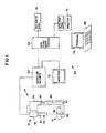
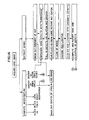
- Figure 1 is a block diagram illustrating lens inspection system 10; and generally system 10 comprises transport subsystem 12, illumination system 14, imaging subsystem 16, and image processing subsystem 20.
- transport subsystem 12 includes lens carrier 22 and support assembly 24 (shown in Figure 4); and illumination subsystem 14 includes housing 26, light source 30, and mirrors 32 and 34.
- imaging subsystem 16 includes camera 36, stop 40, and lens assembly 42. More specifically, with reference to Figure 8, the camera includes housing 44, pixel array 46, and shutter 50; and the lens assembly includes housing 52, a pair of lenses 54 and 56, and a plurality of baffles 60.
- image processing subsystem 20 includes preprocessor 62, main processor 64, and input means such as keyboard 66; and preferably subsystem 20 further includes memory unit 70, video monitor 72, keyboard terminal 74, and printer 76.
- transport subsystem 12 is provided to move a multitude of ophthalmic lenses along a predetermined path to move each of those lenses, one at a time, into a lens inspection position, and Figure 1 shows one such lens 80 in this lens inspection position.
- Illumination subsystem 14 is provided to generate a series of light pulses and to direct a respective one light pulse onto light path 82 and through each ophthalmic lens moving through the lens inspection position.
- Subsystem 16 generates a set of signals representing selected portions of the light pulses transmitted through the ophthalmic lens and then transmits these signals to processing subsystem 20.
- the image processing subsystem receives those signals from subsystem 16 and processes those signals according to a predetermined program to identify at least one condition of each of the lenses that is inspected; and in the preferred embodiment of subsystem 20 described below in detail, that subsystem determines whether each inspected lens is acceptable for consumer use.
- System 10 may be used to inspect a large variety of types and sizes of ophthalmic lenses.
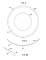
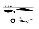
- the system is particularly well-suited for inspecting contact lenses, and Figures 2 and 3 illustrate, for example, contact lens 84 that may be inspected by system 10.
- Lens 84 has a generally hemispherical shape, including front and back surfaces 86 and 90; and the lens forms a central optical zone 84a and an outer zone 84b.
- the lens has a substantially uniform thickness; however, as particularly shown in Figure 3A, the thickness of the lens gradually decreases over the annulus 84C immediately adjacent the outside edge of the lens.
- Figure 4 illustrates transport subsystem 12 in greater detail; and as discussed above, this subsystem preferably includes lens carrier 22 and support assembly 24. More specifically, this support assembly includes translation table 92 and first and second stepper motors 94 and 96, and the translation table, in tum, includes base member 100 and frames 102 and 104.
- lens carrier 22 is provided to hold a multitude of the ophthalmic lenses, and Figures 5 and 6 show the lens carrier in greater detail.
- the lens carrier includes a rectangular base member 106 and an array of lens inspection cups 110 connected to the base member.
- each cup consists of a frusto-conical sidewall 110a and a hemi-spherically shaped bottom portion 110b integrally connected to and extending downward from the sidewall of the cup.
- the bottom portion of each cup preferably has a constant radius of curvature, approximately 10% larger than the radius of curvature of the ophthalmic lens 84 placed in the cup, and the diameter of the bottom portion 110b is greater than the diameter of the ophthalmic lens.
- the sidewall of each cup extends at a slope of about 20° with respect to the axis of the cup, and the thickness of each sidewall is preferably less than about 0.010 inches.
- the diameter of the top of each cup 110 is about 22 mm; and the depth of each cup is preferably greater than the diameter of the lens to be inspected, which, for contact lenses, is typically 20 mm.
- the lens carrier includes a 3 x 4 array of inspection cups.
- the inspection cups may be arranged in other configurations; and for instance, the cups may be arranged in a 3 x 3 array, a 3 x 8 array, a 4 x 8 array, a 3 x 10 array, or a 4 x 10 array.
- Cups 110, and preferably base member 106 are made of a substantially transparent material, such as polyvinyl chloride plastic. Moreover, preferably cups 110 and base member 106 are integrally molded together and are relatively thin, which reduces the cost and thus, as a practical matter, allows the carrier to be disposed after a single use. Disposing of the carrier after a single use substantially reduces or eliminates the formation of scratches in the cups, which are often made when lens inspection cups are reused. Since, as discussed below, a scratch on a cup may be interpreted as a flaw or defect in the lens inside the cup, the use of readily disposable lens carriers improves the accuracy of the lens inspection process.
- each cup 110 is partially filled with a fluid solution 112 such as, for example, a saline solution, and a respective one ophthalmic lens is placed at the bottom of each cup, fully submerged in the solution therein.
- a fluid solution 112 such as, for example, a saline solution
- a respective one ophthalmic lens is placed at the bottom of each cup, fully submerged in the solution therein.
- support assembly 24 is provided to support the lens carrier and to move the lens carrier so as to move each of the lenses therein, one at a time, into the lens inspection position.
- Support assembly 24 moves lens carrier 22 continuously along a predetermined path to move lenses 84 smoothly into and through that lens inspection position.
- the support assembly may be designed to move the lens carrier so that cups 110 of that carrier are moved through the lens inspection position, one row of cups at a time; and after each row of cups is passed through the lens inspection position, support assembly 24 moves carrier 22 to align another row of cups with the lens inspection position.
- frame 102 of translation table 92 is supported by base 100 for lateral movement thereon, to the right and to the left as viewed in Figure 4; frame 104 is supported by frame 102 for movement thereon, upward and downward as viewed in Figure 4; and lens carrier 22 is supported on frame 104 for movement therewith.
- Stepper motor 94 is mounted on base 100 and connected to frame 102 to move that frame across the base member, and stepper motor 96 is mounted on frame 102 and connected to frame 104 to move this latter frame.
- any suitable frames 102 and 104 and stepper motors 94 and 96 may be used in support assembly 24.
- other suitable support assemblies are known and may be used to move lens carrier 24 in the desired manner.
- subsystems 14 and 16 together, produce and then utilize an effect referred to as dark field illumination to inspect the ophthalmic lenses moving through the lens inspection position.
- an image is formed on pixel array 46 of features of the ophthalmic lens that scatter or reflect light transmitted through the lens.
- Dark field illumination may be used --and indeed is a highly effective procedure-- to detect flaws or irregularities in ophthalmic lenses because essentially all defects, as well as some normal features, of the ophthalmic lenses scatter light; and even very subtle, shallow defects, such as those referred to as puddles, can be readily detected by using a dark field illumination procedure.
- FIG. 7 shows an ophthalmic lens 114, a collimated light beam 116, a pair of lenses 120 and 122, an opaque stop 124, and a pixel array 126.
- Light beam 116 is transmitted through ophthalmic lens 114 and then is incident on imaging lens 120. If the illumination beam 116 were perfectly collimated when incident on lens 114, then that beam would be brought to a focus at the back focal point of lens 120.
- Stop 124 is located on the other side of imaging lens 120, at this back focal point thereof, and the size of the stop is selected to be slightly larger than that circle image formed by the illuminating beam 116 at the back focal point of lens 120.
- ophthalmic lens 114 is located at a position that is optically conjugate to the position of the pixel array 126; and thus, if any light is transmitted past stop 124, that light forms an image on the pixel array of the entity of ophthalmic lens 114 that scattered the light.
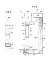
- Figure 8 shows the preferred apparatus for producing and then utilizing this dark field illumination effect in system 10; and in particular this figure shows the preferred illumination subsystem and imaging subsystem in greater detail.
- subsystem 14 includes housing or casing 26, light source 30, mirrors 32 and 34, diaphragm 130, power supply 132, control circuit 134, first and second adjustable support means 136 and 140, and exit window 142.
- subsystem 16 includes camera 36, stop 40, and lens assembly 42. More specifically, camera 36 includes housing 44, pixel array 46, and shutter 50; and lens assembly 42 includes housing 52, lenses 54 and 56, and baffles 60.
- Housing 26 of subsystem 14 provides a protective enclosure for other elements of this subsystem; and light source 30, mirrors 32 and 34, and diaphragm 130 are all secured in that housing. More specifically, housing 26 includes a main vertical leg 26a and top and bottom horizontal legs 26b and 26c, and light source 30 is positioned inside the main leg of the housing. Mirror 32 is secured in the intersection of legs 26a and 26c, mirror 34 is positioned adjacent the distal end of leg 26c, and diaphragm 130 is positioned inside leg 26c, between mirrors 32 and 34. Housing 26 also forms an opening 26d directly above mirror 34, and window 142 is secured in that opening. In use, light source 30 generates a multitude of light flashes or pulses and directs each of those pulses onto light path 82.
- Mirror 32 is located on this path and directs the light pulses through diaphragm 130 and onto mirror 34, which in turn directs the light pulses upwards, through window 142, through the lens inspection position, referenced at 144 in Figure 8, and toward or onto imaging subsystem 16.
- light source 30 is mounted on adjustable support means 136 that allows the specific direction of the light emitted from that light source to be adjusted
- mirror 34 is mounted on another adjustable support means 140 that allows both the specific direction and the specific position of the light reflected from that mirror to be adjusted.
- support means 136 includes a tilt stage that is secured to housing 26 and is pivotal about two mutually orthogonal horizontal axes.
- mirror support means 140 includes tilt stage 140a and translation stage 140b; and mirror 34 is mounted on the former stage, which in turn is mounted on the latter stage.
- Stage 140b is movable laterally, to the left and to the right as viewed in Figure 8, allowing the lateral position of mirror 34 to be adjusted; and stage 140a is pivotal about two mutually perpendicular horizontal axes, also allowing the specific angle of mirror 34 to be adjusted.
- Imaging subsystem 16 receives light pulses transmitted through the ophthalmic lenses located in the lens inspection position 144, and generates a series of signals representing selected portions of the light transmitted through those ophthalmic lenses. More particularly, pixel array 46 is disposed inside camera housing 44, directly behind shutter 50; and the pixel array is preferably comprised of a multitude of light sensors each of which is capable of generating a respective one electric current having a magnitude proportional to or representing the intensity of light incident on that sensor.
- Figure 9 is an enlarged view of a small portion of pixel array 46, and in particular, shows a multitude of individual light sensors of the pixel array.
- these light sensors, or pixels are arranged in a uniform grid of a given number of rows and columns, and for example, that grid may consist of one million pixels arranged in one thousand columns and one thousand rows.
- the pixels form a multitude of uniformly spaced rows and a multitude of uniformly spaced columns; and, except for those pixels along the very edge of the array, each pixel has eight immediate neighbors.
- pixel 146a has eight neighbors: pixel 146b located directly above, pixel 146c located directly below, pixels 146d and 146e located directly to the left and to the right respectively, and pixels 146f, 146g, 146h, and 146i located, respectively, above and to the right, above and to the left, below and to the right, and below and to the left.
- stop 40 and lenses 54 and 56 are located forward of shutter 50 and are coaxially aligned with each other and with pixel array 46 and the camera shutter.
- Stop 40 is positioned between lenses 54 and 56 and substantially at the back focal plane of lens 54, and lens 56 is positioned so that the pixel array is at the back focal plane of this lens 56.
- lenses 54 and 56 and stop 40 are mounted inside housing 52, which in tum is mounted on the front end of camera 36.
- baffles 60 which may comprise a series of ring-shaped members, are preferably mounted in and spaced along the length of housing 52 to help collimate the light travelling therethrough.
- the lens inspection position is located at a position that is optically conjugate to the position of pixel array 46, and thus any light that is transmitted past stop 40 forms an image on the pixel array of the entity of the ophthalmic lens that scattered that light.
- This dark field illumination technique is a very effective way to illuminate irregularities in ophthalmic lenses; and
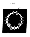
- Figure 10 shows the image formed on pixel array 46 by a beam of light transmitted through an ophthalmic lens, and in particular, through a contact lens 84 shown in Figures 2 and 3. Most of the light transmitted through the lens is blocked from the pixel array by step 40. However, due to the non-uniform thickness of annulus 84c of the lens, the light transmitted through this portion of the lens is deflected past stop 40 and is incident on pixel array 46, forming a picture of the annulus on that array. Other irregularities in lens 84 also produce illuminated areas on the pixel array. For instance, even subtle, shallow defects, such as puddles can be seen on the pixel array.
- the light source 30 may be a short-arc xenon flash lamp made by Hamamatsu. This particular flash lamp has a unique combination of arc stability and longevity, and the output of this flash lamp is rated plus or minus 2%, with a lifetime of 10 9 flashes.
- first imaging lens 54 is a 100 mm focal length achromatic lens that is diffraction-limited for objects within 2.5° of the optical axis of the lens, and the lens 54 is mounted in a black-anodized aluminum tube, with internal baffles 60 to eliminate degradation of contrast due to the reflection of light from the inside walls of the tube.
- the second lens 56 is a standard 50 mm focal length F-1.8 Nikon lens.
- the end of the barrel for the first lens 54 is cemented onto an ultraviolet haze filter, which is threaded into the housing of the 50 mm lens.
- Opaque stop 40 is a small plastic circle with a diameter of 0.100 inches, and includes an adhesive backing to secure the stop in place. Suitable stops are commercially available and are used as solder pad masks in manual layout of art work for printed circuit boards, and these stops are available in a large variety of sizes. The preferred size of stop 40 may vary depending on other parameters of system 10, and the selected size of the stop is preferably chosen to provide the best compromise between contrast, ease of alignment, and sensitivity to vibration.
- the camera used in the subsystem 16 that has been actually constructed is a high-resolution camera sold by Videk, and that accepts a standard Nikon mount lens.
- the F-1.8 50 mm Nikon lens 56 is first mounted on camera 36, and then the housing of lens 54 is threaded onto the lens 56.
- the effective field of view of this Videk camera is 13.8 x 13.8 mm, which is, for example, about 10-15% larger than the maximum contact lens size. It is desirable that the ophthalmic lens being inspected occupy as much of the field of view of camera 36 as possible in order to optimize the accuracy of the inspection.
- the inspection cups 110 of lens carrier 22 make maximum use of the resolution available in the camera.
- the preferred configurations of subsystems 14 and 16 have a number of advantages.
- Second, the size of the image of the arc on the stop 40 is substantially equal to the physical size of the arc, multiplied by the ratio of (i) the distance from lamp 30 to lens 54 to (ii) the distance from lens 54 to stop 40.
- the preferred configuration shown in Figure 8 also minimizes the arc image size, allowing the use of a smaller stop and consequently producing greater sensitivity.
- iris diaphragm 130 limits the cross-sectional area of light beam 82 and thus the area that is illuminated by that beam.
- diaphragm 130 is used to adjust the cross-sectional area or size of beam 82 so that the beam illuminates a circular area about only 10 to 15% larger than the diameter of the ophthalmic lens being inspected.
- Limiting the size of the illumination beam 82 improves the contrast between the image produced on the pixel array and the rest of that array; and in particular, limiting the size of beam 82 eliminates or substantially reduces the amount of light that scatters from artifacts of the lens inspection cup. This scattered light might appear as background light on pixel array 46, reducing the contrast between the image of interest on the pixel array and the rest of that array.
- the magnification factor of the system that is, the ratio of the size of the image of the ophthalmic lens on the pixel array 46 to the actual size of that ophthalmic lens-- is approximately equal to the ratio of the focal length of the second lens 56 to the focal length of the first lens 54.
- the actual magnification factor also depends upon the distance between the lenses 54 and 56 and the distance of the ophthalmic lens being inspected from the first imaging lens 54.
- tilt stage 140a and translation stage 140b allow the center of the output beam reflected off of mirror 34 to be adjusted to coincide with the axis of the imaging optical subsystem 16.
- imaging subsystem 16 includes two lenses 54 and 56, separated by approximately the focal length of the first lens 54.
- the use of two lenses is not necessary; however, this is preferred because the use of two lenses provides for a greater control over various parameters of subsystems 14 and 16, and for example, it decouples the separation between the back focal plane and the image plane from the magnification of the subsystems.
- Figures 11A, 11B, and 11C illustrate alternate optical configurations, generally referenced at 152, 154, and 156 respectively, that may be employed in system 10 for directing light beam 82 through the lens inspection position and the ophthalmic lens held in that position, and onto stop 40 and pixel array 46.
- Configuration 152 includes only one lens 160, which simultaneously images light beam 82 onto stop 40 and images the lens being inspected onto pixel array 46. More specifically, the optical configuration shown in Figure 11A includes mirror 162, imaging lens 160 and stop 40; and the Figure also shows a lens holder, schematically represented at 164, an ophthalmic lens 166 to be inspected and pixel array 46. With this configuration, light beam 82 or pulses from light source 30 is directed to mirror 162, which in turn directs the light through lens 166 and onto imaging lens 160.
- Figure 11A may be the preferred configuration if the CCD screen of camera 36 is larger than the CCD screen of the above-mentioned high-resolution Vidik camera.
- this configuration includes mirror 170, lenses 172 and 174 and stop 40; and Figure 11B also shows lens holder 164, ophthalmic lens 166 and pixel array 46.
- light beam 82 from light source 30 is directed onto mirror 170, and this mirror directs the light beam to lens 172.
- Lens 172 directs the light through ophthalmic lens 166, and most of the light transmitted through lens 166 is focused on stop 40.
- lens 166 deflect light away from stop 40, however; and this deflected light is incident on lens 174, which focuses that light onto pixel array 46, producing thereon an image of the feature of lens 174 that deflected the light past stop 40.
- An advantage of the lens arrangement of Figure 11 B is that the actions of the two lenses 172 and 174 are completely independent.
- Optical configuration 156 shown in Figure 11C is very similar to the optical configuration shown in Figure B; however configuration 156 does not include mirror 32 or diaphragm 130. More particularly, configuration 156 includes mirror 176, lenses 180 and 182 and stop 40; and Figure 11C also shows lens holder 164, ophthalmic lens 166 and pixel array 46.
- light beam 82 from light source 30 is directed onto mirror 176, which directs the light through lens 166 and onto first first lens 180. Most of the light directed to lens 180 is focused onto stop 40; however some features of lens 166 deflects light sufficiently so that this light is transmitted past stop 40 and onto second lens 182, and this lens 182 focuses this light onto pixel array 46.
- lens 180 images the light source onto stop independent of lens 182. Both lenses 180 and 182, however, are involved in imaging any defects in lens 166 onto pixel array 46.
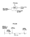
- system 10 also preferably includes a control subsystem to synchronize the operation of illumination subsystem 14 and imaging subsystem 16 with the operation of transport subsystem 12; and, in particular, to actuate the light source 30 to generate a light pulse, and to open camera shutter 50, when a lens is in the lens inspection position 144.
- the preferred control subsystem is illustrated schematically in Figure 12A. With this preferred control subsystem, transport subsystem 12 generates an electric signal each time one of the lens inspection cups is in the lens inspection position. This signal may be generated, for example, by stepper motor 94, or by another drive means for translation table 92, or by a limit switch that is engaged each time one of the lens inspection cups reaches the lens inspection position.
- this signal is transmitted to camera shutter 50 to open that shutter, and also transmitted to a delay circuit 184 that delays the electric signal for a short period, to allow the camera shutter to open completely, and after this short delay, this electric signal is then transmitted to a lamp driver 134 that then actuates light source 30.
- the transport subsystem when an ophthalmic lens is in the lens inspection position, the transport subsystem generates and transmits a 24 volt pulse both to camera 36 and to delay circuit 184.
- the camera shutter opens in response to the leading edge of this pulse, and takes about 9 milliseconds to open completely.
- the delay circuit delays passage of the signal to lamp driver 134 for about 15 milliseconds; and after this delay, this trigger pulse is transmitted to the lamp driver.
- the leading edge of this trigger pulse actuates an SCR, which ignites the flash lamp 30. At this point of ignition, the lamp becomes electrically conductive, and a previously charged capacitor is discharged across the lamp. The capacitance and voltage to which that capacitor were charged determine the total light energy emitted by the lamp and the duration of the light pulse. Meanwhile, an interface circuit holds the camera shutter open for about 30 milliseconds and then closes the shutter.
- the use of a camera shutter in the above-described manner avoids or substantially reduces the integration of ambient light in pixel array 46 between lens inspections.
- the high voltage power supply, lamp driver electronics and storage capacitor are mounted in the housing structure 26 that contains the illumination optics.
- the light from lamp 30 is sufficient to allow the capture of an image on pixel array 46 in such a short period of time that it is not necessary to stop the ophthalmic lens being inspected.
- the transport subsystem 12 is designed to move an array of ophthalmic lenses continuously under the imaging subsystem 16. This continuous, smooth movement of the ophthalmic lens array is advantageous because it reduces or eliminates the development of ripples or other disturbances of the top of the solution 112 in cups 110, which might interfere with the imaging process.
- transport subsystem 12, illumination subsystem 14, and imaging subsystem 16 may be achieved in other ways.
- light source 30 may be activated and shutter 50 may be opened at predetermined time intervals that are chosen to coincide with the positioning of a lens in the lens inspection position 144.
- the illumination, imaging, and transport subsystems may be enclosed within a housing (not shown) to minimize the effects of airborne debris on the illumination and imaging processes.
- That housing may be provided with transparent front doors or with front doors having transparent windows to provide access to and to allow observation of the interior of the housing, and the transparent portions of those front doors may be tinted to minimize the effects of ambient room light on the illumination and imaging processes.
- FIG. 13 is a block diagram illustrating image processing subsystem 20.
- the electric signals from the pixel array are conducted, in a combination of a series and parallel formats, to pre-processor 62.
- These electric signals being transmitted to pre-processor 62 may be identified in any suitable way with the specific pixels that generated the signals.
- the signals from the pixels of camera 36 may be transmitted to pre-processor 62 in a given, timed sequence, and a clock signal may also be transmitted to the preprocessor from the camera to identify the start, or selected intervals, of that sequence.
- each signal transmitted to processor 62 may be provided with a header or another data tag identifying the particular pixel that generated the signal.
- Unit 62 converts each electric current signal from each pixel of array 46 into a respective one digital data value, I o , and stores that data value at a memory location having an address associated with the address of the pixel that generated the electric signal.
- These data values are available to processor 64 and may be transmitted thereto via bus lines 186.
- a plurality of additional sets of data values I 1 ...I n are generated, with each data set having a respective one data value associated with each pixel of array 46, and pre-processor 62 may include a multitude of memory sections, or boards, each one of which is used to store a respective one set of these data values.
- Processor 64 is connected to preprocessor 62 via bus lines 186 to obtain data values from and to transmit data values to that preprocessor. As explained in greater detail below, processor 64 is programmed to process and analyze the data values stored in the preprocessor to identify at least one condition or parameter of each lens inspected by system 10, and for example, to indicate whether each lens is acceptable for consumer use.
- Memory disk 70 is connected to processor 64 to receive and to hold data values on a permanent or semi-permanent basis.
- memory disk 70 may be provided with various look-up tables used by processor 64, and the memory disk may be used to store data relating to or obtained in the lens inspection process.
- memory disk 70 may be used to keep track of the total number of lenses inspected during a given day or time period, and to keep track of the total number, type, and size of any defects found in any given sample or group of lenses.
- Keyboard 66 is connected to processor 64 to allow operator input thereto, and keyboard terminal 74 is used to display visually data or messages being input into the processor.
- Monitor 72 is connected to preprocessor 62 and is provided to produce video images from the data values stored in the preprocessor. For example, the I o data values may be transmitted to monitor 72 to produce thereon an image of the real image produced on pixel array 46. Others of the sets of data values I 1 ...I n may be transmitted to monitor 72 to produce refined or processed images of that real image.
- Printer 76 is connected to processor 64, via serial-parallel converter 190, to provide a visual, permanent record of selected data values transmitted to the printer from processor 64.
- subsystem 20 may be provided with other or additional input and output devices to allow an operator or analyst to interact with processor 64, preprocessor 62, and memory unit 70.
- processor 64 is a high-speed digital computer
- monitor 72 is a high resolution color monitor
- preprocessor 62 may be an assembly of Datacube signal processing boards, and processor 64 may be a Sun 3/140 work station.
- This output current for each pixel is converted to a digital data value that is stored in an address in preprocessor memory associated with the pixel.
- These digital data values referred to as the I o values, are processed, as described below, to determine whether the lens passing beneath the camera 36 includes one or more of a selected group of features; and in particular, to determine whether that lens contains any feature that may be considered as a flaw or defect that renders the lens unsuitable for consumer use.
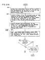
- Figure 14 shows the major components of a preferred image processing procedure to identify any defects in the type of lens 84 shown in Figures 2 and 3.
- a procedure referred to as decentration to determine if the inside and outside circumferential edges of annulus 84c of the lens are properly centered relative to each other, and this decentration test involves fitting first and second circles to the inner and outer edges of the annulus produced on the pixel array. After this, the actual edges of the annulus are found or extracted.
- a first masking procedure is used to reduce or eliminate data associated with light refracted or deflected by the periphery of the lens inspection cup, and any edge defects are highlighted by a procedure referred to as the rubber band algorithm.
- any defects are further emphasized by procedures referred to as fill-in and clean-up and by a second mask procedure that eliminates data associated with certain pixels near the center of the annulus image.
- a search is made to determine if in fact any defects exist.
- the pixels of array 46 are searched --or, more precisely, data values associated with those pixels are searched-- to identify line segments, or runlengths, of pixels that may be part of a defect, and those runlengths are then clustered to identify defect candidates. Then, the sizes and locations of these defect candidates are analyzed to determine if they are actual defects that make the lens unsuitable for consumer use.
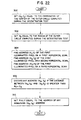
- the decentration test is used to determine whether the inside and outside circumferential edges of annulus 84c of the lens passing beneath the camera are concentric.
- this is done by making a multitude of scans 202 across the pixel array 46 --or, more precisely, by studying data values at addresses in the preprocessor memory that correspond to the addresses of pixels in selected line segment on array 46-- to determine whether the outside and inside edges 150a and 150b of annulus 150 are concentric.
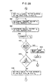
- FIGS 16a and 16b illustrate the decentration test or routine R 1 .
- the first step 204 in this routine is referred to as a thresholding subroutine; and the purpose of this routine is to associate each pixel with a new intensity value I 1 equal to either the maximum or minimum illumination values, T max or T min , depending on whether the original illumination value I o of the pixel is, respectively, above or below a given threshold value T t .
- each pixel having an original illumination value I o greater than 127 may be provided with a new illumination value I 1 of 255, and each pixel having an original illumination value of 127 or less may be provided with a new illumination value I 1 of zero.
- the next step 206 in the decentration test is to set the number, locations, and sizes of the scans 202 used in this test, and this is done by providing the processor 64 with the address of the starting pixel and the length and direction of each scan. These parameters are chosen so that, unless the lens is badly decentered, each of a multitude of the scans cross both edges of annulus 150.
- processor 64 or memory disc 70 is provided with a semi-permanent record of these starting addresses, directions and scan lengths. This record is used during the inspection of each lens of a given nominal type or size, and this semi-permanent record may be changed when lenses of a different nominal type or size are inspected.
- the selected scans are made across the pixel array or display 46. Unless a lens is badly decentered, most of these scans will cross an illuminated portion of that display.
- the addresses of the first and last pixels of the line segment crossing that illuminated portion and the length of that line segment are recorded in a file f 1 .
- Subroutines for detecting the first and last pixels in a run length, for obtaining the addresses of those pixels, and for determining the length of each run length are well-known by those of ordinary skill in the art, and any such suitable routines may be employed in the decentration test.
- the length of each of these run lengths is compared to a predetermined value, and the data --that is, the addresses of the first and last pixel in the run length and the length of the run length-- associated with each run length less than that predetermined value, are discarded.
- This discarding is done to eliminate, or at least to reduce the amount of, data caused by noise on the pixel array 46 --that is, undesirable light that is incident on the pixel array.
- noise which may be due to background light or to light that is deflected off the desired light path by dust or other particles, may produce illuminated areas on the pixel array. In the vast majority of instances, each of these illuminated areas consists of only one or a small group of adjacent pixels.
- step 210 If one of the above-mentioned scans made during step 210 crosses such an illuminated area, then the processor records the addresses of the first and last pixel of and the length of the run length across that illuminated area. This illuminated area and the associated data, however, are not related to annulus 162 or to the edges thereof, and thus step 212 is provided to eliminate this data.
- the next step 214 in the decentration test is to identify each of the remaining pixel addresses as being on the outer edge or the inner edge of the annulus, and any suitable subroutine may be employed to do this. For instance, the addresses of the first and last pixel of each run length may be compared to each other; and the pixel closer to the center of the entire pixel array 46 may be considered as being on the inner edge of annulus 162, while the pixel further away from the center of the pixel array may be considered as being on the outer edge of the annulus.
- the scans may be separated into two groups such that for each scan in the first group, if an illuminated run length is found during the scan, the first and last pixels in the run length are on the outer and inner edges, respectively, of the annulus; and for each scan in the second group, if an illuminated run length is found during the scan, the first and last pixels in the run length are on the inner and outer edges, respectively, of the annulus.
- each pixel is determined to be on the inside or the outside edge of annulus 162
- the number of pixels that have been found on each edge is counted. If either of these numbers is less than three, then at step 220, the lens is rejected on the basis that the lens is badly decentered.
- a subroutine is invoked, first, to fit a first circle onto the pixels that were found on the outside edge of the annulus, second, to fit a second circle onto the pixels that were found on the inside edge of the annulus, and third to determine the centers and radii of these two circles.
- Numerous subroutines are well-known for fitting a circle onto three or more points and to calculate the center and radius of that circle, and any such subroutine may be used in the decentration test at step 222.
- the distance d between these two centers is determined at step 224. This distance is then compared, at step 226, to a first value d 1 ; and if the distance is greater than d 1 , then the lens is rejected at step 230 as being badly decentered. If the distance d is less than d 1 , then, at step 232, that distance d is compared to d 2 , which is the maximum acceptable distance between the centers of the inner and outer edges of annulus 150.
- the lens is rejected, at step 234, as being decentered; however, if the distance d is equal to or less than d 2 , then the lens passes the decentration test, as indicated by step 236.
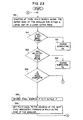
- processor 64 then initiates a process or routine R 2 , referred to as edge detector, to produce a set of illumination values that, in turn, may be used to identify the pixels on the edges of annulus 150. Typically, these edges are not perfect circles and thus are different from the fitted circles found during the decentration test.
- This new set of illumination values is obtained through a series of morphological operations or changes in the original intensity values assigned to or associated with each pixel of array 46. These morphological changes are pictorially illustrated in Figures 17a through 17i, and shown in the form of a flow chart in Figure 18.
- Figure 17a shows an image of annulus 150 on pixel array 46; and Figure 17b shows an enlarged view of a portion of that annulus, and also shows a short line segment 240, or scan, across that annulus portion and the adjacent areas of the pixel array.
- Figure 17c illustrates the intensity values I 1 of the pixels in that scan 240; and as represented therein, the pixels in the dark areas of Figure 17b have a lower or zero I 1 value, and the pixels in the light areas of Figure 17b have a higher I 1 value, such as T max .
- a new value I 2 is calculated for each pixel; and, in particular, the I 2 value for each pixel is set equal to the average of the I 1 values of that pixel and its eight immediately adjacent pixel neighbors.
- the difference between the I 1 and the I 2 values for the pixels in array 46 is that the latter values change more gradually between the pixels having the lowest I 2 value (which generally are those pixels in the dark areas of the pixel array), and the pixels having the highest I 2 value (which generally are those pixels in the light areas of array 46). This difference may be best understood by comparing Figures 17c and 17d.
- a further value I 3 is determined for each pixel; and specifically, the I 3 value for each pixel is set equal to the minimum I 2 value of that pixel and its eight immediately adjacent pixel neighbors.
- the I 3 values may vary across the scan 240 in a manner very similar to the way in which the I 2 values vary across that pixel scan.
- the principle difference between the manner in which the I 2 and I 3 values of the pixels vary across the pixel array is that the band of pixels having the highest I 3 value is slightly narrower than the band of pixels having the highest I 2 values.
- the next step 246 in the edge detector process is to determine a still further value I 4 for each pixel according to the equation I 4 - I 2 - I 3 .
- I 4 the pixels in the scan 240 have I 4 values of zero; however, the pixels on and radially immediately inside the two edges of annulus 162 have positive I 4 values.
- an I 5 value is determined for each pixel; and more specifically, the I 5 value of each pixel is set equal to the maximum I 2 value of the pixel and its eight immediately adjacent pixel neighbors. For most of the pixels on the pixel array 46, the I 5 value of the pixel is the same as the I 2 value of the pixel.
- the I 5 values of the pixel are greater than the I 2 values of the pixel, and the band of pixels having the highest I 5 value is slightly wider than the band of pixels having the highest I 2 value.
- I 6 I 5 - I 2 .
- an I 7 value is assigned to each pixel; and more specifically, the I 7 value of each pixel is set equal to the smaller of the I 4 and I 6 values for the pixel.
- most of the pixels on the pixel array have an I 7 value of zero; however, the pixels directly on and immediately adjacent the two edges of annulus 150 have positive I 7 values. In this way, the I 7 values of the pixels identify the pixels that are on the edges of annulus.
- a thresholding subroutine may then be invoked at step 256 to sharpen the distinction between the pixels on the edges of annulus 150 and the other pixels in display 46.
- each pixel may be assigned a still further value I 8 equal to either the maximum illumination intensity value T max or the minimum illumination intensity value T min depending on whether the I 7 value of the pixel is, respectively, above or below a given threshold value such as T t .
- each pixel having an I 7 value greater than 32 may be provided with an I 8 value equal to 255, and each pixel having an I 7 value of 32 or less may be provided with an I 8 value of zero.
- Figure 17j shows each pixel of array 46 illuminated at an intensity equal to its I 8 value.
- each set of pixel values is stored in a respective one memory register in preprocessor 62 --that is, for example, the I 0 values are all stored in a first register, the I 1 values are all stored in a second register, and the I 2 values are all stored in a third register. It is not necessary to store all of the I 1 -I 8 values during the entire processing period for each lens, however; and, for instance, during each processing period, the I 3 values may be discarded after the I 4 values are calculated, and the I 5 values may be discarded after the I 6 values are determined.
- I 2 -I 8 values it is not necessary to calculate I 2 -I 8 values for all the pixels in the array 46.
- the annulus of the lens will appear in a relatively well-defined region or area of the pixel array 46, and it is only necessary to determine the I 2 -I 8 values for the pixels in that region or area.
- the lens inspection system invokes a masking routine to produce a set of pixel illumination values that is free of the effect produced by the edge of the lens inspection cup used to hold the lens.
- a masking routine to produce a set of pixel illumination values that is free of the effect produced by the edge of the lens inspection cup used to hold the lens.
- This edge image is not related to the lens itself, and thus any data associated with that cup edge image are unnecessary and undesirable to the processing of the data associated with the lens image itself; and a masking routine is invoked to eliminate the cup edge image from pixel array 46, or more precisely, to produce a set of pixel illumination values that is free of the pixel data associated with the above-mentioned cup edge image 260.
- Figure 20 is a flow chart illustrating a preferred masking routine R 3 .
- the first step 262 in this routine is to determine whether, at steps 216 or 226 of the decentration test, at least three pixels had been found on the outside edge of annulus 162 or if the ophthalmic lens was found to be badly decentered. If the lens had been found to be badly decentered at either of these two steps of the decentration test, then masking routine R 3 itself terminates at step 262.
- routine R 3 does not terminate at step 262
- the routine proceeds to step 264, which is to obtain the coordinates of the center of the circle that had been fitted to the outside edge 150a of annulus 150 during the decentration test. These coordinates had been determined and then stored in memory, either in the memory of processor 64 or in memory disc 70, during the decentration test, and thus, these coordinates can be obtained by simply retrieving them from the memory.
- a mask subroutine is invoked at step 266. With reference now to Figure 19b, this subroutine, in effect, superimposes over pixel array 46, a circular mask 270 centered on the above-mentioned center coordinates, and having a diameter slightly larger than the diameter of the circle fitted to the outer edge of annulus 150.
- the masking subroutine then assigns an I 9 value to each pixel based on whether the pixel is inside or outside this mask. In particular, for each pixel outside that mask, the masking subroutine assigns the pixel an I 9 value of zero; and for each pixel inside the mask, the masking subroutine assigns the pixel an I 9 value equal to the I 8 value for the pixel.
- step 266 the coordinates (x 0 , y 0 ) of the above-mentioned center point and a radius value r 1 , which is selected to be slightly larger than the radius of the circle fitted to the outside edge of annulus 150, are transmitted to the mask subroutine. Then this subroutine forms a file f 2 of the addresses of all of the pixels in array 46 that are within the distance r 1 of that center point (x o , y o ). Then, at step 272, the address of each pixel in array 46 is checked to determine if it is in that file.
- the I 9 value of the pixel is set equal to the I 8 value of the pixel; however, if the pixel address is not in that file, then at step 276 the I 9 value of the pixel is set to zero.
- Figure 19c shows the pixels of array 46 illuminated at an intensity equal to their respective I 9 values.
- processor 64 initiates a further procedure, referred to as the rubber band algorithm.
- This algorithm generally, involves analyzing and processing data values for or relating to the pixels in and immediately adjacent to the annulus edge 150a, and.
- Figures 21a and 21 b show a flow chart that generally illustrates the rubber band algorithm.
- the first step 280 in this algorithm is to obtain the center coordinates and the radius of the circle fitted to the outer edge 150a of the lens in the decentration test. As discussed above, these values had been determined and then stored in memory during the decentration test, and these values can be obtained by retrieving them from that memory.
- the next step 282 in the rubber band algorithm is to locate a pixel on the outer edge 150a of annulus 150 by searching inward from the left edge of pixel array 46, until an illuminated pixel is found. It is possible that the first illuminated pixel found during a given search might not be on the edge of the image of the lens, but might be somewhere else and illuminated because of background noise. Hence, preferably, a multitude of scans or searches are conducted at step 282 to find a multitude of illuminated pixels, and the locations of these pixels are then analyzed or compared to each other to help ensure that a pixel is found on the edge of the lens image.
- the rubber band algorithm proceeds to step 284; and at this step this algorithm, in effect, starts at this first pixel and traces all the way around the edge of the lens image, eventually returning to that first pixel.
- the algorithm records in file f 3 the addresses of most or all of the pixels on the outside edge of the lens image; and the algorithm also identifies larger gaps in the lens edge, the lengths of those gaps, and larger extra pieces on the lens edge.
- the algorithm records in file f 4 the addresses of the pixels that are the end points of selected lines, discussed in greater detail below, that in effect are drawn across any larger gaps in the lens edge and across and on either side of any larger extra pieces on that edge.
- the rubber band algorithm determines, at step 290, if any gap that might have been found is large enough to cause the lens to be rejected. If such a gap is found, the lens is rejected, and at step 292, the printer 76 prints the message that the lens has a bad edge.
- the rubber band algorithm proceeds to make a second pass or trace around the edge of the lens image.
- the algorithm identifies shallow features, such as smaller gaps and smaller extra pieces, extending either radially inward or outward along the outside edge of the lens, and the algorithm tests each such detected feature to determine if the lens should be rejected because of it.
- this is done by computing, for each of at least selected pixels on the outside edge of the lens, the dot product of two vectors, referred to as the radial vector and the edge vector, through that pixel.
- the radial vector through a pixel is that vector that also extends through the center point of the circle fitted to the outside edge 150a of annulus 150.
- the edge vector through a pixel is the vector that extends through that pixel and a second pixel on the outside edge of annulus 150, a given number of pixels rearward, or counterclockwise, from the former pixel along the outside edge 150a of annulus 150.
- the dot product of the two above-identified vectors will be substantially zero, because the radial and edge vectors through that pixel are substantially perpendicular.
- the dot product of the edge and radial vectors through that pixel will not be zero, because these two vectors are not perpendicular. If any calculated dot product is greater than a given value, then the lens is considered as not suitable for consumer use and may be rejected.
- the rubber band algorithm makes a third pass around the edge of the lens image, as represented by step 296 in Figure 21B.
- This third pass does not include any test to determine if the lens should be rejected, but instead involves processing or preparing data for subsequent tests.
- this third pass is made to produce a set of data values that is free of data associated with any defects in the lens that are just inside the outer edge 150a of annulus 150. This set of data values is subsequently subtracted from a set of data values containing data associated with those defects, to produce thereby a set of data values having only the data associated with those flaws.
- the rubber band algorithm determines the average radial thickness of the outside edge 150a of the annulus 150; and then the algorithm sets to zero the I 9 values of all the pixels that are just inside that outside edge of the annulus. For example, if the outside edge of the annulus has an average thickness of six pixels, then the rubber band algorithm may set to zero the I 9 values of all of the pixels that are between 7 and 27 pixels radially inward of the outside edge of the annulus.
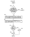
- Figures 22-32 illustrate the rubber band algorithm in more detail. More specifically, Figure 22 illustrates one suitable subroutine S 1 for locating a first pixel, P(x, y), on the outer edge 150a of the annulus 150.
- S 1 for locating a first pixel, P(x, y), on the outer edge 150a of the annulus 150.
- (x 0 , y 0 ) is set equal to the coordinates of the center of the circle that was fitted to the outer edge of the annulus during the decentration test; and at step 302, r 0 is set equal to the radius of that outer fitted circle.
- a multitude of horizontal scans are made across the pixel array 46, starting at, or about at, the center of the left edge of the array.
- processor 64 studies data values I 9 at addresses in the preprocessor memory that correspond to the addresses of pixels in selected horizontal line segments on the pixel array. During each of these scans, the processor 64 checks the I 9 value of each pixel in a given horizontal row of pixels, and identifies the first pixel in that row that has an I 9 value above a given value; and preferably, a multitude of such scans are made, resulting in a multitude of identified pixels.
- subroutine, S 1 identifies and discards the addresses of any such pixels.
- the subroutine first, determines the distance between each of the pixels identified in the scans and the center (x 0 , y 0 ) of the outer circle fitted to the outside edge of the lens image during the decentration test; and second, compares each determined distance to r 0 , which had been set equal to the radius of that fitted outer circle. If the distance between a particular pixel and the center of that fitted circle exceeds r 0 by more than a given distance, d 3 , then that pixel is considered as not being on or immediately adjacent the edge of annulus 150, and the address of that pixel is discarded.
- any remaining pixel address may be selected as pixel P(x, y), and then the first pass around the edge of the lens image is begun.
- Figure 23 illustrates in greater detail how this first pass is made, and in particular, shows Routine R 4 for making this pass.
- the algorithm searches forward, or clockwise, along the outer edge of the annulus 150 for either a large gap in that edge, or a large extra piece on that edge, as represented by steps 314 and 320. Any suitable subroutine or procedure may be used to search along the edge.
- the processor may check the three or the five closest pixels in the row above or below the given pixel or in the column to the right or to the left of the given pixel, depending on the quadrant or sector of display 46 in which the given pixel is located, to identify the next pixel on the lens edge. From this next pixel, the processor may use this same procedure to identify the still next pixel on the lens edge.
- the processor may determine the distance, r, between that pixel and the center point (x o , y o ) of the circle fitted to the outside edge of the lens. The processor may conclude that a large gap has been found when, for each of a given number of consecutive pixels on the lens edge, r is smaller than r o by more than a given amount d g (that is, r o -r>d g ).
- the processor may conclude that a large extra piece has been found when, for each of a given number of consecutive pixels on the lens edge, r is greater than r o by more than a given amount d ep (that is, r-r o >d ep ).
- routine R 4 moves on to step 324.
- routine R 4 tests to determine if the first pass around the edge of annulus 150 is complete, and any suitable specific procedure or subroutine may be used to do this. For instance, as mentioned above, as the trace is made around the image of the lens edge, a file f 3 is made of the addresses of the pixels that have been found on that edge. At step 324, that file may be checked to determine if the address of the current edge pixel being considered is already on the file. If the pixel address is already on the file, then the first pass around the image of the lens edge is considered to be complete, while the pass is considered as not complete if this current pixel address is not already on file f 3 .
- step 330 the next pixel on the lens edge is found and P(x, y) is set equal to the address of this next pixel, and the routine R 4 then returns to step 312.
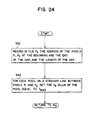
- Figure 24 is a flow chart outlining subroutine S 2 , which is invoked each time a gap is found on the outside edge of annulus 150.
- the first step 332 in this subroutine is to identify and record in a file f 4 the address of the pixels at the beginning and the end of the gap and the distance between these two end pixels. These two pixels are shown at P 1 and P 2 respectively in Figure 25A.
- the end of the gap may be found by searching across the gap, along the pixels on the circle fitted to the outside edge of the lens in the decentration test, and searching radially inwardly and outwardly for a given number of pixels from that portion of the fitted circle, until the lens edge is found --that is, until illuminated pixels, or more precisely, pixels having high I 9 values are found.
- the gap may be considered as having come to an end once a series of consecutive pixels is found that are all within a certain distance of that fitted circle; and in particular, when for each pixel in that series, r o -r is less than d g .
- the last pixel on the lens edge before that series of consecutive pixels may be considered as the pixel at the end of the gap.
- the I 9 values of the pixels on the line between pixels P 1 and P 2 --the line segment L 1 in Figure 25b-- are set equal to the maximum illumination intensity value, and then the subroutine returns to routine R 4 .
- Figure 26 shows a flow chart illustrating subroutine S 3 , which is invoked at step 322 of routine R 4 when an extra piece 350 is found on the edge of annulus 150.
- the first few steps in routine S 3 are done, in effect, to draw various bridge lines relating to the extra piece.
- the subroutine identifies pixels P 3 and P 4 , shown in Figure 25b, on the edge of the annulus 150 at the start and at the end of the extra piece 350; and then, at step 354, the I 9 value of each pixel on a line segment L 2 , shown in Figure 25c, between pixels P 3 and P 4 , is set to T max .
- the subroutine identifies the address of a pixel P 5 that is on the edge of the annulus 150 a given number of pixels rearward, or counterclockwise, of the start of the extra piece 350; and at step 360, the pixel P 6 on the edge of the extra piece that is a given distance d 4 from pixel P 5 is found.
- the I 9 value of each pixel on a line L 3 between pixels P 5 and P 6 is set to T max .
- the subroutine identifies the address of another pixel P 7 that is on the edge of the annulus 150 a given number of pixels forward, or clockwise, of the end of the extra piece; and then, at step 366, the subroutine identifies the pixel P 8 on the edge of the extra piece that is a given distance d 5 from pixel P 8 .
- the I 9 value of each pixel on the line L 4 shown in Figure 25e, between pixels P 7 and P 8 is also set to T max . After the appropriate bridge lines are drawn, the subroutine returns to routine R 4 .
- subroutine R 5 is invoked. This routine, which is illustrated in Figure 27, is used to determine if any of the gaps, which may have been found during the first pass around the image of the lens edge, is wide enough to make the lens unsuitable for consumer wear.
- the first step 376 in routine R 5 is to determine if any gaps were in fact found during the first pass around the lens edge. If no gaps were found, routine R 5 itself is terminated and the rubber band algorithm proceeds to routine R 6 . However, if any gaps were found during the first pass around the lens edge, routine R 5 proceeds to step 380.
- each gap width is compared, one at a time, to a given value d 6 ; and if any gap width is greater than that value d 5 , then the lens is considered to be unsuitable for consumer use, and the lens is rejected at step 382. If all of the gap widths are less than d 5 , however, then routine R 5 terminates, and the rubber band algorithm proceeds to routine R 6 , which performs the second pass or trace around the image of the lens edge.
- Routine R 6 is illustrated in Figure 28. As previously mentioned, this routine primarily searches for shallow gaps in the lens edge and small extra pieces on the lens edge that were not identified as gaps or extra pieces in routine R 4 , which was the first pass around the lens edge. In particular, at step 384, the address of pixel P (x, y) is set equal to the address of the first pixel in file f 3 . Then, at steps 386, 390, and 392, two vectors V 1 and V 2 , referred to as edge and radial vectors respectively, are identified and the dot product of these two vectors is calculated.
- the first vector V 1 is the vector through pixel P(x, y) and a second pixel on the lens edge, a given number of pixels rearward or counterclockwise of pixel P(x, y) along that lens edge
- the second vector V 2 is the radial vector of the annulus 150 that extends through pixel P(x, y). The slopes of these two vectors and their dot product can be easily determined from the addresses of the pixels through which the vectors extend.
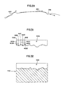
- edge vector V 1 through the pixel is substantially tangent to the lens edge, as shown at 394 in Figure 29. Also, this vector V 1 is substantially perpendicular to the radial vector V 2 through that pixel, and the dot product of these two vectors V 1 and V 2 is substantially zero.
- edge vector V 1 and the radial vector V 2 through pixel P(x, y) are not normally perpendicular, and the dot product of these two vectors will normally not be zero.
- the dot product of these two vectors V 1 and V 2 is compared, at step 402, to a given value d 7 . If that dot product is equal to or greater than that given value --which indicates that an appreciable gap or extra piece is present in the area of pixel P(x, y)-- then the lens is considered unacceptable for consumer use and is rejected at step 404, and the entire routine R 6 terminates. If at step 402, the calculated dot product is less than d 7 --which indicates that in the area of pixel P(x, y), any departure of the lens edge from a perfect circle is within an acceptable limit-- then routine R 6 moves on to step 406. At this step, the routine tests to determine if this second pass or trace around the image of the lens edge is complete.
- step 406 the address of pixel P(x, y) is set equal to the address of the next pixel on file f 3 , and then the routine returns to step 386.
- Steps 386 through 408 are repeated until either the lens is rejected or, for each pixel on file f 3 , the associated dot product of the two vectors V 1 and V 2 through that pixel has been calculated and found to be less than d 7 , at which time the rubber band algorithm proceeds to routine R 7 , which performs the third pass or trace around the lens edge.
- the above-mentioned dot product is not calculated for all the pixels on the lens edge, and in particular, that product is not calculated for the pixels that are on the edges of gaps or extra pieces that were found during the first trace around the lens edge. It is not necessary to calculate this dot product for these gap and extra piece pixels since it is already known that the pixels are on either a gap or an extra piece, and an appreciable amount of processing time may be saved by not determining the V 1 and V 2 vectors through those pixels and the dot product of those two vectors.
- routine R 7 which performs the third pass or trace around the lens edge.
- the purpose of this third pass is, in effect, to produce a new set of data values I 10 that are free of any data associated with any flaws in the lens that are just inside the outside edge of the lens.
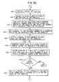
- Figure 30 shows routine R 7 in greater detail; and this routine, generally, is comprised of three parts. In the first part, the I 10 value for each pixel is set equal to the I 9 value for the pixel; in the second part, an average edge thickness value, N, is calculated for the outside edge 164 of annulus 162; and in the third part, the I 10 values of the pixels in a given range further inside of that average edge thickness are set to zero.
- routine R 7 the I 10 value for each pixel is set equal to the I 9 value for the pixel.
- routine R 7 counts the number of illuminated pixels on each of the radii, shown at 420a-e in Figure 31, of the lens image that passes through the pixels 414a-e. For instance, the routine may count the pixel on the extreme outside edge of the annulus as the first pixel, and then search radially inward from that pixel, and increase that count value by one for each illuminated pixel on that radius.
- the average number of illuminated pixels per radius is calculated; and this may be done, for example, simply by dividing the total number of counted illuminated pixels by the number of radial scans made. Typically, this average value is not a whole number, and thus preferably that average value is then increased to the next largest whole number.
- routine R 7 a third pass is made around the outside edge 150a of annulus 150.
- any pixel on that edge is selected as the starting pixel P(x, y), as indicated at step 424 in Figure 30.
- the I 10 values for selected pixels radially inward of the average edge thickness are set to zero.
- the routine counts N number of pixels radially inward along the radius of the lens.
- the I 10 value of the pixel is set to zero.
- these steps of the routine in effect, set to zero the I 10 values of the pixels in the cross hatched area 432.
- Routine R 7 a check is made to determine if this third pass around the image of the lens edge is complete, and any suitable subroutine may be invoked to do this. For instance, if the pixel selected as the starting pixel for this pass is the top pixel in file f 3 , then the pass may be considered as complete after the routine has performed steps 426 and 430 for the bottom pixel on that file. Alternatively, a separate list of the addresses of the pixels used in steps 426 and 430, of routine R 7 may be made; and each time a pixel address is added to that list, the list can be checked to see if the new address being added is already on the list. If an address value that is added to list is already on that list, then the third pass around the image of the lens edge is considered to be complete.
- step 436 the address of pixel P(x, y) is set equal to the address of the pixel that is, clockwise, next to the current pixel P(x, y) along the outside edge 150a of annulus 150. For example, this address may be taken from file f 3 ; and at step 436, the address of pixel P(x, y) may simply be set equal to the address on that file that is next to the current pixel address. Then, the routine R 7 returns to step 426, and steps 426, 430, and 434 are repeated for the new pixel address P(x, y).
- processor 64 exits routine R 7 and the rubber band algorithm terminates.
- the first of these procedures is to establish a further set of data values I 11 for the pixels in array 46, and which may be used to identify pixels in any irregularities in, on, or adjacent the outside edge of annulus 150. More specifically, with reference to Figure 33, these data values are used to identify pixels in (i) any gaps in the lens edge, such as shown at 436, (ii) any irregularities inside the lens edge, such as shown at 440, (iii) any extra pieces on the lens edge, such as shown at 442 and (iv) the pixels between any extra pieces and the adjacent line segments L 3 and L 4 formed at steps 362 and 370 in subroutine S 3 .
- This fill-in procedure comprises a number of more specific operations referred to as MAX, PMAX, MIN, and PMIN, which involve processing a set of base data values associated with the pixels.
- MAX a new data value is established for a given pixel that is equal to the maximum base data value of that pixel's eight immediately adjacent neighbors; and in a PMAX operation, a new data value is established for a given pixel that is equal to the maximum base data value of the four pixels that are immediately to the left, to the right, above, and below the given pixel.
- a new data value is established for a given pixel that is equal to the minimum base data value of that pixel's eight immediate neighbors; and in a PMIN operation, a new data value is established for a given pixel that is equal to the minimum base data value of the four pixels that are immediately to the left, to the right, above, and below the given pixel.
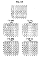
- Figures 34a through 34e illustrate the MAX, PMAX, MIN, and PMIN operations. More specifically, Figure 34a shows a 7 x 7 array of numbers; and each number represents a data value for an associated pixel, with the position of the number in the array corresponding to the address of the associated pixel. Hence, for instance, the data value for the pixel at address (1,1) is 7; the data value for the pixel at address (4,1) is 0; and the data values for the pixels at addresses (4,2), (4,7), and (5,2) are 7, 0, and 0, respectively.
- Figure 34b shows the values produced after a MAX operation has been performed on the whole array of numbers shown in Figure 34a.
- the data value at address (2,6) is 7 because, in Figure 34a, one of the eight pixels adjacent that pixel address has a value of 7.
- the value at address (6,2) in Figure 34b is 7 because, in the data set of Figure 34a, one of the eight pixels adjacent that pixel address has a value of 7.
- Figure 34c shows the values produced as a result of a PMAX operation on the whole data set of Figure 34a; and for instance, the values at addresses (6,3) and (6,4) in Figure 34c are 7 because, in Figure 34a, each of these two pixel addresses is immediately to the right of a pixel having a value of 7.
- Figures 34d and 34e show the values produced after MIN and PMIN operations, respectively, have been performed on the array of values shown in Figure 34a.
- the value at address (4,3) is zero because, in Figure 34a, one of the eight pixels neighboring address (4,3) has a zero value; and in Figure 34e, the value at address (4,2) is zero because, in Figure 34a, the pixel immediately to the right of that pixel address has a value of zero.
- Figure 35 illustrates a preferred fill-in procedure R 8 .
- the procedure involves 14 separate operations performed on data values for the pixel array 46; and each of these operations is performed, one at a time, over the entire pixel array. These operations are, in order: MAX, PMAX, PMAX, MAX, MAX, PMAX, PMAX, MIN, PMIN, PMIN, MIN, MIN, PMIN, and PMIN. These operations start with the I 9 values for the pixels, and the resulting data values, after all 14 operations are completed, are referred to as the I 11 values.
- processor 64 invokes a second masking procedure R 9 to produce a set of pixel illumination values I 12 that is free of the effect of any light incident on pixel array 46 within a given radius of the center point of the circle fitted to the inside edge 150b of annulus 150 during the decentration test.
- this set of pixel illumination values I 12 is subsequently used to help identify defects in the interior of the lens --that is, in the area radially inside the inside edge of annulus 150.
- the masking procedure R 9 employed at this stage of the lens inspection process is very similar to the masking routine R 3 shown in Figures 19a-19c and 20.
- the principle difference between these two masking procedures is that the radius of the mask used in procedure R 9 is slightly smaller than the radius of the circle fitted to the inside edge of annulus 150, while the radius of the mask used in procedure R 3 is slightly larger than the radius of the circle fitted to the outside edge of annulus 150.
- Figure 37 is a flow chart illustrating a preferred masking routine R 9 .
- the first step 446 in this routine is to determine whether at steps 216 or 226 of the decentration test, at least three pixels had been found on the inside edge of annulus 150, or if the ophthalmic lens was found to be badly decentered. If the lens had been found to be badly decentered at either of these two steps of the decentration test, then masking routine R 9 itself terminates at step 450.
- routine R 9 does not terminate at step 450, the routine proceeds to step 452, which is to obtain the coordinate of the center of the circle that had been fitted to the inside edge 150b of annulus 150 during the decentration test. These coordinates had been determined and then stored in processor memory during the decentration test, and these coordinates can be obtained by simply retrieving them from the processor memory. Once these center coordinates are obtained, a mask subroutine is invoked at step 454.
- this subroutine in effect, superimposes over pixel array 46, a circular mask 456 centered on the above-mentioned center coordinates and having a diameter slightly smaller than the diameter of the circle fitted to the inside edge 150b of annulus 150, and then the masking subroutine assigns an I 12 value to each pixel.
- the masking subroutine assigns the pixel an I 12 value equal to the I 8 value for the pixel; and for each pixel inside the mask, the masking subroutine assigns the pixel an I 12 value of zero.
- step 452 the coordinate (x i , y i ) of the above-mentioned center point and a radius value r 2 , which is selected to be slightly smaller than the radius of the circle fitted to the inside edge of annulus 150, are transmitted to the mask subroutine. Then, at step 454, this subroutine forms a file f 5 of the addresses of all of the pixels in array 46 that are within the distance r 2 of that center point (x i ,y i ). Then, at step 460, the address of each pixel in array 46 is checked to determine if it is in that file.
- the I 12 value of the pixel is set to zero; however, if the pixel address is not on the list, then at step 464, the I 12 value of the pixel is set equal to the I 8 value of the pixel.
- Figure 38c shows the pixels of array 46 illuminated at intensities equal to their respective I 12 values.
- a further routine R 10 consisting of a series of operations, is performed to provide a set of pixel illumination values that clearly identify the pixels that are in any irregularity or defect in the lens being inspected. More specifically, the purpose of these further operations is to provide a set of pixel illumination values that is free of any effect produced on array 46 by background noise or light as well as any effect produced on array 46 by the normal or regular edges 150a and 150b of annulus 150. These further operations are shown in the flow chart of Figure 39.
- a further I value, I 13 is obtained for each pixel; and in particular, the I 13 value for each pixel is obtained by subtracting the I 12 value for the pixel from the I 10 value for the pixel.
- Figures 40a, 40b, and 40c show the pixels in a portion of annulus 162 illuminated at intensities equal to their I 10 , I 12 , and I 13 values, respectively; and as can be seen, the practical effect of step 466 is to subtract the image of Figure 40b from the image of Figure 40a to produce the image of Figure 40c.
- an operation referred to as a clean-up operation, is performed to, in effect, help eliminate spurious illuminated pixels. More particularly, starting with the I 13 values for the pixels, MAX, MIN, PMIN, and PMAX operations are performed, in that order, on the entire pixel array 46, producing a further set of pixel values referred to as I 14 values.
- Figure 40d shows the pixels of annulus 46 illuminated at intensities equal to their respective I 14 values; and as can be seen by comparing Figures 40c and 40d, the effect of the clean-up operation is simply to eliminate various isolated pixels that, for one reason or another, are illuminated in Figure 40c.
- Figures 41a and 41 b show a flow chart illustrating a preferred defect detection or analysis routine R 11 .
- This analysis may be best understood with reference to Figure 42, which shows the pixels of a portion of annulus 150 illuminated at intensities equal to their respective I 14 values.
- a list is made of the addresses of the pixels at the start and at the end of each horizontal series of consecutive illuminated pixels, referred to as a run length. More specifically, processor 64, in effect, scans across each horizontal row of pixels in array 46; and during each scan, each time a series of illuminated pixels is encountered, the addresses of the first and last pixels in that series are recorded in file f 6 .
- the processor does not in fact scan across an image of the pixel array, but instead compiles the above-mentioned address list by checking the I 14 values stored in the processor memory for the pixels in array 46.
- routine R 11 invokes a clustering subroutine at step 476 to create a separate file f 6a ...f 6n for each area or group of contiguous illuminated pixels --or, more precisely, for each area or group of contiguous pixels having high I 14 values. Any suitable clustering subroutine may be employed to do this clustering.
- routine R 11 invokes a clustering subroutine at step 476 to create a separate file f 6a ...f 6n for each area or group of contiguous illuminated pixels --or, more precisely, for each area or group of contiguous pixels having high I 14 values. Any suitable clustering subroutine may be employed to do this clustering.
- the files for illuminated areas that are near to each other such as those shown at 482 and 484 of Figure 42, are merged. This may be done, for instance, by checking to determine if any pixel in one illuminated area is within a given number of pixels, such as two or three pixels, of any pixel in another illuminated area. These close illuminated areas are considered as forming
- step 480 subroutines are invoked at step 486 to compute the area and centroid of, and a bounding box for, each area of illuminated pixels.
- Numerous subroutines are well-known in the art for performing these computations. Any such suitable subroutines may be employed in routine R 11 , and it is not necessary to describe these subroutines in detail herein.
- routine R 11 determines the general location of each illuminated area. More specifically, at step 490, the address of the centers and the radii of the two circles fitted to the outer and inner edges 150a and 150b of annulus 150 are obtained. These data were determined or found during the decentration test and were then stored in the processor memory, and these data can be obtained by simply retrieving the data from that processor memory. Then, at step 492, processor 64 determines whether the centroid of each area of illuminated pixels is located (i) inside the central zone of the lens (the area radially inside the circle fitted to the inner edge of the annulus), or (ii) the peripheral zone of the lens (the area of the lens between the two circles fitted to the inner and outer edges of the annulus).
- Steps 490 and 492 are not necessary to the operation of system 10 in its broadest sense. Preferably, though, these steps are done and the associated data are collected for analysis purposes, and in particular, to help identify where possible irregularities or defects are occurring in the lenses. These data may be helpful in adjusting or refining the procedure or materials used to make the lenses.
- the processor determines whether the size of each illuminated area of pixels is sufficiently large to qualify as a flaw or defect for which the lens may be rejected. More specifically, at step 494, the size of each area of illuminated pixels is compared to a preselected size. If that illuminated area is smaller than that preselected size, then the illuminated area is not sufficient to reject the lens. However, if that area of illuminated pixels is larger than the preselected size, then that illuminated area qualifies as a flaw or defect that makes the lens unsuitable for consumer use. This preselected size may be stored, for example, in memory unit 70.
- a count is maintained of the number of defects found in each lens. This count may also be useful for analyzing the process and materials used to make the lenses.
- a display is produced on monitor 72 showing the areas of illuminated pixels, with those areas that are larger than the above-mentioned threshold size being shown within a bounding box.
- processor 64 checks to determine if any defects were in fact found in the lens. If a defect had been found, then at step 504 a reject lens signal is generated and transmitted to monitor 72 and printer 76, and the lens may be removed from system 10. If, however, no defect had been found in the lens, then routine R 11 simply terminates. Subsequently, system 10 operates to move another lens past illuminated subsystem 14 and another pulse of light is transmitted through that other lens. This transmitted light is focused on pixel array 46 and the above-described processing procedure is repeated to determine if this other lens is acceptable for consumer use.
Claims (14)
- Système d'inspection de lentille (10) pour inspecter des lentilles ophtalmiques (114), comprenant :dans lequel le moyen de direction comprend :un sous-système de transport (12), incluant un moyen (110) de maintien d'une lentille ophtalmique (114), afin de déplacer en continu une multitude desdites lentilles ophtalmiques le long d'un chemin prédéterminé pour déplacer chacune de ces lentilles, une par une, dans une position d'inspection de lentille (144) ;un moyen d'illumination (30) pour créer des impulsions de lumière (82) ;un moyen créant un signal (46) pour créer un jeu de signaux représentant l'intensité de lumière incidente dessus ;des moyens (32, 34, 120, 122) pour diriger une impulsion de lumière (82) à travers chaque moyen de maintien de lentille (110) au fur et à mesure qu'il se déplace en continu à travers la position d'inspection de lentille (144), et sur ledit moyen créant un signal (46) pour produire dessus un motif de lumière représentant la lentille ophtalmique (114) maintenue dans le moyen de maintien (110) ; etun moyen de traitement (14) relié au moyen créant un signal (46) pour recevoir ledit jeu de signaux en provenance de celui-ci, et pour traiter lesdits signaux selon un programme prédéterminé pour créer un signal de sortie représentant au moins un état de la lentille (114) ;un arrêt (40) disposé axialement entre le moyen de maintien de lentille (110) et le moyen créant un signal (46) ; etdes moyens (120, 122) pour diriger des portions des impulsions de lumière (82) diffusées par la lentille ophtalmique (114) au-delà de l'arrêt (40), au fur et à mesure que chaque lentille ophtalmique (114) se déplace en continu à travers la position d'inspection (144), et sur le moyen créant un signal (46) de façon à imager dessus des parties choisies de la lentille ophtalmique (114).
- Système d'inspection de lentille (10) selon la revendication 1, dans lequel le moyen pour diriger des portions des impulsions de lumière (82) diffusées par la lentille ophtalmique (114) au-delà de l'arrêt (40) et sur le moyen créant un signal (46) inclut une première lentille (120) disposée entre le moyen de maintien de lentille (110) et l'arrêt (40) pour recevoir la lumière transmise par la lentille ophtalmique (114), pour diriger une portion de ladite lumière transmise sur l'arrêt (40) et pour diriger lesdites portions diffusées de ladite lumière transmise sur le moyen créant un signal (46).
- Système d'inspection de lentille (10) selon la revendication 2, dans lequel le moyen pour diriger les portions des impulsions de lumière (82) diffusées par la lentille ophtalmique (114) au-delà de l'arrêt (40) et sur le moyen créant un signal (46) inclut :une deuxième lentille (122) disposée entre l'arrêt (40) et le moyen créant un signal (46) pour recevoir ladite portion diffusée de ladite lumière transmise provenant de la première lentille (12) et pour diriger ladite portion diffusée de ladite lumière transmise sur le moyen créant un signal (46).
- Système d'inspection de lentille selon la revendication 3, dans lequel la première lentille (120) possède des plans focaux frontal et arrière et une longueur focale, et dans lequel :la lentille ophtalmique (114) est disposée approximativement au plan focal frontal de la première lentille (120) ; etla deuxième lentille (122) est séparée de la première lentille (120) par approximativement la longueur focale de la première lentille (120).
- Système d'inspection de lentille selon la revendication 3, dans lequel la deuxième lentille (122) possède des plans focaux frontal et arrière et une longueur focale, et dans lequel :la matrice de pixels (46) est située approximativement au plan focal arrière de la deuxième lentille (122) ; etla lentille ophtalmique (114) est disposée approximativement au plan focal frontal de la deuxième lentille ; etla première lentille est séparée de la deuxième lentille approximativement par la longueur focale de la deuxième lentille.
- Système d'inspection de lentille (10) selon la revendication 1, dans lequel le moyen pour diriger des portions des impulsions de lumière (82) diffusées par la lentille ophtalmique (114) au-delà de l'arrêt (40) et sur le moyen créant un signal (46) inclut :une première lentille (172) disposée sur un premier côté du moyen de maintien de lentille (110) pour diriger les impulsions de lumière (82) à travers la lentille ophtalmique (114) et pour diriger sur l'arrêt (40) une portion de la lumière dirigée à travers la lentille ophtalmique (114) ; etune deuxième lentille (174) disposée sur un deuxième côté du moyen de maintien de lentille (110) et entre l'arrêt (40) et le moyen créant un signal (46) pour recevoir et pour diriger sur le moyen créant un signal (46) ladite portion diffusée de la lumière dirigée à travers la lentille ophtalmique (114).
- Système d'inspection de lentille (10) selon l'une quelconque des revendications 1 à 6, dans lequel le moyen de direction inclue :un premier miroir (34) pour recevoir les impulsions de lumière (82) provenant du moyen d'illumination (30) et pour diriger les impulsions de lumière (82) sur un chemin donné à travers le moyen de maintien de lentille (110) ; etun moyen (140) supportant de façon mobile le premier miroir (34) pour ajuster la direction dans laquelle les impulsions de lumière (82) sont dirigées à travers le moyen de maintien de lentille (110).
- Système d'inspection de lentille (10) selon la revendication 7, dans lequel le moyen de direction inclut de plus :un deuxième miroir (32) pour recevoir les impulsions de lumière (82) provenant du moyen d'illumination (30) et pour diriger les impulsions de lumière (82) sur le premier miroir (34).
- Système d'inspection de lentille selon la revendication 7 ou 8, dans lequel :le moyen de direction inclut un boítier (26) ;le moyen d'illumination (30) et le premier miroir (34) sont disposés dans le boítier (26) ;le boítier (26) inclut :i) une surface formant une ouverture (26d) située directement au-dessous du moyen de maintien de lentille (110) ; etii) une fenêtre (142) disposée dans ladite ouverture (26d) ;le premier miroir (34) dirige les impulsions de lumière (82) à travers la fenêtre (142) et à travers le moyen de maintien de lentille (110) ; etle boítier (26) inclut de plus un joint d'étanchéité s'étendant autour de la fenêtre (142) et de ladite surface du boítier pour empêcher les fluides provenant du moyen de maintien de lentille (110) d'entrer dans le boítier (26) à travers l'interface entre la fenêtre (142) et ladite surface de boítier.
- Système d'inspection de lentille (10) selon l'une quelconque des revendications 1 à 9, dans lequel le moyen de direction inclue de plus un moyen (136) supportant de façon mobile le moyen d'illumination (30) pour ajuster la direction dans laquelle les impulsions de lumière (82) sont transmises à partir du moyen d'illumination (30).
- Système d'inspection de lentille (10) selon l'une quelconque des revendications précédentes, dans lequel :le moyen créant un signal comprend une matrice (46) de pixels (146a, 146b).
- Système d'inspection de lentille selon l'une quelconque des revendications précédentes, dans lequel au moins un état de la lentille (114) est un état choisi dans le groupe formé par un défaut des bords, un défaut intérieur et un décentrement.
- Système d'inspection de lentille (10) selon l'une quelconque des revendications précédentes, dans lequel le moyen pour diriger les impulsions de lumière (32) à travers le moyen de maintien de lentille (110) dirige les impulsions de lumière (82) à travers le moyen de maintien de lentille (110), dirige les impulsions de lumière (82) le long d'un chemin donné, et inclut de plus un diaphragme ajustable (130) situé sur ledit chemin donné pour ajuster la taille de la surface en coupe transversale des impulsions de lumière (82).
- Système d'inspection de lentille (10) selon la revendication 13 destine à une utilisation avec des lentilles ophtalmiques (114) ayant un diamètre prédéfini, dans lequel le diaphragme (130) limite la surface en coupe transversale des impulsions de lumière (82) de sorte que les impulsions de lumière (82) illuminent une surface circulaire plus grande d'environ 10% à 15% que ledit diamètre prédéfini.
Applications Claiming Priority (2)
| Application Number | Priority Date | Filing Date | Title |
|---|---|---|---|
| US99456592A | 1992-12-21 | 1992-12-21 | |
| US994565 | 1992-12-21 |
Publications (4)
| Publication Number | Publication Date |
|---|---|
| EP0605990A2 EP0605990A2 (fr) | 1994-07-13 |
| EP0605990A3 EP0605990A3 (en) | 1994-09-21 |
| EP0605990B1 EP0605990B1 (fr) | 1998-07-22 |
| EP0605990B2 true EP0605990B2 (fr) | 2003-10-29 |
Family
ID=25540805
Family Applications (1)
| Application Number | Title | Priority Date | Filing Date |
|---|---|---|---|
| EP93310341A Expired - Lifetime EP0605990B2 (fr) | 1992-12-21 | 1993-12-20 | Sous-systèmes d'éclairage et d'imagerie pour un système d'inspection de lentilles |
Country Status (23)
| Country | Link |
|---|---|
| US (1) | US5528357A (fr) |
| EP (1) | EP0605990B2 (fr) |
| JP (1) | JPH06229877A (fr) |
| KR (1) | KR100222772B1 (fr) |
| CN (1) | CN1071895C (fr) |
| AT (1) | ATE168772T1 (fr) |
| AU (1) | AU680444B2 (fr) |
| BR (1) | BR9305157A (fr) |
| CA (1) | CA2111744C (fr) |
| CZ (1) | CZ278093A3 (fr) |
| DE (1) | DE69319875T3 (fr) |
| ES (1) | ES2119870T3 (fr) |
| FI (1) | FI935738A (fr) |
| GR (1) | GR1002219B (fr) |
| GT (1) | GT199300068A (fr) |
| HK (1) | HK1003090A1 (fr) |
| HU (1) | HUT65842A (fr) |
| IL (1) | IL107601A (fr) |
| MX (1) | MX9400084A (fr) |
| NO (1) | NO934713L (fr) |
| NZ (1) | NZ250422A (fr) |
| TW (1) | TW274580B (fr) |
| ZA (1) | ZA939541B (fr) |
Families Citing this family (38)
| Publication number | Priority date | Publication date | Assignee | Title |
|---|---|---|---|---|
| NZ250042A (en) | 1992-12-21 | 1997-01-29 | Johnson & Johnson Vision Prod | Robotic inspection of ophthalmic lenses |
| GR1002574B (el) * | 1992-12-21 | 1997-02-06 | Johnson & Johnson Vision Products Inc. | Παλλετα για την υποδοχη και μεταφορα δοχειων οφθαλμικων φακων. |
| TW325744U (en) * | 1993-07-21 | 1998-01-21 | Ciba Geigy Ag | Two-sided contact lens mold |
| DE69428381T2 (de) | 1993-07-29 | 2002-08-08 | Jessen Wesley Corp | System zur Inspection von optischen Bauelementen |
| AU768049B2 (en) * | 1993-07-29 | 2003-11-27 | Novartis Ag | Inspection system for optical components |
| JP3734512B2 (ja) * | 1993-12-27 | 2006-01-11 | 株式会社メニコン | コンタクトレンズ外観検査方法および外観検査装置 |
| US6226032B1 (en) * | 1996-07-16 | 2001-05-01 | General Signal Corporation | Crystal diameter control system |
| US5801822A (en) * | 1997-02-06 | 1998-09-01 | Pbh, Inc. | Ophthalmic lens inspection system |
| US5818573A (en) * | 1997-02-06 | 1998-10-06 | Pbh, Inc. | Opthalmic lens inspection system |
| DE29901791U1 (de) * | 1999-02-02 | 2000-07-06 | Novartis Ag | Linsenmesseinrichtung |
| US6577387B2 (en) | 2000-12-29 | 2003-06-10 | Johnson & Johnson Vision Care, Inc. | Inspection of ophthalmic lenses using absorption |
| US6765661B2 (en) | 2001-03-09 | 2004-07-20 | Novartis Ag | Lens inspection |
| US7256881B2 (en) * | 2002-02-15 | 2007-08-14 | Coopervision, Inc. | Systems and methods for inspection of ophthalmic lenses |
| US7330579B2 (en) | 2002-11-13 | 2008-02-12 | Johnson & Johnson Vision Care, Inc. | Automated inspection of tinted ophthalmic parts |
| US20060232766A1 (en) * | 2005-03-31 | 2006-10-19 | Watterson Robert J Jr | Methods of inspecting ophthalmic lenses |
| CN101493562A (zh) * | 2008-01-21 | 2009-07-29 | 鸿富锦精密工业(深圳)有限公司 | 镜筒旋入装置及镜筒定位方法 |
| US7990531B2 (en) * | 2008-06-05 | 2011-08-02 | Coopervision International Holding Company, Lp | Multi-imaging automated inspection methods and systems for wet ophthalmic lenses |
| FR2932566B1 (fr) * | 2008-06-12 | 2010-11-19 | Essilor Int | Dispositif de demonstration et de test des qualites cosmetiques d'une lentille ophtalmique |
| RS52882B (en) | 2010-07-30 | 2014-02-28 | Novartis Ag | Silicone Hydrogel Lenses with Rich Water Surfaces |
| JP5960252B2 (ja) | 2011-06-03 | 2016-08-02 | ジョンソン・アンド・ジョンソン・ビジョン・ケア・インコーポレイテッドJohnson & Johnson Vision Care, Inc. | 眼科用レンズの複数放射検査 |
| US8634068B2 (en) | 2011-06-16 | 2014-01-21 | Johnson & Johnson Vision Care, Inc. | Method of determining the optimal wavelength for inspecting ophthalmic lenses |
| US20120320374A1 (en) | 2011-06-17 | 2012-12-20 | Sites Peter W | Method of imaging and inspecting the edge of an ophthalmic lens |
| MY164605A (en) | 2011-10-12 | 2018-01-30 | Novartis Ag | Method for making uv-absorbing ophthalmic lenses |
| TWI458951B (zh) * | 2012-04-19 | 2014-11-01 | Benq Materials Corp | 隱形眼鏡檢測系統 |
| US10338408B2 (en) | 2012-12-17 | 2019-07-02 | Novartis Ag | Method for making improved UV-absorbing ophthalmic lenses |
| TWI451076B (zh) * | 2013-02-08 | 2014-09-01 | Benq Materials Corp | 光學鏡片髒汙檢測方法 |
| US9708087B2 (en) | 2013-12-17 | 2017-07-18 | Novartis Ag | Silicone hydrogel lens with a crosslinked hydrophilic coating |
| CN103837545B (zh) * | 2014-03-14 | 2016-05-25 | 华中科技大学 | 一种镜片成像装置及方法 |
| GB2524585A (en) * | 2014-03-28 | 2015-09-30 | Galaxy Optical Services Ltd | Method and system for inspecting bespoke manufactured products |
| SG10201901379TA (en) | 2014-08-26 | 2019-03-28 | Novartis Ag | Method for applying stable coating on silicone hydrogel contact lenses |
| WO2016055861A1 (fr) * | 2014-10-07 | 2016-04-14 | Shamir Optical Industry Ltd. | Procédés et appareil pour l'inspection et le réusinage éventuel de lentilles ophtalmiques bloquées |
| CN105115989B (zh) * | 2015-10-09 | 2018-02-23 | 爱丁堡(南京)光电设备有限公司 | 一种隐形眼镜缺陷的自动检测设备及检测方法 |
| MY184638A (en) | 2015-12-15 | 2021-04-13 | Alcon Inc | Method for applying stable coating on silicone hydrogel contact lenses |
| GB2560951B (en) * | 2017-03-29 | 2020-06-17 | Redlux Ltd | Inspection of components for imperfections |
| SG11202003456VA (en) | 2017-12-13 | 2020-07-29 | Alcon Inc | Method for producing mps-compatible water gradient contact lenses |
| CN108627321B (zh) * | 2018-06-25 | 2020-01-07 | 新视界视光健康产业(南京)有限公司 | 一种眼镜参数自动检测装置 |
| US20220233071A1 (en) * | 2021-01-26 | 2022-07-28 | Alcon Inc. | Method for the inspection of an ophthalmic lens for semi-opaque defects |
| CN113984790A (zh) * | 2021-09-28 | 2022-01-28 | 歌尔光学科技有限公司 | 镜片质量检测方法及装置 |
Citations (2)
| Publication number | Priority date | Publication date | Assignee | Title |
|---|---|---|---|---|
| US3930713A (en) † | 1973-06-22 | 1976-01-06 | Ernst Leitz G.M.B.H. | Incident light illumination instrument for selective light and dark field illumination |
| US4127318A (en) † | 1975-09-20 | 1978-11-28 | Ernst Leitz Wetzlar Gmbh | Direct illumination apparatus for light and dark field illumination |
Family Cites Families (20)
| Publication number | Priority date | Publication date | Assignee | Title |
|---|---|---|---|---|
| US3770969A (en) * | 1972-03-09 | 1973-11-06 | Owens Illinois Inc | Inspecting the bottom wall of hollow open-ended containers |
| US3904294A (en) * | 1973-12-28 | 1975-09-09 | Polaroid Corp | Automatic lens testing apparatus |
| US3988068A (en) * | 1974-05-09 | 1976-10-26 | Itek Corporation | Method and apparatus for detecting cosmetic defects in opthalmic lenses |
| US4002823A (en) * | 1974-11-01 | 1977-01-11 | Ball Corporation | Method and apparatus for video inspection of articles of manufacture |
| DD119481A1 (fr) * | 1975-02-24 | 1976-04-20 | ||
| US4209252A (en) * | 1978-07-03 | 1980-06-24 | Arditty Herve J | Optical probe assembly for detecting the position of an object surface and method |
| DD138110A1 (de) * | 1978-07-27 | 1979-10-10 | Horst Riesenberg | Auflicht-beleuchtungseinrichtung fuer mikroskope |
| DD145805B1 (de) * | 1979-08-27 | 1982-06-30 | Johannes Grosser | Beleuchtungsanordnung fuer mikroskope |
| DE3115634A1 (de) * | 1981-04-18 | 1982-11-04 | Feldmühle AG, 4000 Düsseldorf | Verfahren und vorrichtung zum pruefen von durch kreislinien begrenzten flaechen |
| US4733360A (en) * | 1984-06-14 | 1988-03-22 | Dai Nippon Insatsu Kabushiki Kaisha | Device and method for inspecting card-like articles |
| DE3432002A1 (de) * | 1984-08-31 | 1986-03-06 | Fa. Carl Zeiss, 7920 Heidenheim | Verfahren und vorrichtung zur optischen untersuchung von kontaktlinsen |
| US5068799A (en) * | 1985-04-24 | 1991-11-26 | Jarrett Jr Harold M | System and method for detecting flaws in continuous web materials |
| US4817166A (en) * | 1986-05-05 | 1989-03-28 | Perceptics Corporation | Apparatus for reading a license plate |
| DE3620129A1 (de) * | 1986-06-14 | 1987-12-17 | Zeiss Carl Fa | Vorrichtung zum pruefen von bauteilen aus transparentem material auf oberflaechenfehler und einschluesse |
| US5081685A (en) * | 1988-11-29 | 1992-01-14 | Westinghouse Electric Corp. | Apparatus and method for reading a license plate |
| JPH02257007A (ja) * | 1989-03-30 | 1990-10-17 | Seiko Epson Corp | コンタクトレンズ外周欠け検査装置 |
| US5249029A (en) * | 1989-09-02 | 1993-09-28 | Bayer Aktiengesellschaft | Apparatus for determining the size distribution of pigment particles in a paint surface |
| US5100232A (en) * | 1990-11-05 | 1992-03-31 | American Optical Corporation | Apparatus and method for detecting hidden marks on progressive aspheric ophthalmic lenses |
| JPH0776757B2 (ja) * | 1990-12-14 | 1995-08-16 | インターナショナル・ビジネス・マシーンズ・コーポレイション | 光学的検査装置 |
| AU649291B2 (en) * | 1990-12-19 | 1994-05-19 | Bodenseewerk Geratetechnik Gmbh | Process and apparatus for examining optical components, especially optical components for the eye and device for illuminating clear-transparent test-objects |
-
1993
- 1993-11-14 IL IL107601A patent/IL107601A/xx not_active IP Right Cessation
- 1993-11-30 HU HU9303399A patent/HUT65842A/hu unknown
- 1993-12-01 GR GR930100476A patent/GR1002219B/el unknown
- 1993-12-10 NZ NZ250422A patent/NZ250422A/en unknown
- 1993-12-15 AU AU52418/93A patent/AU680444B2/en not_active Expired
- 1993-12-15 GT GT199300068A patent/GT199300068A/es unknown
- 1993-12-16 CZ CZ932780A patent/CZ278093A3/cs unknown
- 1993-12-17 CA CA002111744A patent/CA2111744C/fr not_active Expired - Lifetime
- 1993-12-17 TW TW082110690A patent/TW274580B/zh not_active IP Right Cessation
- 1993-12-20 EP EP93310341A patent/EP0605990B2/fr not_active Expired - Lifetime
- 1993-12-20 ZA ZA939541A patent/ZA939541B/xx unknown
- 1993-12-20 FI FI935738A patent/FI935738A/fi not_active Application Discontinuation
- 1993-12-20 ES ES93310341T patent/ES2119870T3/es not_active Expired - Lifetime
- 1993-12-20 NO NO934713A patent/NO934713L/no unknown
- 1993-12-20 BR BR9305157A patent/BR9305157A/pt not_active IP Right Cessation
- 1993-12-20 DE DE69319875T patent/DE69319875T3/de not_active Expired - Lifetime
- 1993-12-20 JP JP5344808A patent/JPH06229877A/ja active Pending
- 1993-12-20 AT AT93310341T patent/ATE168772T1/de active
- 1993-12-21 KR KR1019930028802A patent/KR100222772B1/ko not_active IP Right Cessation
- 1993-12-21 CN CN93119896A patent/CN1071895C/zh not_active Expired - Lifetime
-
1994
- 1994-01-03 MX MX9400084A patent/MX9400084A/es not_active IP Right Cessation
-
1995
- 1995-02-13 US US08/387,978 patent/US5528357A/en not_active Expired - Lifetime
-
1998
- 1998-03-18 HK HK98102280A patent/HK1003090A1/xx not_active IP Right Cessation
Patent Citations (2)
| Publication number | Priority date | Publication date | Assignee | Title |
|---|---|---|---|---|
| US3930713A (en) † | 1973-06-22 | 1976-01-06 | Ernst Leitz G.M.B.H. | Incident light illumination instrument for selective light and dark field illumination |
| US4127318A (en) † | 1975-09-20 | 1978-11-28 | Ernst Leitz Wetzlar Gmbh | Direct illumination apparatus for light and dark field illumination |
Non-Patent Citations (2)
| Title |
|---|
| "Automated Visual Inspection", Batchelor B.G., Hill D.A., Hodgson D.C., IFS (Publications) Ltd, UK, 1985, pages 61-83, 112, 113, 169 † |
| Bergmann, Schäfer: "Optik", Walter de Gruyter Verlag, 8th Edition, 1987, pages 438-452 † |
Also Published As
Similar Documents
| Publication | Publication Date | Title |
|---|---|---|
| EP0605990B2 (fr) | Sous-systèmes d'éclairage et d'imagerie pour un système d'inspection de lentilles | |
| EP0605171B1 (fr) | Système d'inspection de lentilles | |
| EP0607692B1 (fr) | Procédé d'inspection de lentilles ophtalmiques | |
| EP0775901B1 (fr) | Procédé et dispositif d'inspection automatique de lentilles ophtalmiques | |
| US5443152A (en) | Apparatus for carrying ophthalmic lenses | |
| US5995213A (en) | Lens inspection system | |
| CA2111749C (fr) | Appareil pour transporter des lentilles ophthalmiques | |
| KR100249962B1 (ko) | 안과용렌즈검사방법 |
Legal Events
| Date | Code | Title | Description |
|---|---|---|---|
| PUAI | Public reference made under article 153(3) epc to a published international application that has entered the european phase |
Free format text: ORIGINAL CODE: 0009012 |
|
| AK | Designated contracting states |
Kind code of ref document: A2 Designated state(s): AT BE CH DE DK ES FR GB IE IT LI LU NL PT SE |
|
| PUAL | Search report despatched |
Free format text: ORIGINAL CODE: 0009013 |
|
| AK | Designated contracting states |
Kind code of ref document: A3 Designated state(s): AT BE CH DE DK ES FR GB IE IT LI LU NL PT SE |
|
| 17P | Request for examination filed |
Effective date: 19950223 |
|
| 17Q | First examination report despatched |
Effective date: 19960503 |
|
| GRAG | Despatch of communication of intention to grant |
Free format text: ORIGINAL CODE: EPIDOS AGRA |
|
| GRAG | Despatch of communication of intention to grant |
Free format text: ORIGINAL CODE: EPIDOS AGRA |
|
| GRAH | Despatch of communication of intention to grant a patent |
Free format text: ORIGINAL CODE: EPIDOS IGRA |
|
| GRAH | Despatch of communication of intention to grant a patent |
Free format text: ORIGINAL CODE: EPIDOS IGRA |
|
| GRAA | (expected) grant |
Free format text: ORIGINAL CODE: 0009210 |
|
| AK | Designated contracting states |
Kind code of ref document: B1 Designated state(s): AT BE CH DE DK ES FR GB IE IT LI LU NL PT SE |
|
| REF | Corresponds to: |
Ref document number: 168772 Country of ref document: AT Date of ref document: 19980815 Kind code of ref document: T |
|
| REG | Reference to a national code |
Ref country code: CH Ref legal event code: NV Representative=s name: E. BLUM & CO. PATENTANWAELTE Ref country code: CH Ref legal event code: EP |
|
| REF | Corresponds to: |
Ref document number: 69319875 Country of ref document: DE Date of ref document: 19980827 |
|
| ITF | It: translation for a ep patent filed |
Owner name: SOCIETA' ITALIANA BREVETTI S.P.A. |
|
| ET | Fr: translation filed | ||
| REG | Reference to a national code |
Ref country code: ES Ref legal event code: FG2A Ref document number: 2119870 Country of ref document: ES Kind code of ref document: T3 |
|
| PG25 | Lapsed in a contracting state [announced via postgrant information from national office to epo] |
Ref country code: PT Free format text: LAPSE BECAUSE OF FAILURE TO SUBMIT A TRANSLATION OF THE DESCRIPTION OR TO PAY THE FEE WITHIN THE PRESCRIBED TIME-LIMIT Effective date: 19981022 Ref country code: DK Free format text: LAPSE BECAUSE OF FAILURE TO SUBMIT A TRANSLATION OF THE DESCRIPTION OR TO PAY THE FEE WITHIN THE PRESCRIBED TIME-LIMIT Effective date: 19981022 |
|
| REG | Reference to a national code |
Ref country code: IE Ref legal event code: FG4D |
|
| PG25 | Lapsed in a contracting state [announced via postgrant information from national office to epo] |
Ref country code: LU Free format text: LAPSE BECAUSE OF NON-PAYMENT OF DUE FEES Effective date: 19981220 Ref country code: AT Free format text: LAPSE BECAUSE OF NON-PAYMENT OF DUE FEES Effective date: 19981220 |
|
| PG25 | Lapsed in a contracting state [announced via postgrant information from national office to epo] |
Ref country code: SE Free format text: LAPSE BECAUSE OF NON-PAYMENT OF DUE FEES Effective date: 19981221 |
|
| PG25 | Lapsed in a contracting state [announced via postgrant information from national office to epo] |
Ref country code: LI Free format text: LAPSE BECAUSE OF NON-PAYMENT OF DUE FEES Effective date: 19981231 Ref country code: CH Free format text: LAPSE BECAUSE OF NON-PAYMENT OF DUE FEES Effective date: 19981231 Ref country code: BE Free format text: LAPSE BECAUSE OF NON-PAYMENT OF DUE FEES Effective date: 19981231 |
|
| PLBI | Opposition filed |
Free format text: ORIGINAL CODE: 0009260 |
|
| PLBF | Reply of patent proprietor to notice(s) of opposition |
Free format text: ORIGINAL CODE: EPIDOS OBSO |
|
| 26 | Opposition filed |
Opponent name: NOVARTIS AG Effective date: 19990421 |
|
| BERE | Be: lapsed |
Owner name: JOHNSON & JOHNSON VISION PRODUCTS INC. Effective date: 19981231 |
|
| PG25 | Lapsed in a contracting state [announced via postgrant information from national office to epo] |
Ref country code: NL Free format text: LAPSE BECAUSE OF NON-PAYMENT OF DUE FEES Effective date: 19990701 |
|
| REG | Reference to a national code |
Ref country code: CH Ref legal event code: PL |
|
| NLV4 | Nl: lapsed or anulled due to non-payment of the annual fee |
Effective date: 19990701 |
|
| PLBF | Reply of patent proprietor to notice(s) of opposition |
Free format text: ORIGINAL CODE: EPIDOS OBSO |
|
| PLBF | Reply of patent proprietor to notice(s) of opposition |
Free format text: ORIGINAL CODE: EPIDOS OBSO |
|
| PG25 | Lapsed in a contracting state [announced via postgrant information from national office to epo] |
Ref country code: ES Free format text: LAPSE BECAUSE OF NON-PAYMENT OF DUE FEES Effective date: 19991221 |
|
| PLBF | Reply of patent proprietor to notice(s) of opposition |
Free format text: ORIGINAL CODE: EPIDOS OBSO |
|
| RDAH | Patent revoked |
Free format text: ORIGINAL CODE: EPIDOS REVO |
|
| APAC | Appeal dossier modified |
Free format text: ORIGINAL CODE: EPIDOS NOAPO |
|
| APAE | Appeal reference modified |
Free format text: ORIGINAL CODE: EPIDOS REFNO |
|
| APAC | Appeal dossier modified |
Free format text: ORIGINAL CODE: EPIDOS NOAPO |
|
| REG | Reference to a national code |
Ref country code: GB Ref legal event code: IF02 |
|
| PLBQ | Unpublished change to opponent data |
Free format text: ORIGINAL CODE: EPIDOS OPPO |
|
| PLAB | Opposition data, opponent's data or that of the opponent's representative modified |
Free format text: ORIGINAL CODE: 0009299OPPO |
|
| R26 | Opposition filed (corrected) |
Opponent name: NOVARTIS AG Effective date: 19990421 |
|
| APAC | Appeal dossier modified |
Free format text: ORIGINAL CODE: EPIDOS NOAPO |
|
| PLAW | Interlocutory decision in opposition |
Free format text: ORIGINAL CODE: EPIDOS IDOP |
|
| PUAH | Patent maintained in amended form |
Free format text: ORIGINAL CODE: 0009272 |
|
| STAA | Information on the status of an ep patent application or granted ep patent |
Free format text: STATUS: PATENT MAINTAINED AS AMENDED |
|
| 27A | Patent maintained in amended form |
Effective date: 20031029 |
|
| AK | Designated contracting states |
Kind code of ref document: B2 Designated state(s): AT BE CH DE DK ES FR GB IE IT LI LU NL PT SE |
|
| REG | Reference to a national code |
Ref country code: ES Ref legal event code: FD2A Effective date: 20000114 |
|
| ET3 | Fr: translation filed ** decision concerning opposition | ||
| APAH | Appeal reference modified |
Free format text: ORIGINAL CODE: EPIDOSCREFNO |
|
| PGFP | Annual fee paid to national office [announced via postgrant information from national office to epo] |
Ref country code: DE Payment date: 20121213 Year of fee payment: 20 Ref country code: IE Payment date: 20121211 Year of fee payment: 20 |
|
| PGFP | Annual fee paid to national office [announced via postgrant information from national office to epo] |
Ref country code: GB Payment date: 20121219 Year of fee payment: 20 Ref country code: IT Payment date: 20121218 Year of fee payment: 20 |
|
| PGFP | Annual fee paid to national office [announced via postgrant information from national office to epo] |
Ref country code: FR Payment date: 20130107 Year of fee payment: 20 |
|
| REG | Reference to a national code |
Ref country code: DE Ref legal event code: R071 Ref document number: 69319875 Country of ref document: DE |
|
| REG | Reference to a national code |
Ref country code: GB Ref legal event code: PE20 Expiry date: 20131219 |
|
| REG | Reference to a national code |
Ref country code: IE Ref legal event code: MK9A |
|
| PG25 | Lapsed in a contracting state [announced via postgrant information from national office to epo] |
Ref country code: DE Free format text: LAPSE BECAUSE OF EXPIRATION OF PROTECTION Effective date: 20131221 Ref country code: GB Free format text: LAPSE BECAUSE OF EXPIRATION OF PROTECTION Effective date: 20131219 |
|
| PG25 | Lapsed in a contracting state [announced via postgrant information from national office to epo] |
Ref country code: IE Free format text: LAPSE BECAUSE OF EXPIRATION OF PROTECTION Effective date: 20131220 |