EP0605301B1 - Réflectomètre optique à domaine de temps - Google Patents
Réflectomètre optique à domaine de temps Download PDFInfo
- Publication number
- EP0605301B1 EP0605301B1 EP93403155A EP93403155A EP0605301B1 EP 0605301 B1 EP0605301 B1 EP 0605301B1 EP 93403155 A EP93403155 A EP 93403155A EP 93403155 A EP93403155 A EP 93403155A EP 0605301 B1 EP0605301 B1 EP 0605301B1
- Authority
- EP
- European Patent Office
- Prior art keywords
- light
- optical fiber
- optical
- directional coupler
- delay
- Prior art date
- Legal status (The legal status is an assumption and is not a legal conclusion. Google has not performed a legal analysis and makes no representation as to the accuracy of the status listed.)
- Expired - Lifetime
Links
Images


Classifications
-
- G—PHYSICS
- G01—MEASURING; TESTING
- G01M—TESTING STATIC OR DYNAMIC BALANCE OF MACHINES OR STRUCTURES; TESTING OF STRUCTURES OR APPARATUS, NOT OTHERWISE PROVIDED FOR
- G01M11/00—Testing of optical apparatus; Testing structures by optical methods not otherwise provided for
- G01M11/30—Testing of optical devices, constituted by fibre optics or optical waveguides
- G01M11/31—Testing of optical devices, constituted by fibre optics or optical waveguides with a light emitter and a light receiver being disposed at the same side of a fibre or waveguide end-face, e.g. reflectometers
- G01M11/3109—Reflectometers detecting the back-scattered light in the time-domain, e.g. OTDR
- G01M11/3145—Details of the optoelectronics or data analysis
Definitions
- the present invention relates to an optical time domain reflectometer which is used in an optical fiber network to inspect damages of the optical fibers.
- the optical time domain reflectometer is an apparatus which measures a damaged point, a transmission loss or a connecting loss of an optical fiber by outputting a light pulse from the OTDR to a measuring optical fiber through an optical waveguide directional coupler, and by detecting a returned light pulse from the measuring optical fiber.
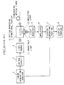
- Fig. 4 is a block diagram showing a conventional OTDR.
- a timing pulse generating portion 1 generates an electrical pulse.
- a driver circuit 2 generates a pulse current according to the electrical pulse, and outputs the pulse current to a light source 3.
- the light source 3 generates a light pulse (laser) according to the pulse current.
- the light pulse is inputted to a measuring optical fiber 10 through an optical waveguide directional coupler 4.
- light such as a back scattering light and a reflected light
- the returned light is transmitted from an optical waveguide directional coupler 4 to a light receiver 5.
- the returned light is then transformed to an electrical signal in a light receiver 5, and the electrical signal is amplified in an amplifier 6.
- the electrical signal from the amplifier 6 is transformed into a digital signal, and an operation, such as an averaging operation, is applied to decrease a noise in the signal in the digital operating portion 7. Furthermore, the digital signal is transformed on the basis of a logarithm, and is then displayed in the display portion 8.
- the back scattering light from the measuring optical fiber 10 is caused by a raleigh scattering light which accrues in the measuring optical fiber 10.
- the level of the back scattering light becomes approximately 50 dB lower value than the level of the inputted light pulse, in the case wherein the measuring optical fiber 10 is a single mode fiber, and the inputted light pulse has a width of 1 x 10 -6 second.
- the velocity of the light pulse when it is transmitted in the optical fiber, is the value which is used to divide an evacuated light velocity with a refractive index of a material of the optical fiber, and thereby the extent of the light pulse in a length direction (along the long axis) of the optical fiber is obtained by producing the velocity and the pulse width of the light pulse.
- the extent of the light pulse becomes approximately one hundred meters in the case of the single mode fiber.
- the extent of the light pulse in the length direction must be a small value in order to improve the resolving power for measurement of the distance to a damaged point. For example, if the inputted light pulse has a width of 1 x 10 -8 second, the extent thereof will be approximately one meter. However, the level of the back scattering light becomes a low value in proportion to the pulse width, that is, the level of the back scattering light becomes approximately 70 dB lower in value than that of the inputted light pulse.
- a cross talk light (L1) which occurs in the optical waveguide directional coupler 4, is directly transmitted to the light receiver 5.
- a reflected light (L2), which occurs at an input connector of the measuring optical fiber 10 via an outputted light from the optical waveguide directional coupler 4 is refracted, and is transmitted to the light receiver.
- This cross talk light (L1) and reflected light (L2) is supplied to the light receiver 6 with the back scattering light.
- the level of the cross talk light (L1) is determined by the efficiency of the optical waveguide directional coupler 4, and, in this case, is approximately 40 dB lower value than that of the inputted light pulse.
- the level of the reflected light (L2) is determined by the efficiency of the connector, and becomes approximately 40 dB lower in value than that of the inputted light pulse.
- the cross talk light (L1) and the reflected light (L2) are supplied to the light receiver 5 at approximately the same time, so that both are added, and thus the level of light inputted to the light receiver 5 is two times the value thereof.
- the light receiver 5 must receive only the back scattering light which is approximately 70 dB lower than the inputted light pulse.
- the light receiver 5 receives the sum of the cross talk light (L1) and the reflected light (L2), which is approximately 40 dB lower than the inputted light pulse (i.e. one thousand times the intensity of the back scattering light), with the back scattering light.
- L1 cross talk light
- L2 reflected light
- the light receiver 5 and the amplifier 6 are saturated.
- An interval whereat the light receiver 5 can normally receive the back scattering light after the above mentioned effect decreases, is called a dead zone.
- the level of the back scattering light, the level of the cross talk light(L1), the level of the reflected light (L2) and the level of the sum of the cross talk light (L1) and the reflected light (L2), in the case wherein the width of the light pulse is 1 x 10 -8 second, and the dead zone NT are shown as a display example of the display of the OTDR in Fig. 5.
- the conventional OTDR has a relatively long dead zone NT, and as a result, it is not possible to detect damages to the optical fiber quickly.
- EP-A-453816 discloses the provision of a reference fiber between the front panel of the OTDR and the optical coupler in order to detect the loss or reflection caused by a front panel connector for connecting a test fiber, so as to accurately detect backscattered light. In this case, a time delay necessary for switching the optical coupler from the transmission mode to the detector mode is provided.
- an object of the present invention to provide an OTDR which is used in an optical fiber network to check damages of the optical fibers, having, in particular, a short dead zone.
- an optical time domain reflectometer for detecting the damaged point of an optical fiber, wherein said optical time domain reflectometer supplies a light pulse, which is outputted from a light source to said optical fiber through an optical waveguide directional coupler, and transmits a reflected light outputted from said optical fiber to a light receiver through said optical waveguide directional coupler, then operates a signal outputted from said light receiver with digital treatments in a digital operating portion, furthermore displays a result of said digital operating portion, and said optical time domain reflectometer is comprising:
- Fig. 1 is a block diagram showing the OTDR according to an embodiment of the present invention.
- Fig. 2 is a pictorial view showing a display example of the OTDR when a delay optical fiber is inserted therein, in this embodiment.
- Fig. 3 is a pictorial view showing a display example of the OTDR, wherein the OTDR compensates the origin of the distance via the delay circuit 1.
- Fig. 4 is a block diagram showing a conventional OTDR.
- Fig. 5 is a pictorial view showing a display example of the conventional OTDR.
- Fig. 1 is a block diagram showing the OTDR according to an embodiment of the present invention.
- a delay optical fiber 9 is inserted between the optical waveguide directional coupler 4 and the measuring optical fiber 10.
- the OTDR consists of a delay circuit 11 to delay a timing signal, which is transmitted from the timing generated portion 1 to the digital operating portion 7, by a predetermined time. Accordingly, the digital operating portion 7 is driven by the delayed timing signal.
- the optical waveguide directional coupler 4 and the delay optical fiber 9 are connected by using a melting connecting method, such that no refraction occurs at the connected portion.
- the length of the delay optical fiber 9 is the same as, or longer than, the extent of the light pulse, which is outputted to the measuring optical fiber 10, in the direction of the long axis.
- the distance between the light source 3 and the optical waveguide directional coupler 4, and the distance between the optical waveguide directional coupler 4 and the light receiver 5 is shorter than the above extent.
- the length of the delay optical fiber 9 is approximately one hundred meters longer than the distance between the light source 3 and the optical waveguide directional coupler 4.
- the delay time of the delay circuit 11 is same as the required time that the light pulse goes back and forth in the delay optical fiber 9. That is, the delay time of the delay circuit is 2 x 10 -6 seconds in this embodiment.
- the driver circuit 2 generates a pulse current according to the electrical pulse supplied from the timing generating portion 1, and thus, the light source 3 emits a light pulse.
- the light pulse outputted from the light source 3 goes to the delay optical fiber 9 through the optical waveguide directional coupler 4, and then goes to the measuring optical fiber 10.
- the cross talk light (L1) occurs and is directly transmitted to the light receiver 5.
- the cross talk light (L1) is not transmitted with the reflected light (L2) which occurs at the same time, at the connector of the measuring optical fiber 10.
- Fig. 2 shows a display example of the OTDR in this embodiment.
- the saturation phenomenon of the light receiver 5 and the amplifier 6, by the reflected light (L2) is restricted, so that the release time is shortened.
- the light receiver 5 can receive the back scattering light quickly. That is, it is possible to decrease the dead zone NT.
- the delay circuit 11 delays an operating timing of the digital operating portion 7 by the time required for the light to go back and forth in the delay optical fiber 9.
- the origin of the distance accords with a place on the connector between the delay optical fiber 9 and the measuring optical fiber 10.
- Fig. 3 shows a display example of the OTDR in Fig. 2, in the same scale as that used in Fig. 5, in the case wherein the origin of the distance is compensated by the delay circuit 11.
Landscapes
- Physics & Mathematics (AREA)
- Engineering & Computer Science (AREA)
- Microelectronics & Electronic Packaging (AREA)
- Optics & Photonics (AREA)
- Chemical & Material Sciences (AREA)
- Analytical Chemistry (AREA)
- General Physics & Mathematics (AREA)
- Testing Of Optical Devices Or Fibers (AREA)
- Photometry And Measurement Of Optical Pulse Characteristics (AREA)
- Optical Communication System (AREA)
Claims (3)
- Réflectomètre optique dans le domaine du temps pour détecter le point détérioré d'une fibre optique (10), dans lequel ledit réflectomètre optique dans le domaine du temps applique une impulsion lumineuse qui est délivrée par une source lumineuse (3) à ladite fibre optique (10) à travers un coupleur directionnel à guide d'ondes optiques (4) et transmet la lumière réfléchie délivrée par ladite fibre optique (10) à un récepteur de lumière (5) à travers ledit coupleur directionnel à guide d'ondes optiques (4), puis fait subir à un signal délivré par ledit récepteur de lumière (5) des traitements numériques dans une partie à fonctionnement numérique (7), affiche un résultat de ladite partie à fonctionnement numérique (7) et ledit réflectomètre optique dans le domaine du temps est caractérisé en ce qu'il comprend :une fibre optique à retard (9) pour retarder ladite impulsion lumineuse, ladite fibre optique à retard étant introduite entre ledit coupleur directionnel à guide d'ondes optiques (4) et ladite fibre optique (10) de manière à ne pas appliquer ladite lumière réfléchie et ladite lumière de diaphotie venant du coupleur directionnel à guide d'ondes optiques au récepteur de lumière en même temps, etdes moyens à retard (11) pour retarder une synchronisation du fonctionnement de ladite partie à fonctionnement numérique (7) d'un temps nécessaire pour que ladite impulsion lumineuse effectue un déplacement aller et retour dans la fibre optique à retard (9).
- Réflectomètre optique dans le domaine du temps selon la revendication 1, dans lequel ledit coupleur directionnel à guide d'ondes optiques et ladite fibre optique à retard sont connectés au moyen d'un procédé de connexion par fusion de manière à ce qu'aucune réflexion ne se produise au niveau de la partie connectée.
- Réflectomètre optique dans le domaine du temps selon la revendication 1, dans lequel une longueur de ladite fibre optique à retard est égale ou supérieure à la portée de ladite impulsion lumineuse dans la direction longitudinale de l'axe longitudinal d'une fibre optique ; et
une distance entre ladite source lumineuse et ledit coupleur directionnel à guide d'ondes optiques, et une distance entre ledit coupleur directionnel à guide d'ondes optiques et ledit récepteur de lumière sont plus courtes que ladite portée de ladite impulsion lumineuse dans la direction de l'axe longitudinal d'une fibre optique.
Applications Claiming Priority (2)
| Application Number | Priority Date | Filing Date | Title |
|---|---|---|---|
| JP36024492A JP3206168B2 (ja) | 1992-12-29 | 1992-12-29 | 光パルス試験器 |
| JP360244/92 | 1992-12-29 |
Publications (2)
| Publication Number | Publication Date |
|---|---|
| EP0605301A1 EP0605301A1 (fr) | 1994-07-06 |
| EP0605301B1 true EP0605301B1 (fr) | 1997-03-19 |
Family
ID=18468544
Family Applications (1)
| Application Number | Title | Priority Date | Filing Date |
|---|---|---|---|
| EP93403155A Expired - Lifetime EP0605301B1 (fr) | 1992-12-29 | 1993-12-23 | Réflectomètre optique à domaine de temps |
Country Status (4)
| Country | Link |
|---|---|
| US (1) | US5408310A (fr) |
| EP (1) | EP0605301B1 (fr) |
| JP (1) | JP3206168B2 (fr) |
| DE (1) | DE69309025T2 (fr) |
Families Citing this family (16)
| Publication number | Priority date | Publication date | Assignee | Title |
|---|---|---|---|---|
| US5754284A (en) * | 1996-10-09 | 1998-05-19 | Exfo Electro-Optical Engineering Inc. | Optical time domain reflectometer with internal reference reflector |
| FR2782799B1 (fr) * | 1998-08-27 | 2000-11-17 | France Telecom | Appareil de mesure de paradiaphotie lineique des fibres multicoeurs |
| GB2408571B (en) * | 2003-11-26 | 2006-07-19 | Sensor Highway Ltd | Apparatus and methods for distributed temperature sensing |
| CN101351689B (zh) * | 2006-07-03 | 2011-12-07 | 安立股份有限公司 | 光时域反射仪和用于使用光脉冲来测试光纤的方法 |
| US8059967B2 (en) | 2006-09-29 | 2011-11-15 | Yokogawa Electric Corporation | Optical pulse generator and optical pulse tester |
| KR101051981B1 (ko) * | 2009-04-22 | 2011-07-26 | 대한측량협회 | 거리 측정 장치 및 방법 |
| JP5392914B2 (ja) * | 2010-02-19 | 2014-01-22 | 日本電信電話株式会社 | 光ファイバ測定装置 |
| US20120237205A1 (en) * | 2011-03-16 | 2012-09-20 | Baker Hughes Incorporated | System and method to compensate for arbitrary optical fiber lead-ins in an optical frequency domain reflectometry system |
| US9546915B2 (en) | 2011-10-12 | 2017-01-17 | Baker Hughes Incorporated | Enhancing functionality of reflectometry based systems using parallel mixing operations |
| EP2690420B1 (fr) * | 2012-06-14 | 2014-08-13 | Alcatel Lucent | Procédé pour estimer un profil de réflexion d'un canal optique |
| CZ2014601A3 (cs) * | 2014-09-03 | 2015-12-16 | Vysoké Učení Technické V Brně | Zařízení pro generování periodicky se opakujících sledů optických pulzů a metoda detekce nehomogenit či časově proměnných dějů v optických trasách a jejich okolí využívající uvedeného zařízení |
| CN104269006B (zh) * | 2014-09-24 | 2016-08-03 | 天津大学 | 一种用于光纤预警系统的模式识别方法 |
| JP6571452B2 (ja) * | 2015-08-28 | 2019-09-04 | シャープ株式会社 | 検査装置 |
| CZ2017161A3 (cs) * | 2017-03-21 | 2018-05-09 | Vysoká Škola Báňská - Technická Univerzita Ostrava | Zapojení generátoru časové prodlevy |
| US11624681B2 (en) | 2020-01-16 | 2023-04-11 | Saudi Arabian Oil Company | Overcoming OTDR dead zones using a few-mode fiber |
| CN113328793A (zh) * | 2021-06-17 | 2021-08-31 | 西北核技术研究所 | 基于时域反射差值的远程光纤传输延时测试方法及系统 |
Family Cites Families (5)
| Publication number | Priority date | Publication date | Assignee | Title |
|---|---|---|---|---|
| US4914394A (en) * | 1986-07-31 | 1990-04-03 | Electromagnetic Techology, Inc. | Pocket-size time domain reflectometer |
| DE3721823A1 (de) * | 1987-07-02 | 1989-01-12 | Philips Patentverwaltung | Verfahren zur messung der von einer reflexionsstelle reflektierten optischen strahlungsleistung |
| US5008545A (en) * | 1989-10-23 | 1991-04-16 | Tektronix, Inc. | High resolution optical fault locator |
| US5148230A (en) * | 1990-04-25 | 1992-09-15 | Tektronix, Inc. | Measurement apparatus having improved sample density using nested data acquisitions |
| US5062704A (en) * | 1990-04-25 | 1991-11-05 | Tektronix, Inc. | Optical time domain reflectometer having pre and post front panel connector testing capabilities |
-
1992
- 1992-12-29 JP JP36024492A patent/JP3206168B2/ja not_active Expired - Fee Related
-
1993
- 1993-12-23 DE DE69309025T patent/DE69309025T2/de not_active Expired - Fee Related
- 1993-12-23 EP EP93403155A patent/EP0605301B1/fr not_active Expired - Lifetime
- 1993-12-28 US US08/174,050 patent/US5408310A/en not_active Expired - Fee Related
Also Published As
| Publication number | Publication date |
|---|---|
| JPH06201482A (ja) | 1994-07-19 |
| EP0605301A1 (fr) | 1994-07-06 |
| US5408310A (en) | 1995-04-18 |
| DE69309025T2 (de) | 1997-10-09 |
| DE69309025D1 (de) | 1997-04-24 |
| JP3206168B2 (ja) | 2001-09-04 |
Similar Documents
| Publication | Publication Date | Title |
|---|---|---|
| EP0605301B1 (fr) | Réflectomètre optique à domaine de temps | |
| US5062704A (en) | Optical time domain reflectometer having pre and post front panel connector testing capabilities | |
| US5767956A (en) | Backward brillouin scattering optical time domain reflectometry | |
| EP0153924B1 (fr) | Dispositif et procede de mesure | |
| US6700655B2 (en) | Optical fiber characteristic measuring device | |
| US6459478B1 (en) | Optical loss measurements | |
| US4763009A (en) | Method and apparatus for remotely measuring the distribution of a physico-chemical parameter in a medium | |
| JPH09200132A (ja) | 光通信線路の監視方法 | |
| JP2666827B2 (ja) | 光測定方法 | |
| US5295015A (en) | Optical amplifying apparatus | |
| JP2769185B2 (ja) | 後方散乱光測定装置 | |
| EP0824677B1 (fr) | Methode permettant d'effectuer des mesures sur une fibre optique | |
| EP0138623B1 (fr) | Méthode d'essai pour des fibres optiques et appareil pour sa mise en oeuvre | |
| US6211950B1 (en) | Optical pulse reflectometer | |
| CN110518967B (zh) | 一种单轴光纤干涉仪及消除光纤振动盲区的定位装置 | |
| US7027217B2 (en) | Optical pulse generator and optical pulse testing instrument and method | |
| JP2972973B2 (ja) | 光パルス試験器 | |
| JP3222046B2 (ja) | 光ファイバ歪測定装置 | |
| US6912046B2 (en) | Instrument measuring chromatic dispersion in optical fibers | |
| US5226102A (en) | Light-reflection method for transmission-loss measurements in optical fiber lightguides | |
| JPH11142293A (ja) | Otdr装置 | |
| JP2747565B2 (ja) | 光ファイバの曲率分布測定方法および装置 | |
| US5500731A (en) | Optical time domain reflectometer using ring laser light source | |
| JPS58113832A (ja) | 光フアイバ破断点検出装置 | |
| JPH05102583A (ja) | 光フアイバ増幅器 |
Legal Events
| Date | Code | Title | Description |
|---|---|---|---|
| PUAI | Public reference made under article 153(3) epc to a published international application that has entered the european phase |
Free format text: ORIGINAL CODE: 0009012 |
|
| AK | Designated contracting states |
Kind code of ref document: A1 Designated state(s): DE FR GB |
|
| 17P | Request for examination filed |
Effective date: 19941214 |
|
| 17Q | First examination report despatched |
Effective date: 19950828 |
|
| GRAG | Despatch of communication of intention to grant |
Free format text: ORIGINAL CODE: EPIDOS AGRA |
|
| GRAH | Despatch of communication of intention to grant a patent |
Free format text: ORIGINAL CODE: EPIDOS IGRA |
|
| GRAH | Despatch of communication of intention to grant a patent |
Free format text: ORIGINAL CODE: EPIDOS IGRA |
|
| GRAA | (expected) grant |
Free format text: ORIGINAL CODE: 0009210 |
|
| AK | Designated contracting states |
Kind code of ref document: B1 Designated state(s): DE FR GB |
|
| REF | Corresponds to: |
Ref document number: 69309025 Country of ref document: DE Date of ref document: 19970424 |
|
| ET | Fr: translation filed | ||
| PLBE | No opposition filed within time limit |
Free format text: ORIGINAL CODE: 0009261 |
|
| STAA | Information on the status of an ep patent application or granted ep patent |
Free format text: STATUS: NO OPPOSITION FILED WITHIN TIME LIMIT |
|
| 26N | No opposition filed | ||
| REG | Reference to a national code |
Ref country code: GB Ref legal event code: IF02 |
|
| PGFP | Annual fee paid to national office [announced via postgrant information from national office to epo] |
Ref country code: FR Payment date: 20021210 Year of fee payment: 10 |
|
| PGFP | Annual fee paid to national office [announced via postgrant information from national office to epo] |
Ref country code: GB Payment date: 20021218 Year of fee payment: 10 |
|
| PGFP | Annual fee paid to national office [announced via postgrant information from national office to epo] |
Ref country code: DE Payment date: 20021231 Year of fee payment: 10 |
|
| PG25 | Lapsed in a contracting state [announced via postgrant information from national office to epo] |
Ref country code: GB Free format text: LAPSE BECAUSE OF NON-PAYMENT OF DUE FEES Effective date: 20031223 |
|
| PG25 | Lapsed in a contracting state [announced via postgrant information from national office to epo] |
Ref country code: DE Free format text: LAPSE BECAUSE OF NON-PAYMENT OF DUE FEES Effective date: 20040701 |
|
| GBPC | Gb: european patent ceased through non-payment of renewal fee |
Effective date: 20031223 |
|
| PG25 | Lapsed in a contracting state [announced via postgrant information from national office to epo] |
Ref country code: FR Free format text: LAPSE BECAUSE OF NON-PAYMENT OF DUE FEES Effective date: 20040831 |
|
| REG | Reference to a national code |
Ref country code: FR Ref legal event code: ST |