EP0605183A2 - Dispositif pour tenir des cartouches et les maintenir en état d'alimentation d'encre dans une imprimante à jet d'encre - Google Patents
Dispositif pour tenir des cartouches et les maintenir en état d'alimentation d'encre dans une imprimante à jet d'encre Download PDFInfo
- Publication number
- EP0605183A2 EP0605183A2 EP93310396A EP93310396A EP0605183A2 EP 0605183 A2 EP0605183 A2 EP 0605183A2 EP 93310396 A EP93310396 A EP 93310396A EP 93310396 A EP93310396 A EP 93310396A EP 0605183 A2 EP0605183 A2 EP 0605183A2
- Authority
- EP
- European Patent Office
- Prior art keywords
- ink
- chamber
- cartridge
- cartridges
- container
- Prior art date
- Legal status (The legal status is an assumption and is not a legal conclusion. Google has not performed a legal analysis and makes no representation as to the accuracy of the status listed.)
- Granted
Links
- 239000000976 ink Substances 0.000 claims description 58
- 238000007639 printing Methods 0.000 claims description 15
- 239000003086 colorant Substances 0.000 claims description 4
- 239000000463 material Substances 0.000 description 7
- 238000005192 partition Methods 0.000 description 3
- 230000002745 absorbent Effects 0.000 description 2
- 239000002250 absorbent Substances 0.000 description 2
- 238000007641 inkjet printing Methods 0.000 description 2
- 238000000034 method Methods 0.000 description 2
- 239000002699 waste material Substances 0.000 description 2
- 238000007792 addition Methods 0.000 description 1
- 230000015271 coagulation Effects 0.000 description 1
- 238000005345 coagulation Methods 0.000 description 1
- 230000008878 coupling Effects 0.000 description 1
- 238000010168 coupling process Methods 0.000 description 1
- 238000005859 coupling reaction Methods 0.000 description 1
- 230000001419 dependent effect Effects 0.000 description 1
- 238000001035 drying Methods 0.000 description 1
- 238000010438 heat treatment Methods 0.000 description 1
- 238000004519 manufacturing process Methods 0.000 description 1
- 239000011148 porous material Substances 0.000 description 1
- 229920005989 resin Polymers 0.000 description 1
- 239000011347 resin Substances 0.000 description 1
Images


Classifications
-
- B—PERFORMING OPERATIONS; TRANSPORTING
- B41—PRINTING; LINING MACHINES; TYPEWRITERS; STAMPS
- B41J—TYPEWRITERS; SELECTIVE PRINTING MECHANISMS, i.e. MECHANISMS PRINTING OTHERWISE THAN FROM A FORME; CORRECTION OF TYPOGRAPHICAL ERRORS
- B41J2/00—Typewriters or selective printing mechanisms characterised by the printing or marking process for which they are designed
- B41J2/005—Typewriters or selective printing mechanisms characterised by the printing or marking process for which they are designed characterised by bringing liquid or particles selectively into contact with a printing material
- B41J2/01—Ink jet
- B41J2/17—Ink jet characterised by ink handling
- B41J2/175—Ink supply systems ; Circuit parts therefor
- B41J2/17503—Ink cartridges
- B41J2/1752—Mounting within the printer
-
- B—PERFORMING OPERATIONS; TRANSPORTING
- B41—PRINTING; LINING MACHINES; TYPEWRITERS; STAMPS
- B41J—TYPEWRITERS; SELECTIVE PRINTING MECHANISMS, i.e. MECHANISMS PRINTING OTHERWISE THAN FROM A FORME; CORRECTION OF TYPOGRAPHICAL ERRORS
- B41J2/00—Typewriters or selective printing mechanisms characterised by the printing or marking process for which they are designed
- B41J2/005—Typewriters or selective printing mechanisms characterised by the printing or marking process for which they are designed characterised by bringing liquid or particles selectively into contact with a printing material
- B41J2/01—Ink jet
- B41J2/17—Ink jet characterised by ink handling
- B41J2/175—Ink supply systems ; Circuit parts therefor
- B41J2/17503—Ink cartridges
- B41J2/17506—Refilling of the cartridge
- B41J2/17509—Whilst mounted in the printer
-
- B—PERFORMING OPERATIONS; TRANSPORTING
- B41—PRINTING; LINING MACHINES; TYPEWRITERS; STAMPS
- B41J—TYPEWRITERS; SELECTIVE PRINTING MECHANISMS, i.e. MECHANISMS PRINTING OTHERWISE THAN FROM A FORME; CORRECTION OF TYPOGRAPHICAL ERRORS
- B41J2/00—Typewriters or selective printing mechanisms characterised by the printing or marking process for which they are designed
- B41J2/005—Typewriters or selective printing mechanisms characterised by the printing or marking process for which they are designed characterised by bringing liquid or particles selectively into contact with a printing material
- B41J2/01—Ink jet
- B41J2/17—Ink jet characterised by ink handling
- B41J2/175—Ink supply systems ; Circuit parts therefor
- B41J2/17503—Ink cartridges
- B41J2/17513—Inner structure
-
- B—PERFORMING OPERATIONS; TRANSPORTING
- B41—PRINTING; LINING MACHINES; TYPEWRITERS; STAMPS
- B41J—TYPEWRITERS; SELECTIVE PRINTING MECHANISMS, i.e. MECHANISMS PRINTING OTHERWISE THAN FROM A FORME; CORRECTION OF TYPOGRAPHICAL ERRORS
- B41J2/00—Typewriters or selective printing mechanisms characterised by the printing or marking process for which they are designed
- B41J2/005—Typewriters or selective printing mechanisms characterised by the printing or marking process for which they are designed characterised by bringing liquid or particles selectively into contact with a printing material
- B41J2/01—Ink jet
- B41J2/17—Ink jet characterised by ink handling
- B41J2/175—Ink supply systems ; Circuit parts therefor
- B41J2/17503—Ink cartridges
- B41J2/17533—Storage or packaging of ink cartridges
Definitions
- This invention relates to a device for holding printer cartridges, especially cartridges for an ink-jet printer, and keeping them supplied with ink.
- Ink-jet printers normally use a printing device which can be of two types.
- the first type is formed by a printing head integral with the ink reservoir.
- the head is separate from the reservoir and is fixed to a support integral with the carriage and is supplied with ink by means of a cartridge to be inserted into the head support.
- the cartridge is automatically connected to the head so that it can be supplied with ink by means of various hydraulic connecting devices, as described, e.g. United States Patents in US-A-5 119 115 and US-A-3 967 286.
- US-A-3 967 286 relates to a type of hydraulic connection using a capillary element to supply the reservoir of a printing head.
- the first solution is quite inadvisable as it represents a costly waste of material and above all contributes to pollution of the environment by non-biodegradable materials, such as the resins generally used in the manufacture of cartridges of this kind.
- an object of this invention is to provide a device for keeping printer cartridges supplied with ink and in which they can be kept for a considerable period of time so as to eliminate the abovementioned disadvantages.
- Another important object of this invention is to provide a device which is separate from the printer and is adapted to supply one or more used cartridges with new ink, and/or to keep one or more cartridges full of ink intact and ready for use for an indefinite period of time.
- a device for holding the cartridges from an ink-jet printer and keeping them supplied with ink comprises a container divided into two chambers.
- the lower chamber is filled with ink and the upper chamber contains a seat for housing one or more cartridges.
- the cartridges are automatically supplied with new ink drawn from the lower chamber by means of porous elements having a capillary structure, which are immersed in the ink and communicate with the cartridges by means of a hole in one of their walls.
- the user of an ink-jet printer has one of these cartridge holding devices which he uses to replenish the ink in used cartridges. He can also keep filled cartridges in it until they are required for use. Thus he can have one cartridge re-filling while another one is in use in the printer, and will thus always have a spare ready for use.
- the cartridges can be made with separate compartments for different colored inks, in which case the lower chamber is correspondingly divided and there is a separate porous element for each compartment.
- the reference numeral 10 designates a container in the form of a substantially parallelepipedal box defined by rigid lateral walls 12 and a base wall 14 integral with the lateral walls 12.
- a wall 18 at a certain distance from the base wall 14 is disposed in the lower part 16 of the container 10.
- the wall 18 is also rigid and parallel to the wall 14.
- the wall 18 is connected along its edge 19 to the lateral walls 12 at a predetermined distance from the base wall 14 so as to divide the inner space of the container 10 into a lower chamber 20 and an upper chamber 22.
- the wall 18 is provided with a hole 24 through which an element 26 of porous material with high capillarity is passed.
- the element 26 is anchored to the edge of the hole 24 by means of a rubber ring 28 and projects above the wall 18 via one end 27 towards the interior of the upper chamber 22, while in the lower chamber 20 it extends as far as the vicinity of the base wall 14.
- the lower chamber 20 is filled with ink via the hole 24 before the capillary element 26 is fixed there and forms an ink container 25, as will be explained hereinafter, to supply ink to the used cartridges or integral heads.
- the upper chamber 22 comprises a seat for accommodating the cartridge, formed by ribs 29, 30 projecting from the lateral walls 12 into the interior of the chamber 22 and serving as a guide and support for a cartridge 32 of a separate printing head which cannot be seen in the drawings.
- the cartridge 32 ( Figures 1 and 2) comprises a reservoir 34 filled with a spongy absorbent material 35 impregnated with ink.
- Figures 3 and 4 show the container 10 of Fig. 1, its internal structure being modified so that it is adapted to contain a cartridge or reservoir 40 integral with the appropriate printing head 42 (Fig. 4), also referred to as an integral printing head.
- the reservoir 43 of the head 40 comprises a lower projecting part 46 to the exterior of which a multi-layer plate 48 carrying the nozzles for dispensing drops of ink is fixed.
- the plate is manufactured by typical methods for integrated circuits and contains the expulsion chambers, each containing a heating element and the relevant electrical connections and the feed passages of the chambers, which cannot be seen in the drawings. These passages are connected between the said chambers and a duct 39 (Fig. 4) formed in a wall 49 of the projecting part 36.
- Fig. 3 shows the empty container 10 of Fig. 4.
- the wall 18' defining the ink reservoir 36 has staggered portions separated by a step 37 defining a recess 37' for accommodating the projection 46 of the head 40 of Fig. 4.
- a pad 38 of soft absorbent material, e.g. felt or sponge, against which the plate 48 for the nozzles rests is disposed on the step 37. The pad serves to keep the nozzles clean and to remove any ink residue deposited on the outer face of the plate 48.
- the ribs 29, 30 extend parallel to the base wall 14 along the lateral walls 12 of the container 10.
- One base wall 33 of the cartridge 32 (Fig. 1) or of the reservoir 43 (Fig. 4) is provided with a through hole 54 through which the spongy material 35 passes towards the exterior.
- the hole 54 is disposed in such a position that, when the cartridge 32 or the reservoir 43 of the head 40 is placed in the upper chamber 22, the projecting end 27 of the capillary element 26 penetrates into the hole 54 and comes into contact with the spongy material 35, thereby creating a hydraulic connection between the container 25 and the cartridge 32 or the reservoir 43 of the head 40.
- the spongy material 35 is automatically supplied with ink by capillary action when the ink is used up after a period of use on a printer.
- An integral printing head 40 (Fig. 4) or a cartridge 32 (Fig. 1) with no ink left can therefore be placed in the chamber 22 where it is automatically supplied with ink from the container 25 by means of the capillary element 26.
- the head or the cartridge can be kept full of ink for an indefinite period of time and thus is always ready for use. There is no risk of drying or coagulation of the ink in the nozzles as the plate 48 for the nozzles is kept in a non-ventilated environment with high relative humidity. Moreover, as already stated, in order to guarantee the operation of the nozzles at any time, the pad 38 situated on the wall 37 (Fig. 3) in correspondence with the plate 48 is provided.
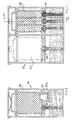
- Figures 5 and 6 are vertical sections of a container 60 having two distinct compartments 62 and 63 separated by a partition wall 65.
- the container 60 is adapted to contain a cartridge 64 full of ink of one color, e.g. black, in the compartment 62 and a cartridge 66 containing ink of three different colors in the compartment 63.
- Each ink impregnates a corresponding spongy body 67a, 67b, 67c, 67d (Fig. 5).
- the cartridge 66 is divided into three distinct chambers 66a, 66b, 66c separated by two walls 68.
- the base wall 69 is provided with three holes, one for each chamber 66, through which three corresponding capillary elements 70, 71, 72 supply ink to the spongy bodies 67, each with the appropriate color of ink.
- the three corresponding colored inks are contained in respective distinct compartments 75, 76, 77 disposed in the lower wall 78 of the container 60.
- the cartridge 64 is supplied in an analogous manner by a capillary element 80 which is immersed in a reservoir 82 containing black ink.
- the container 60 is closed at the top by a cover 84 which can be made in one piece or can be divided into two separate parts, one for each compartment 62 and 63.
- Figs. 7 and 8 show a container 86 embodying the invention which is adapted to supply and hold two different integral heads 87 and 88.
- the integral head 87 not shown in the drawing is similar to that 40 of Fig. 4 and is used for one single color, while the head 88 contains different inks in three compartments of the reservoir 89, these supplying three corresponding printing heads e.g. 88b fixed to the reservoir 89 (Fig. 8).
- Fig. 9 shows a container 90 embodying the invention which is adapted to contain four distinct integral heads 91 for four inks of different colors.
- the four heads 91 are identical to one another and to the head 40 of Fig. 4.
- Fig. 10 is a vertical section along the line X-X of Fig. 9 of one of the integral heads 91.
- the container 90 is divided into four independent compartments 92 separated from one another by means of partition walls 93. Ribs 94 and 96 similar to the analogous ribs 29 and 30 of Figures 1-4 are present in each compartment to support the integral heads 91.
- the container 90 is closed at the top by a removable airtight cover 97.
- the cover 97 can be divided into two or four separate parts so that two compartments or one single compartment can be uncovered at a time.
- the container of Fig. 9 can be modified in a simple manner so that it can accommodate four cartridges identical to one another and similar to the cartridge 32 of Fig. 1 or the cartridge 64 of Fig. 6, each filled with ink of a different color, the part 99 being made flat relative to the wall 18, as in Fig. 1.
- the containers of Figures 3, 8 and 10 can be adapted to accommodate a cartridge 105/support 106 group, as illustrated in Fig. 11.
- the cartridge 105 is similar to the one designated 32 in Fig. 1, while the support 106 consists of a parallelepipedal container 108 open towards the top and comprising lateral walls 110 having internal dimensions such that it can accommodate the cartridge 105.
- the container 108 On one base wall 112 and in the vicinity of a wall 110', the container 108 comprises a printing head 114 comprising a chamber 118 for the ink to supply a plate 120 carrying the printing nozzles 122.
- the plate 120 is of the type already described hereinabove with reference to Fig. 4.
- the chamber 118 communicates with the nozzles 122 via a passage 126.
- the support 106 is provided with coupling elements 128 for removably mounting the cartridge/support group on the carriage (not shown) of a printer.
- a multi-track flat cable 130 electrically connected via one end to the plate 120 is fixed to the outer face of the wall 110' in order to apply electric pulses to the plate 120 for the expulsion of drops of ink through the nozzles 122.
- a capillary element 134 is fixed to the support 106 on the interior of the wall 112 in correspondence with the chamber 118.
- the element 134 projects towards the interior of the container 108 so as to penetrate into a hole 136 in the cartridge 105 in order to come into contact with a spongy body 103 contained in the cartridge 105 and impregnated with ink.
- the element 134 transfers the ink from the sponge 103 into the chamber 118 still full of ink by capillarity, and supplies the nozzles 122.
- the cartridge 105 When the cartridge 105 is empty, it can be removed from the support 106 and can be introduced into a container 10 (Fig. 1) to be refilled with ink and to be kept full for subsequent use.
- the entire cartridge/support group 105-106 can be removed from the carriage of the printer and can be introduced into a modified container based on that of Figures 3, 8, and 10, as already explained hereinabove.
- the cartridge 105 mounted on the appropriate support 106 can be kept ready for use for an indefinite period of time.
- Figs. 12-14 show another device embodying the invention, adapted to contain and hold two cartridges of reduced size referred to as lap-top cartridges.
- a container 140 is divided internally by a partition wall 142 into a lower chamber 144 and an upper part 146.
- the upper part 146 is in turn divided into two compartments 147 and 148 by a wall 150.
- a cartridge 152 of reduced size compared, e.g. to the cartridge 32 of Fig. 1 is placed in the compartment 147.
- the cartridge 152 rests on two supporting ribs 155, 156 disposed on the wall 142.
- a capillary element 160 is fixed to the wall 142 and projects partially via one end 162 into the compartment 147 so as to contact, via a hole 153 formed in one wall of the cartridge 152, a spongy body 154 contained in its interior. In this manner, the ink contained in the lower chamber 144 supplies the cartridge 152 by capillary action via the element 160.
- the compartment 148 is completely sealed off both with respect to the lower chamber 144 and with respect to the exterior, so that it can house a cartridge 152' (Fig. 13) inserted into a support 170 carrying an ink-jet printing head 172 of a type similar to the head 42, 46 described with reference to Fig. 4.
- a cover 145 closes the upper opening of the container 140 in an airtight manner once a sealed cartridge 152 has been inserted into the compartment 147 and a cartridge 152' with the appropriate support 170 has been inserted into the compartment 148.
- the support 170 comprises a chamber 174 for supplying ink to the head 172 which communicates hydraulically with the cartridge 152' by means of a porous capillary element 176 emerging from the chamber 174.
- the capillary element 176 penetrates into the cartridge 152' through a hole 177 (Fig. 14) in order to contact the spongy body 154, which draws in the ink to supply the chamber 174.
- the compartment 147 moreover communicates with the lower chamber 144 by means of a duct 158 provided at the hole 177 of the cartridge 152 (Fig, 14) in order to keep that portion of sponge 154 appearing through the hole 177 in a damp environment and to keep the pressure in the interior of the cartridge 152 constant.
- the cartridge 152 is fixed firmly in its seat formed by the ribs 155, 156 by means of a leaf spring 163 fixed to the cover 145. Moreover, the cartridge 152 is pressed against the duct 158 by an elastic member 166 disposed between one lateral wall 141 and the cartridge 152 along the axis and on the opposite side with respect to the duct 158.
Applications Claiming Priority (2)
| Application Number | Priority Date | Filing Date | Title |
|---|---|---|---|
| ITTO921045A IT1258135B (it) | 1992-12-28 | 1992-12-28 | Dispositivo per conservare e mantenere rifornite d'inchiostro le cartucce di una stampante a getto d'inchiostro. |
| ITTO921045 | 1992-12-28 |
Publications (3)
| Publication Number | Publication Date |
|---|---|
| EP0605183A2 true EP0605183A2 (fr) | 1994-07-06 |
| EP0605183A3 EP0605183A3 (fr) | 1994-08-17 |
| EP0605183B1 EP0605183B1 (fr) | 1997-06-04 |
Family
ID=11410949
Family Applications (1)
| Application Number | Title | Priority Date | Filing Date |
|---|---|---|---|
| EP93310396A Expired - Lifetime EP0605183B1 (fr) | 1992-12-28 | 1993-12-21 | Dispositif pour tenir des cartouches et les maintenir en état d'alimentation d'encre pour une imprimante à jet d'encre |
Country Status (4)
| Country | Link |
|---|---|
| EP (1) | EP0605183B1 (fr) |
| JP (1) | JP3419524B2 (fr) |
| DE (1) | DE69311285T2 (fr) |
| IT (1) | IT1258135B (fr) |
Cited By (34)
| Publication number | Priority date | Publication date | Assignee | Title |
|---|---|---|---|---|
| EP0727314A2 (fr) * | 1995-02-17 | 1996-08-21 | Fuji Xerox Co., Ltd. | Système d'alimentation en encre |
| EP0728586A2 (fr) * | 1995-02-21 | 1996-08-28 | Fuji Xerox Co., Ltd. | Système d'alimentation en encre et dispositif d'enregistrement |
| DE29507743U1 (de) * | 1995-05-10 | 1996-09-12 | Pelikan Produktions Ag | Druckkopf für einen Ink-Jet-Printer |
| FR2731652A1 (fr) * | 1995-03-13 | 1996-09-20 | Seiko Epson Corp | Boite de stockage d'unite d'impression a jet d'encre |
| GB2299972A (en) * | 1995-04-21 | 1996-10-23 | Seiko Epson Corp | An ink tank cartridge and method and apparatus for refilling an ink tank cartridge |
| EP0748692A1 (fr) * | 1995-06-13 | 1996-12-18 | Canon Kabushiki Kaisha | Réservoir d'encre et son procédé de fabrication, cartouche d'encre et dispositif à jet d'encre |
| EP0749838A1 (fr) * | 1995-06-21 | 1996-12-27 | Canon Kabushiki Kaisha | Réservoir d'encre pour appareil enregistreur à jet d'encre |
| US5657058A (en) * | 1990-01-30 | 1997-08-12 | Seiko Epson Corporation | Ink-jet recording apparatus and ink tank cartridge therefor |
| EP0699532A3 (fr) * | 1994-08-31 | 1998-03-18 | Canon Kabushiki Kaisha | Méthode et appareil de recharge en encre pour réservoir à encre |
| US5745139A (en) * | 1994-12-12 | 1998-04-28 | Brother Kogyo Kabushiki Kaisha | Ink feed connecting member |
| US5856838A (en) * | 1996-02-21 | 1999-01-05 | Fuji Xerox Co., Ltd. | Ink supply device and recording apparatus |
| NL1008040C2 (nl) * | 1998-01-16 | 1999-07-19 | Oce Tech Bv | Inktvoorraadhouder geschikt voor aansluiting op een inkjetprintkop alsmede een systeem van een dergelijke inktvoorraadhouder en een inkjetprintkop. |
| US5959647A (en) * | 1996-04-29 | 1999-09-28 | Hewlett-Packard Company | Technique for converting single cartridge monochrome printer to multi-cartridge color inkjet printer |
| US6000790A (en) * | 1993-08-19 | 1999-12-14 | Fuji Xerox Co., Ltd. | Ink supply device |
| US6007191A (en) * | 1993-08-19 | 1999-12-28 | Fuji Xerox Co., Ltd. | Ink supply unit |
| US6024442A (en) * | 1995-11-08 | 2000-02-15 | Canon Kabushiki Kaisha | Ink refilling method and apparatus, ink container refilled therewith and ink jet apparatus comprising ink refilling apparatus |
| US6059403A (en) * | 1995-12-21 | 2000-05-09 | Pelikan Produktions Ag | Liquid cartridge and print head for an ink-jet printer |
| WO2001019615A1 (fr) * | 1999-09-13 | 2001-03-22 | Fullmark Private Limited | Procede et dispositif permettant de recharger une cartouche d'encre equipee d'une tete d'impression |
| US6238042B1 (en) | 1994-09-16 | 2001-05-29 | Seiko Epson Corporation | Ink cartridge for ink jet printer and method of charging ink into said cartridge |
| US6247803B1 (en) | 1983-10-13 | 2001-06-19 | Seiko Epson Corporation | Ink jet recording apparatus and method for replenishing ink in the tank cartridge |
| US6250745B1 (en) * | 1996-08-21 | 2001-06-26 | Seiko Epson Corporation | Ink cartridge for printers |
| EP1114725A2 (fr) * | 2000-01-05 | 2001-07-11 | Hewlett-Packard Company, A Delaware Corporation | Dispositif d'écriture à jet d'encre avec couvercle en deux parties |
| WO2001049496A1 (fr) * | 2000-01-05 | 2001-07-12 | Hewlett-Packard Company | Techniques d'adaptation d'une cartouche pour jet d'encre de petite taille en vue d'une utilisation dans un chariot dimensionne pour une cartouche de grande taille |
| US6276785B1 (en) | 1983-10-13 | 2001-08-21 | Seiko Epson Corporation | Ink-supplied printer head and ink container |
| WO2004091919A1 (fr) | 2003-04-17 | 2004-10-28 | Telecom Italia S.P.A. | Poste de stockage et de remplissage d'encre pour cartouche de tete d'impression |
| WO2004091918A1 (fr) * | 2003-04-17 | 2004-10-28 | Telecom Italia S.P.A. | Dispositif de stockage et de remplissage simultane d'une cartouche d'une tete d'impression en couleur avec des encres de differentes couleurs |
| DE102006057090A1 (de) * | 2006-12-04 | 2008-06-05 | Pelikan Hardcopy Production Ag | Vorrichtung zur Wiederbefüllung einer Tintenpatrone für einen Tintenstrahldrucker |
| DE19710755B4 (de) * | 1996-03-14 | 2008-10-02 | Hewlett-Packard Development Co., L.P., Houston | Tintennachfüllsystem |
| DE102007040108A1 (de) * | 2007-08-06 | 2009-02-12 | Pelikan Hardcopy Production Ag | Vorrichtung zur Wiederbefüllung einer Tintenpatrone für einen Tintenstrahldrucker |
| EP2022637A3 (fr) * | 2007-08-06 | 2010-07-21 | Pelikan Hardcopy Production AG | Dispositif de nouveau remplissage d'une cartouche d'encre pour une imprimante à jet d'encre |
| CN102371767A (zh) * | 2010-08-12 | 2012-03-14 | 珠海纳思达企业管理有限公司 | 一种负压式墨盒填充装置、系统及填充方法 |
| EP2657032A4 (fr) * | 2010-12-22 | 2017-01-11 | Zhuhai Ninestar Management Co., Ltd | Dispositif et système de remplissage de cartouche d'encre et procédé associé |
| WO2019151971A1 (fr) * | 2018-01-30 | 2019-08-08 | Hewlett-Packard Development Company, L.P. | Système d'impression |
| US11518577B2 (en) | 2017-09-12 | 2022-12-06 | Canon Kabushiki Kaisha | Liquid container and manufacturing method of the same |
Families Citing this family (1)
| Publication number | Priority date | Publication date | Assignee | Title |
|---|---|---|---|---|
| JPH10193636A (ja) * | 1996-11-18 | 1998-07-28 | Mitsubishi Pencil Co Ltd | 補充用インクカートリッジ |
Citations (4)
| Publication number | Priority date | Publication date | Assignee | Title |
|---|---|---|---|---|
| US4791438A (en) * | 1987-10-28 | 1988-12-13 | Hewlett-Packard Company | Balanced capillary ink jet pen for ink jet printing systems |
| EP0320165A1 (fr) * | 1987-12-03 | 1989-06-14 | Hewlett-Packard Company | Dispositif d'écriture par jet d'encre muni d'un réservoir d'encre et de moyens de distribution |
| EP0322131A1 (fr) * | 1987-12-21 | 1989-06-28 | Hewlett-Packard Company | Dispositif d'alimentation d'encre hors-bord et procédé de commande d'une imprimante à jet d'encre |
| EP0496642A2 (fr) * | 1991-01-25 | 1992-07-29 | Canon Kabushiki Kaisha | Appareil d'enregistrement à jet d'encre et cartouche amovible à jet d'encre |
-
1992
- 1992-12-28 IT ITTO921045A patent/IT1258135B/it active IP Right Grant
-
1993
- 1993-12-21 DE DE69311285T patent/DE69311285T2/de not_active Expired - Lifetime
- 1993-12-21 EP EP93310396A patent/EP0605183B1/fr not_active Expired - Lifetime
- 1993-12-28 JP JP33596793A patent/JP3419524B2/ja not_active Expired - Lifetime
Patent Citations (4)
| Publication number | Priority date | Publication date | Assignee | Title |
|---|---|---|---|---|
| US4791438A (en) * | 1987-10-28 | 1988-12-13 | Hewlett-Packard Company | Balanced capillary ink jet pen for ink jet printing systems |
| EP0320165A1 (fr) * | 1987-12-03 | 1989-06-14 | Hewlett-Packard Company | Dispositif d'écriture par jet d'encre muni d'un réservoir d'encre et de moyens de distribution |
| EP0322131A1 (fr) * | 1987-12-21 | 1989-06-28 | Hewlett-Packard Company | Dispositif d'alimentation d'encre hors-bord et procédé de commande d'une imprimante à jet d'encre |
| EP0496642A2 (fr) * | 1991-01-25 | 1992-07-29 | Canon Kabushiki Kaisha | Appareil d'enregistrement à jet d'encre et cartouche amovible à jet d'encre |
Cited By (57)
| Publication number | Priority date | Publication date | Assignee | Title |
|---|---|---|---|---|
| US6276785B1 (en) | 1983-10-13 | 2001-08-21 | Seiko Epson Corporation | Ink-supplied printer head and ink container |
| US6247803B1 (en) | 1983-10-13 | 2001-06-19 | Seiko Epson Corporation | Ink jet recording apparatus and method for replenishing ink in the tank cartridge |
| US5657058A (en) * | 1990-01-30 | 1997-08-12 | Seiko Epson Corporation | Ink-jet recording apparatus and ink tank cartridge therefor |
| US6045207A (en) * | 1990-01-30 | 2000-04-04 | Seiko Epson Corporation | Ink-jet recording apparatus and ink tank cartridge therefor |
| US6007191A (en) * | 1993-08-19 | 1999-12-28 | Fuji Xerox Co., Ltd. | Ink supply unit |
| US6000790A (en) * | 1993-08-19 | 1999-12-14 | Fuji Xerox Co., Ltd. | Ink supply device |
| US6116722A (en) * | 1994-08-31 | 2000-09-12 | Canon Kabushiki Kaisha | Ink jet ink refilling method and apparatus |
| EP0699532A3 (fr) * | 1994-08-31 | 1998-03-18 | Canon Kabushiki Kaisha | Méthode et appareil de recharge en encre pour réservoir à encre |
| US6238042B1 (en) | 1994-09-16 | 2001-05-29 | Seiko Epson Corporation | Ink cartridge for ink jet printer and method of charging ink into said cartridge |
| US5745139A (en) * | 1994-12-12 | 1998-04-28 | Brother Kogyo Kabushiki Kaisha | Ink feed connecting member |
| EP0727314A3 (fr) * | 1995-02-17 | 1998-03-11 | Fuji Xerox Co., Ltd. | Système d'alimentation en encre |
| EP0727314A2 (fr) * | 1995-02-17 | 1996-08-21 | Fuji Xerox Co., Ltd. | Système d'alimentation en encre |
| EP0728586A2 (fr) * | 1995-02-21 | 1996-08-28 | Fuji Xerox Co., Ltd. | Système d'alimentation en encre et dispositif d'enregistrement |
| US5821965A (en) * | 1995-02-21 | 1998-10-13 | Fuji Xerox Co., Ltd. | Ink supply unit and recorder |
| EP0728586A3 (fr) * | 1995-02-21 | 1998-04-08 | Fuji Xerox Co., Ltd. | Système d'alimentation en encre et dispositif d'enregistrement |
| FR2731652A1 (fr) * | 1995-03-13 | 1996-09-20 | Seiko Epson Corp | Boite de stockage d'unite d'impression a jet d'encre |
| US5805181A (en) * | 1995-03-13 | 1998-09-08 | Seiko Epson Corporation | Storage case for storing an ink jet printing unit, the ink jet printing unit including an ink jet recording head and cartridge |
| AU695470B2 (en) * | 1995-04-21 | 1998-08-13 | Seiko Epson Corporation | Ink-supplied printer and ink supply tank |
| GB2299972B (en) * | 1995-04-21 | 1998-01-07 | Seiko Epson Corp | Ink-supplied recording apparatus and ink cartridge, and method and apparatus for refilling an ink tank cartridge for use therewith |
| GB2299972A (en) * | 1995-04-21 | 1996-10-23 | Seiko Epson Corp | An ink tank cartridge and method and apparatus for refilling an ink tank cartridge |
| US5767881A (en) * | 1995-05-10 | 1998-06-16 | Pelikan Produktions Ag | Print head for an ink jet printer |
| FR2733937A1 (fr) * | 1995-05-10 | 1996-11-15 | Pelikan Produktions Ag | Tete d'impression pour une imprimante a jet d'encre |
| DE29507743U1 (de) * | 1995-05-10 | 1996-09-12 | Pelikan Produktions Ag | Druckkopf für einen Ink-Jet-Printer |
| CN1053147C (zh) * | 1995-06-13 | 2000-06-07 | 佳能株式会社 | 油墨盒、油墨盒制造方法、喷墨卡盒及喷墨装置 |
| EP0748692A1 (fr) * | 1995-06-13 | 1996-12-18 | Canon Kabushiki Kaisha | Réservoir d'encre et son procédé de fabrication, cartouche d'encre et dispositif à jet d'encre |
| US6183075B1 (en) | 1995-06-13 | 2001-02-06 | Canon Kabushiki Kaisha | Ink container, manufacturing method therefor, ink jet cartridge and ink jet apparatus |
| EP0749838A1 (fr) * | 1995-06-21 | 1996-12-27 | Canon Kabushiki Kaisha | Réservoir d'encre pour appareil enregistreur à jet d'encre |
| US5912689A (en) * | 1995-06-21 | 1999-06-15 | Canon Kabushiki Kaisha | Ink tank mounted on an ink jet apparatus |
| US6024442A (en) * | 1995-11-08 | 2000-02-15 | Canon Kabushiki Kaisha | Ink refilling method and apparatus, ink container refilled therewith and ink jet apparatus comprising ink refilling apparatus |
| US6338552B1 (en) | 1995-11-08 | 2002-01-15 | Canon Kabushiki Kaisha | Ink refilling method and apparatus, ink container refilled therewith and ink jet apparatus comprising ink refilling apparatus |
| US6059403A (en) * | 1995-12-21 | 2000-05-09 | Pelikan Produktions Ag | Liquid cartridge and print head for an ink-jet printer |
| US5856838A (en) * | 1996-02-21 | 1999-01-05 | Fuji Xerox Co., Ltd. | Ink supply device and recording apparatus |
| DE19710755B4 (de) * | 1996-03-14 | 2008-10-02 | Hewlett-Packard Development Co., L.P., Houston | Tintennachfüllsystem |
| US5959647A (en) * | 1996-04-29 | 1999-09-28 | Hewlett-Packard Company | Technique for converting single cartridge monochrome printer to multi-cartridge color inkjet printer |
| US6250745B1 (en) * | 1996-08-21 | 2001-06-26 | Seiko Epson Corporation | Ink cartridge for printers |
| NL1008040C2 (nl) * | 1998-01-16 | 1999-07-19 | Oce Tech Bv | Inktvoorraadhouder geschikt voor aansluiting op een inkjetprintkop alsmede een systeem van een dergelijke inktvoorraadhouder en een inkjetprintkop. |
| US6296352B1 (en) | 1998-01-16 | 2001-10-02 | Oce-Technologies B.V. | Ink supply container suitable for connection to an inkjet printhead |
| EP0931659A1 (fr) * | 1998-01-16 | 1999-07-28 | Océ-Technologies B.V. | Réservoir d'alimentation en encre pouvant être raccordé à une imprimante à jet d'encre, système contenant un tel réservoir et tête d'impression à jet d'encre |
| WO2001019615A1 (fr) * | 1999-09-13 | 2001-03-22 | Fullmark Private Limited | Procede et dispositif permettant de recharger une cartouche d'encre equipee d'une tete d'impression |
| EP1114725A2 (fr) * | 2000-01-05 | 2001-07-11 | Hewlett-Packard Company, A Delaware Corporation | Dispositif d'écriture à jet d'encre avec couvercle en deux parties |
| WO2001049496A1 (fr) * | 2000-01-05 | 2001-07-12 | Hewlett-Packard Company | Techniques d'adaptation d'une cartouche pour jet d'encre de petite taille en vue d'une utilisation dans un chariot dimensionne pour une cartouche de grande taille |
| EP1114725A3 (fr) * | 2000-01-05 | 2001-11-07 | Hewlett-Packard Company, A Delaware Corporation | Dispositif d'écriture à jet d'encre avec couvercle en deux parties |
| AU768894B2 (en) * | 2000-01-05 | 2004-01-08 | Hewlett-Packard Development Company, L.P. | Techniques for adapting a small form factor ink-jet cartridge for use in a carriage sized for a large form factor cartridge |
| US7273273B2 (en) | 2003-04-17 | 2007-09-25 | Telecom Italia S.P.A. | Device for storing and simultaneously refilling with different color inks a cartridge of a color printhead |
| US7513611B2 (en) | 2003-04-17 | 2009-04-07 | Telecom Italia S.P.A. | Storage and ink refilling station for a cartridge of a printhead |
| WO2004091918A1 (fr) * | 2003-04-17 | 2004-10-28 | Telecom Italia S.P.A. | Dispositif de stockage et de remplissage simultane d'une cartouche d'une tete d'impression en couleur avec des encres de differentes couleurs |
| CN100404265C (zh) * | 2003-04-17 | 2008-07-23 | 意大利电信股份公司 | 用于贮存彩色印刷头墨盒和同时向该墨盒补充不同颜色墨水的装置 |
| CN100404266C (zh) * | 2003-04-17 | 2008-07-23 | 意大利电信股份公司 | 贮存印刷头的墨盒且向该墨盒补充墨水的站 |
| WO2004091919A1 (fr) | 2003-04-17 | 2004-10-28 | Telecom Italia S.P.A. | Poste de stockage et de remplissage d'encre pour cartouche de tete d'impression |
| DE102006057090A1 (de) * | 2006-12-04 | 2008-06-05 | Pelikan Hardcopy Production Ag | Vorrichtung zur Wiederbefüllung einer Tintenpatrone für einen Tintenstrahldrucker |
| DE102007040108A1 (de) * | 2007-08-06 | 2009-02-12 | Pelikan Hardcopy Production Ag | Vorrichtung zur Wiederbefüllung einer Tintenpatrone für einen Tintenstrahldrucker |
| EP2022637A3 (fr) * | 2007-08-06 | 2010-07-21 | Pelikan Hardcopy Production AG | Dispositif de nouveau remplissage d'une cartouche d'encre pour une imprimante à jet d'encre |
| CN102371767A (zh) * | 2010-08-12 | 2012-03-14 | 珠海纳思达企业管理有限公司 | 一种负压式墨盒填充装置、系统及填充方法 |
| CN102371767B (zh) * | 2010-08-12 | 2014-06-25 | 珠海纳思达企业管理有限公司 | 一种负压式墨盒填充装置、系统及填充方法 |
| EP2657032A4 (fr) * | 2010-12-22 | 2017-01-11 | Zhuhai Ninestar Management Co., Ltd | Dispositif et système de remplissage de cartouche d'encre et procédé associé |
| US11518577B2 (en) | 2017-09-12 | 2022-12-06 | Canon Kabushiki Kaisha | Liquid container and manufacturing method of the same |
| WO2019151971A1 (fr) * | 2018-01-30 | 2019-08-08 | Hewlett-Packard Development Company, L.P. | Système d'impression |
Also Published As
| Publication number | Publication date |
|---|---|
| JPH071744A (ja) | 1995-01-06 |
| DE69311285T2 (de) | 1998-01-08 |
| IT1258135B (it) | 1996-02-20 |
| EP0605183B1 (fr) | 1997-06-04 |
| ITTO921045A0 (it) | 1992-12-28 |
| DE69311285D1 (de) | 1997-07-10 |
| ITTO921045A1 (it) | 1994-06-28 |
| JP3419524B2 (ja) | 2003-06-23 |
| EP0605183A3 (fr) | 1994-08-17 |
Similar Documents
| Publication | Publication Date | Title |
|---|---|---|
| EP0605183B1 (fr) | Dispositif pour tenir des cartouches et les maintenir en état d'alimentation d'encre pour une imprimante à jet d'encre | |
| US6733115B2 (en) | Ink-jet pen with two-part lid and techniques for filling | |
| EP0408241B1 (fr) | Tête d'impression pour imprimante par jet d'encre thermique | |
| US5408256A (en) | Refillable color ink jet cartridge and method for making said cartridge | |
| US6145974A (en) | Ink-supplied printer head and ink container | |
| US5495877A (en) | Device, kit, and process for filling of a print cartridge of an ink jet printer | |
| US6247803B1 (en) | Ink jet recording apparatus and method for replenishing ink in the tank cartridge | |
| US7540599B2 (en) | Bridging wick and method for an inkjet printhead | |
| GB2293141A (en) | Multi-chambered ink cartridge for ink jet printer. | |
| US4148041A (en) | Method and apparatus for purging air from jet ink writing systems | |
| JP4252243B2 (ja) | フォームファクタの小さいインクジェットカートリッジをフォームファクタの大きいカートリッジ用のサイズのキャリッジでの使用に備えて適合させる技術 | |
| JP3066425B2 (ja) | シ―ルを有するインクジェットのインクカ―トリッジ | |
| EP0568124B1 (fr) | Méthode et support pour recharger des cartouches d'encre utilisées dans les appareils d'impression à jet d'encre et similaires | |
| KR100350172B1 (ko) | 잉크공급프린터및잉크공급탱크 | |
| JPH04156339A (ja) | インクカートリッジ | |
| US6474798B1 (en) | Ink supplied printer head and ink container | |
| US5642144A (en) | Rechargeable pen for printer | |
| WO2001019615A1 (fr) | Procede et dispositif permettant de recharger une cartouche d'encre equipee d'une tete d'impression | |
| WO1997016314A1 (fr) | Cartouche a encre avec une efficacite volumetrique amelioree | |
| JP2002036580A (ja) | インクジェット記録装置、及びインクカートリッジ | |
| JPH09240001A (ja) | インク再充填装置およびそのインク再充填方法 | |
| WO1997016314A9 (fr) | Cartouche a encre avec une efficacite volumetrique amelioree | |
| JP2001001682A (ja) | インキタンク | |
| AU705309B2 (en) | An ink replenishment pack for ink supplied recording apparatus | |
| JP2024059413A (ja) | 画像形成装置及びカートリッジ支持部材 |
Legal Events
| Date | Code | Title | Description |
|---|---|---|---|
| PUAI | Public reference made under article 153(3) epc to a published international application that has entered the european phase |
Free format text: ORIGINAL CODE: 0009012 |
|
| PUAL | Search report despatched |
Free format text: ORIGINAL CODE: 0009013 |
|
| AK | Designated contracting states |
Kind code of ref document: A2 Designated state(s): DE FR GB |
|
| AK | Designated contracting states |
Kind code of ref document: A3 Designated state(s): DE FR GB |
|
| 17P | Request for examination filed |
Effective date: 19950120 |
|
| GRAG | Despatch of communication of intention to grant |
Free format text: ORIGINAL CODE: EPIDOS AGRA |
|
| 17Q | First examination report despatched |
Effective date: 19960722 |
|
| GRAH | Despatch of communication of intention to grant a patent |
Free format text: ORIGINAL CODE: EPIDOS IGRA |
|
| GRAH | Despatch of communication of intention to grant a patent |
Free format text: ORIGINAL CODE: EPIDOS IGRA |
|
| GRAA | (expected) grant |
Free format text: ORIGINAL CODE: 0009210 |
|
| AK | Designated contracting states |
Kind code of ref document: B1 Designated state(s): DE FR GB |
|
| REF | Corresponds to: |
Ref document number: 69311285 Country of ref document: DE Date of ref document: 19970710 |
|
| ET | Fr: translation filed | ||
| PLBE | No opposition filed within time limit |
Free format text: ORIGINAL CODE: 0009261 |
|
| STAA | Information on the status of an ep patent application or granted ep patent |
Free format text: STATUS: NO OPPOSITION FILED WITHIN TIME LIMIT |
|
| 26N | No opposition filed | ||
| REG | Reference to a national code |
Ref country code: GB Ref legal event code: 732E |
|
| REG | Reference to a national code |
Ref country code: FR Ref legal event code: TP |
|
| REG | Reference to a national code |
Ref country code: GB Ref legal event code: IF02 |
|
| PGFP | Annual fee paid to national office [announced via postgrant information from national office to epo] |
Ref country code: GB Payment date: 20121227 Year of fee payment: 20 |
|
| PGFP | Annual fee paid to national office [announced via postgrant information from national office to epo] |
Ref country code: FR Payment date: 20130110 Year of fee payment: 20 |
|
| PGFP | Annual fee paid to national office [announced via postgrant information from national office to epo] |
Ref country code: DE Payment date: 20121231 Year of fee payment: 20 |
|
| REG | Reference to a national code |
Ref country code: DE Ref legal event code: R071 Ref document number: 69311285 Country of ref document: DE |
|
| REG | Reference to a national code |
Ref country code: GB Ref legal event code: PE20 Expiry date: 20131220 |
|
| PG25 | Lapsed in a contracting state [announced via postgrant information from national office to epo] |
Ref country code: DE Free format text: LAPSE BECAUSE OF EXPIRATION OF PROTECTION Effective date: 20131224 Ref country code: GB Free format text: LAPSE BECAUSE OF EXPIRATION OF PROTECTION Effective date: 20131220 |