EP0605116B1 - Depolarisator für optische Komponenten in optischen Übertragungssystemen - Google Patents
Depolarisator für optische Komponenten in optischen Übertragungssystemen Download PDFInfo
- Publication number
- EP0605116B1 EP0605116B1 EP93309761A EP93309761A EP0605116B1 EP 0605116 B1 EP0605116 B1 EP 0605116B1 EP 93309761 A EP93309761 A EP 93309761A EP 93309761 A EP93309761 A EP 93309761A EP 0605116 B1 EP0605116 B1 EP 0605116B1
- Authority
- EP
- European Patent Office
- Prior art keywords
- optical
- signal
- doped
- depolarizer
- optical fiber
- Prior art date
- Legal status (The legal status is an assumption and is not a legal conclusion. Google has not performed a legal analysis and makes no representation as to the accuracy of the status listed.)
- Expired - Lifetime
Links
- 230000003287 optical effect Effects 0.000 title claims description 58
- 230000005540 biological transmission Effects 0.000 title description 8
- 230000010287 polarization Effects 0.000 claims description 42
- 230000001419 dependent effect Effects 0.000 claims description 33
- UYAHIZSMUZPPFV-UHFFFAOYSA-N erbium Chemical compound [Er] UYAHIZSMUZPPFV-UHFFFAOYSA-N 0.000 claims description 24
- 229910052691 Erbium Inorganic materials 0.000 claims description 22
- 230000002269 spontaneous effect Effects 0.000 claims description 17
- 239000013307 optical fiber Substances 0.000 claims description 16
- 229910052779 Neodymium Inorganic materials 0.000 claims description 3
- QEFYFXOXNSNQGX-UHFFFAOYSA-N neodymium atom Chemical compound [Nd] QEFYFXOXNSNQGX-UHFFFAOYSA-N 0.000 claims description 3
- 239000000835 fiber Substances 0.000 description 27
- 238000005259 measurement Methods 0.000 description 7
- 238000010521 absorption reaction Methods 0.000 description 5
- 238000006243 chemical reaction Methods 0.000 description 3
- 230000015556 catabolic process Effects 0.000 description 2
- 238000006731 degradation reaction Methods 0.000 description 2
- 230000000694 effects Effects 0.000 description 2
- 230000005283 ground state Effects 0.000 description 2
- 238000003780 insertion Methods 0.000 description 2
- 230000037431 insertion Effects 0.000 description 2
- 238000000034 method Methods 0.000 description 2
- 230000002411 adverse Effects 0.000 description 1
- 230000003321 amplification Effects 0.000 description 1
- 230000001186 cumulative effect Effects 0.000 description 1
- 238000010586 diagram Methods 0.000 description 1
- 230000004927 fusion Effects 0.000 description 1
- 238000009434 installation Methods 0.000 description 1
- 239000000463 material Substances 0.000 description 1
- 238000003199 nucleic acid amplification method Methods 0.000 description 1
- 238000011144 upstream manufacturing Methods 0.000 description 1
Images

Classifications
-
- G—PHYSICS
- G01—MEASURING; TESTING
- G01M—TESTING STATIC OR DYNAMIC BALANCE OF MACHINES OR STRUCTURES; TESTING OF STRUCTURES OR APPARATUS, NOT OTHERWISE PROVIDED FOR
- G01M11/00—Testing of optical apparatus; Testing structures by optical methods not otherwise provided for
- G01M11/30—Testing of optical devices, constituted by fibre optics or optical waveguides
- G01M11/33—Testing of optical devices, constituted by fibre optics or optical waveguides with a light emitter being disposed at one fibre or waveguide end-face, and a light receiver at the other end-face
- G01M11/337—Testing of optical devices, constituted by fibre optics or optical waveguides with a light emitter being disposed at one fibre or waveguide end-face, and a light receiver at the other end-face by measuring polarization dependent loss [PDL]
-
- G—PHYSICS
- G01—MEASURING; TESTING
- G01M—TESTING STATIC OR DYNAMIC BALANCE OF MACHINES OR STRUCTURES; TESTING OF STRUCTURES OR APPARATUS, NOT OTHERWISE PROVIDED FOR
- G01M11/00—Testing of optical apparatus; Testing structures by optical methods not otherwise provided for
- G01M11/30—Testing of optical devices, constituted by fibre optics or optical waveguides
- G01M11/33—Testing of optical devices, constituted by fibre optics or optical waveguides with a light emitter being disposed at one fibre or waveguide end-face, and a light receiver at the other end-face
- G01M11/333—Testing of optical devices, constituted by fibre optics or optical waveguides with a light emitter being disposed at one fibre or waveguide end-face, and a light receiver at the other end-face using modulated input signals
-
- H—ELECTRICITY
- H04—ELECTRIC COMMUNICATION TECHNIQUE
- H04B—TRANSMISSION
- H04B10/00—Transmission systems employing electromagnetic waves other than radio-waves, e.g. infrared, visible or ultraviolet light, or employing corpuscular radiation, e.g. quantum communication
- H04B10/25—Arrangements specific to fibre transmission
- H04B10/2507—Arrangements specific to fibre transmission for the reduction or elimination of distortion or dispersion
- H04B10/2572—Arrangements specific to fibre transmission for the reduction or elimination of distortion or dispersion due to forms of polarisation-dependent distortion other than PMD
Definitions
- This invention relates generally to a depolarizer. More particularly, this invention relates to a depolarizer within a test set for measuring polarization dependent loss of optical components.
- Polarization Dependent Loss can be defined as the variation in insertion loss as a function of the polarization of an input signal to an optical device.
- PDL Polarization Dependent Loss
- the polarization dependent loss of the various optical components or devices can result in signal degradation.
- polarization dependent loss measurements of optical devices are obtainable to an accuracy 0.01 dB.
- This invention is directed toward solving this problem.
- an unpumped erbium doped fiber can convert received polarized energy such as that which is generated by a laser into unpolarized amplified spontaneous emission of a longer wavelength if the fiber is of sufficient length to absorb the received polarized signal. It is our understanding that the conversion of polarized light into unpolarized light occurs for the following reason.
- polarized light which lies within the erbium absorption band is received by a length of unpumped erbium doped fiber, the received light acts as a pump and excites the erbium atoms. These excited atoms return to the ground state by emitting lower energy photons which have a longer wavelength. If the emitted photons are still within the erbium absorption band, the process is repeated. Thus, amplified spontaneous emission is generated at successively longer wavelengths and the unpumped doped fiber becomes a depolarizer. When the fiber has a length which is long enough to completely absorb the received signal, longer wavelength unpolarized amplified spontaneous emission is generated.
- the inventive depolarizer is used in a test set to measure accurately the polarization dependent loss of an optical device. Previous efforts to measure polarization dependent loss of passive optical devices have been limited because of the polarization dependent loss which is present in the measuring equipment. With a test set which includes the inventive depolarizer, the polarization dependent loss of the measuring equipment never enters into the measured result.
- Polarization dependent loss of optical components in optical transmission systems is a primary cause of signal degradation.
- a polarization dependent loss of 0.01 dB per optical component can adversely affect the quality of the signal.
- a signal source 22 which can be a DFB laser generates optical energy that lies within the absorption bandwidth of an erbium doped fiber 36 located downstream of an optical component 34 that is to be tested and upstream of a test or power meter 38.
- the stability of the laser can effect the precision of the test results.
- the laser 22 can have an integral cooler and can be coupled to a modulator 20.
- the modulator modulates the laser at 10MHz to reduce the coherence length of the laser 22. With this arrangement the laser stability obtained was found to be less than 0.002 dB variation in a 2-minute interval.
- the DFB laser 22 is spliced to an optical isolator 24 which, in turn, is spliced to a 1.5nm bandpass angle tuned interference filter 26.
- the filter 26 reduces the amplified spontaneous emission from the laser. In those instances where the DFB laser does not have long wavelength amplified spontaneous emission, the filter 26 can be eliminated.
- the filter 26 is spliced to a second optical isolator 28 which, in turn, is spliced to an optical tap 30 having two outputs.
- One output of the tap is connected directly to power meter 38 which can be a Hewlett Packard 8153A power meter.
- the signal which is applied from the optical tap directly to the power meter is the reference signal. Measurements with the power meter are made in a ratio mode using the reference signal to account for slow drifts in the components of the test apparatus.
- the other output of the optical tap is connected to an all fiber manual polarization controller 32. Bend loss associated with adjustments of the polarization controller is eliminated by using optical fibers that have small mode field diameters.
- the output of the all fiber manual polarization controller is spliced to the optical component 34 that is to be tested.
- the output of the optical component that is to be tested is spliced to the unpumped erbium doped fiber 36 which operates as a depolarizer.
- the output of the depolarizer 36 is spliced to the power meter 38.
- the depolarizer 36 converts the received polarized signal to amplified spontaneous emission which is not polarized.
- the power meter receives and measures unpolarized light to determine the polarization dependent loss of the optical component being tested. As the light which is received by the power meter is not polarized, the polarization dependent loss of the power meter does not influence the measurement obtained.
- the use of the depolarizer 36 to eliminate the power meter polarization dependent loss in a test set is a major improvement over the prior art.
- the depolarizer here disclosed is an unpumped erbium doped fiber.
- erbium doped fiber is used as an optical amplifier in fiber transmission systems. Amplification of signals between 1530 and 1565 nm occurs when the erbium doped fiber is pumped at either 1480 nm or 980 nm. With no input signal, a pumped erbium doped fiber produces unpolarized Amplified Spontaneous Emission over a broad range of from 1500 nm to 1600 nm.
- the effectiveness of the erbium doped optical fiber depolarizer was examined.
- the test set was first characterized without a depolarizer. With no optical component connected, the residual polarization dependent loss was found to be 0.01 dB. But, with the unpumped erbium doped fiber depolarizer in place, the residual polarization dependent loss was found to be 0.001 dB. It is to be noted that to obtain this value, care was exercised in the installation of the test set fibers since polarization dependent loss of 0.005 dB can be obtained with subtle bends in the fibers. In this instance, measurements were made at both 1558 nm and 1480 nm, with identical results.
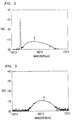
- FIG. 2 there is illustrated the partial conversion of a polarized optical signal into unpolarized amplified spontaneous emission for a short length of erbium doped fiber.
- the sharp spike is the received polarized signal and curve A is the generated amplified spontaneous emission.
- FIG. 3 there is illustrated the complete conversion of a received polarized optical signal into unpolarized amplified spontaneous emission for a length of unpumped doped optical fiber where the input signal is completely depolarized. In FIG. 3 there is no spike input signal because it has been completely absorbed. Curve A is the generated amplified spontaneous emission.
- an unpumped erbium doped fiber is included as a depolarizer of a test set for measuring the polarization dependent loss of an optical device. While the embodiment disclosed in FIG. 1 illustrates the use of an erbium doped fiber as the depolarizer, it is to be understood that the optical fibers can be doped with other material such as neodymium which can be used for other wavelengths.
- the depolarizer is described in combination with a test set for measuring the insertion loss of an optical component, it is obvious that the unpumped optical fiber can be used as a depolarizer for other applications such as, for example, in fiber gyros which use depolarized light.
Landscapes
- Physics & Mathematics (AREA)
- Optics & Photonics (AREA)
- Chemical & Material Sciences (AREA)
- Analytical Chemistry (AREA)
- General Physics & Mathematics (AREA)
- Electromagnetism (AREA)
- Engineering & Computer Science (AREA)
- Computer Networks & Wireless Communication (AREA)
- Signal Processing (AREA)
- Lasers (AREA)
- Optical Communication System (AREA)
- Optical Fibers, Optical Fiber Cores, And Optical Fiber Bundles (AREA)
Claims (10)
- Depolarisator umfassend:
eine ungepumpte dotierte optische Faser (36) von einer Länge, die ausreicht, um ein angelegtes polarisiertes Signal zu absorbieren, um aus dem angelegten Signal unpolarisierte verstärkte spontane Emission mit längerer Wellenlänge zu erzeugen. - Depolarisator nach Anspruch 1, bei welchem die dotierte optische Faser von einer Länge ist, die ausreicht, um das angelegte Signal vollständig zu absorbieren.
- Depolarisator nach Anspruch 1, bei welchem die optische Faser mit Erbium dotiert ist.
- Depolarisator nach Anspruch 1, bei welchem die optische Faser mit Neodymium dotiert ist.
- Prüfeinrichtung zum Messen polarisationsabhängiger Verluste einer optischen Komponente, umfassend:eine Signalquelle (22) zum Erzeugen eines polarisierten Signals,einen optischen Isolator (24), der angeschlossen ist, um das Signal von der Signalquelle zu empfangen,einen optischen Abgriff (30), der angeschlossen ist, um das optische Signal von dem optischen Isolator in ein erstes und ein zweites Signal zu teilen,eine Polarisationssteuereinrichtung (32), die angeschlossen ist, um das erste Signal von dem optischen Abgriff zu empfangen,eine ungepumpte dotierte optische Faser (36), die angeschlossen ist, um das erste Signal von der Polarisationssteuereinrichtung zu empfangen, wobei die ungepumpte dotierte optische Faser eine Länge hat, die ausreicht, um das empfangene erste Signal vollständig zu absorbieren und aus dem empfangenen ersten Signal unpolarisierte verstärkte spontane Emission mit längerer Wellenlänge zu erzeugen,eine Leistungsmesseinrichtung (38), die angeschlossen ist, um das zweite Signal von dem optischen Abgriff und die unpolarisierte verstärkte spontane Emission von der ungepumpten dotierten optischen Faser zu empfangen, undeine Einrichtung zum örtlichen Festlegen einer optischen Komponente, deren polarisationsabhängige Verluste zwischen der Polarisationssteuereinrichtung und der ungepumpten dotierten optischen Faser zu messen ist.
- Prüfeinrichtung nach Anspruch 5, bei welcher die ungepumpte dotierte optische Faser mit Erbium dotiert ist.
- Prüfeinrichtung nach Anspruch 5, bei welcher die ungepumpte dotierte optische Faser mit Neodymium dotiert ist.
- Prüfeinrichtung nach Anspruch 6, bei welcher die Signalquelle einen Laser umfaßt.
- Prüfeinrichtung nach Anspruch 8, ferner umfassend: einen Modulator (20), der angeschlossen ist, um den Laser zu modulieren.
- Prüfeinrichtung nach Anspruch 9, ferner umfassend: ein Interferenzfilter (26), das zwischen dem optischen Isolator und dem optischen Abgriff angeordnet ist, und einen zweiten optischen Isolator (28), der zwischen dem Interferenzfilter und dem optischen Abgriff angeordnet ist.
Applications Claiming Priority (2)
| Application Number | Priority Date | Filing Date | Title |
|---|---|---|---|
| US07/999,080 US5337375A (en) | 1992-12-31 | 1992-12-31 | Depolarizer using unpumped, doped optical fiber and method using same |
| US999080 | 1992-12-31 |
Publications (3)
| Publication Number | Publication Date |
|---|---|
| EP0605116A2 EP0605116A2 (de) | 1994-07-06 |
| EP0605116A3 EP0605116A3 (de) | 1995-02-01 |
| EP0605116B1 true EP0605116B1 (de) | 1997-04-09 |
Family
ID=25545871
Family Applications (1)
| Application Number | Title | Priority Date | Filing Date |
|---|---|---|---|
| EP93309761A Expired - Lifetime EP0605116B1 (de) | 1992-12-31 | 1993-12-06 | Depolarisator für optische Komponenten in optischen Übertragungssystemen |
Country Status (4)
| Country | Link |
|---|---|
| US (1) | US5337375A (de) |
| EP (1) | EP0605116B1 (de) |
| JP (1) | JP2719494B2 (de) |
| DE (1) | DE69309637T2 (de) |
Cited By (1)
| Publication number | Priority date | Publication date | Assignee | Title |
|---|---|---|---|---|
| CN110380331A (zh) * | 2019-07-22 | 2019-10-25 | 华东师范大学 | 一种缩短脉冲并获得可调皮秒脉冲的方法 |
Families Citing this family (14)
| Publication number | Priority date | Publication date | Assignee | Title |
|---|---|---|---|---|
| JP3284507B2 (ja) * | 1993-06-28 | 2002-05-20 | 富士通株式会社 | 光通信システム用の光送信装置及び光増幅装置 |
| US5408545A (en) * | 1994-01-19 | 1995-04-18 | Dicon Fiberoptics | Depolarizer for fiber optic applications and method using same |
| US5461415A (en) * | 1994-03-15 | 1995-10-24 | International Business Machines Corporation | Look-ahead scheduling to support video-on-demand applications |
| US5453779A (en) * | 1994-03-15 | 1995-09-26 | International Business Machines Corporation | Scheduling policies with grouping for providing VCR control functions in a video server |
| JPH08263438A (ja) * | 1994-11-23 | 1996-10-11 | Xerox Corp | ディジタルワークの配給及び使用制御システム並びにディジタルワークへのアクセス制御方法 |
| KR0150486B1 (ko) * | 1994-12-07 | 1998-12-01 | 양승택 | 단일 펌프 광원을 이용한 파장가변형 다파장 광섬유 레이저 구도 |
| JPH11289130A (ja) * | 1998-04-03 | 1999-10-19 | Furukawa Electric Co Ltd:The | 外部共振器型レーザ |
| US6147757A (en) * | 1999-02-23 | 2000-11-14 | Alliance Fiber Optics Products, Inc. | Apparatus and method employing depolarization to eliminate effect of polarization dependent loss |
| US6396965B1 (en) * | 2000-11-22 | 2002-05-28 | Tektronix, Inc. | Twisting fiber depolarizer |
| KR100380255B1 (ko) * | 2001-03-16 | 2003-04-18 | 도남시스템주식회사 | 반복적인 고속 편광 스크램블링을 이용한 편광의존성 손실측정장치 및 방법 |
| AU2002325885A1 (en) | 2002-02-28 | 2003-09-29 | Agilent Technologies, Inc. | Determining measuring uncertainty or error of a pdl-tester |
| CN105865498B (zh) * | 2016-03-28 | 2017-11-21 | 太原理工大学 | 基于自激发布里渊激光器的高灵敏分布式光纤传感系统 |
| CN115145063A (zh) * | 2021-03-30 | 2022-10-04 | Tdk株式会社 | 光学器件 |
| CN115441947B (zh) * | 2022-11-07 | 2023-03-24 | 济南量子技术研究院 | 基于时差测量的光纤实地链路色散测量系统及方法 |
Family Cites Families (18)
| Publication number | Priority date | Publication date | Assignee | Title |
|---|---|---|---|---|
| US4606605A (en) * | 1984-06-29 | 1986-08-19 | At&T Bell Laboratories | Optical fiber having in-line polarization filter |
| JPS61112123A (ja) * | 1984-11-06 | 1986-05-30 | Nippon Telegr & Teleph Corp <Ntt> | 偏波解消器 |
| US4711525A (en) * | 1985-05-08 | 1987-12-08 | Litton Systems, Inc. | Polarizing optical fiber with absorbing jacket |
| FR2588093B1 (fr) * | 1985-09-27 | 1987-11-20 | Thomson Csf | Polariseur par absorption differentielle, son procede de realisation et dispositif mettant en oeuvre ledit procede |
| GB8622745D0 (en) * | 1986-09-22 | 1986-10-29 | Plessey Co Plc | Bistable optical device |
| GB8724736D0 (en) * | 1987-10-22 | 1987-11-25 | British Telecomm | Optical fibre |
| DE3741455A1 (de) * | 1987-12-08 | 1989-06-22 | Standard Elektrik Lorenz Ag | Optischer isolator |
| US4964131A (en) * | 1988-12-16 | 1990-10-16 | The Board Of Trustees Of The Leland Standford Junior University | Broadband optical fiber laser |
| FR2659755B1 (fr) * | 1990-03-16 | 1992-05-29 | Alcatel Nv | Amplificateur optique a fibre dopee a l'erbium. |
| JP2687680B2 (ja) * | 1990-05-18 | 1997-12-08 | 日本電気株式会社 | 光ファイバ増幅装置 |
| US5117303A (en) * | 1990-08-23 | 1992-05-26 | At&T Bell Laboratories | Method of operating concatenated optical amplifiers |
| US5132976A (en) * | 1991-05-28 | 1992-07-21 | At&T Bell Laboratories | Electrically tunable fiber ring laser |
| US5216728A (en) * | 1991-06-14 | 1993-06-01 | Corning Incorporated | Optical fiber amplifier with filter |
| US5268910A (en) * | 1991-07-18 | 1993-12-07 | General Instrument Corporation | Superluminescent optical source |
| US5131069A (en) * | 1991-08-12 | 1992-07-14 | Corning Incorporated | Fiber amplifier having modified gain spectrum |
| US5218652A (en) * | 1991-08-29 | 1993-06-08 | Minnesota Mining And Manufacturing Company | Depolarizer for electromagnetic radiation |
| JP2677726B2 (ja) * | 1991-09-20 | 1997-11-17 | 富士通株式会社 | 光送信機 |
| EP0543061B1 (de) * | 1991-11-20 | 1998-07-15 | Hamamatsu Photonics K.K. | Lichtverstärkungspolarisator |
-
1992
- 1992-12-31 US US07/999,080 patent/US5337375A/en not_active Expired - Lifetime
-
1993
- 1993-12-06 EP EP93309761A patent/EP0605116B1/de not_active Expired - Lifetime
- 1993-12-06 DE DE69309637T patent/DE69309637T2/de not_active Expired - Fee Related
- 1993-12-24 JP JP5346001A patent/JP2719494B2/ja not_active Expired - Fee Related
Cited By (1)
| Publication number | Priority date | Publication date | Assignee | Title |
|---|---|---|---|---|
| CN110380331A (zh) * | 2019-07-22 | 2019-10-25 | 华东师范大学 | 一种缩短脉冲并获得可调皮秒脉冲的方法 |
Also Published As
| Publication number | Publication date |
|---|---|
| US5337375A (en) | 1994-08-09 |
| EP0605116A3 (de) | 1995-02-01 |
| EP0605116A2 (de) | 1994-07-06 |
| DE69309637D1 (de) | 1997-05-15 |
| JP2719494B2 (ja) | 1998-02-25 |
| JPH077208A (ja) | 1995-01-10 |
| DE69309637T2 (de) | 1997-10-16 |
Similar Documents
| Publication | Publication Date | Title |
|---|---|---|
| EP0605116B1 (de) | Depolarisator für optische Komponenten in optischen Übertragungssystemen | |
| Baney et al. | Theory and measurement techniques for the noise figure of optical amplifiers | |
| US6519378B1 (en) | Method and apparatus for implementation of an unpolarized monochromatic light source | |
| CA2117826C (en) | System and method for measuring polarization dependent loss | |
| US6008935A (en) | Optical amplifier and optical amplifier gain control method and apparatus | |
| US20080296481A1 (en) | Chirp measurement method, chirp measurement apparatus and their application | |
| US6016213A (en) | Method and apparatus for optical amplifier gain and noise figure measurement | |
| JPH07301580A (ja) | ノイズレベルの測定方法 | |
| EP0570151B1 (de) | Optischer Sender mit Lichtsignal von geringem Polarisationsgrad und optische entpolarisierende Schaltung | |
| EP0586103B1 (de) | Messung eines Parameters eines optischen Verstärkers | |
| US5436751A (en) | Analog optical transmission system and optical fiber amplifier | |
| US5295015A (en) | Optical amplifying apparatus | |
| CN104979750B (zh) | 全光纤化半导体激光器稳频装置 | |
| US5574534A (en) | Apparatus for determining noise factor of optical amplifier | |
| Havlis et al. | Bidirectional optical amplifier delivering high gain | |
| JP3180746B2 (ja) | 光増幅装置並びに光増幅器利得制御方法及び装置 | |
| JP6731684B2 (ja) | 光ファイバ出力光源装置 | |
| CN112104415A (zh) | 一种采用edfa放大装置检测瑞利散射信号强度的系统 | |
| US5700949A (en) | Optical receiver calibration based on a relative intensity noise standard | |
| JP2001196668A (ja) | 光 源 | |
| SU1019343A1 (ru) | Оптоэлектронное измерительное устройство | |
| Jungerman et al. | EDFA Noise Figure Standard | |
| JPH01142435A (ja) | 後方散乱光測定装置 | |
| JP2713672B2 (ja) | 光増幅器雑音指数測定装置 | |
| JPS61102081A (ja) | 半導体レ−ザの周波数安定化方法 |
Legal Events
| Date | Code | Title | Description |
|---|---|---|---|
| PUAI | Public reference made under article 153(3) epc to a published international application that has entered the european phase |
Free format text: ORIGINAL CODE: 0009012 |
|
| AK | Designated contracting states |
Kind code of ref document: A2 Designated state(s): DE FR GB |
|
| PUAL | Search report despatched |
Free format text: ORIGINAL CODE: 0009013 |
|
| AK | Designated contracting states |
Kind code of ref document: A3 Designated state(s): DE FR GB |
|
| 17P | Request for examination filed |
Effective date: 19950720 |
|
| GRAG | Despatch of communication of intention to grant |
Free format text: ORIGINAL CODE: EPIDOS AGRA |
|
| 17Q | First examination report despatched |
Effective date: 19960820 |
|
| GRAH | Despatch of communication of intention to grant a patent |
Free format text: ORIGINAL CODE: EPIDOS IGRA |
|
| GRAH | Despatch of communication of intention to grant a patent |
Free format text: ORIGINAL CODE: EPIDOS IGRA |
|
| GRAA | (expected) grant |
Free format text: ORIGINAL CODE: 0009210 |
|
| AK | Designated contracting states |
Kind code of ref document: B1 Designated state(s): DE FR GB |
|
| REF | Corresponds to: |
Ref document number: 69309637 Country of ref document: DE Date of ref document: 19970515 |
|
| ET | Fr: translation filed | ||
| PLBE | No opposition filed within time limit |
Free format text: ORIGINAL CODE: 0009261 |
|
| STAA | Information on the status of an ep patent application or granted ep patent |
Free format text: STATUS: NO OPPOSITION FILED WITHIN TIME LIMIT |
|
| 26N | No opposition filed | ||
| REG | Reference to a national code |
Ref country code: GB Ref legal event code: IF02 |
|
| PGFP | Annual fee paid to national office [announced via postgrant information from national office to epo] |
Ref country code: GB Payment date: 20071218 Year of fee payment: 15 |
|
| PGFP | Annual fee paid to national office [announced via postgrant information from national office to epo] |
Ref country code: DE Payment date: 20071221 Year of fee payment: 15 |
|
| PGFP | Annual fee paid to national office [announced via postgrant information from national office to epo] |
Ref country code: FR Payment date: 20071217 Year of fee payment: 15 |
|
| GBPC | Gb: european patent ceased through non-payment of renewal fee |
Effective date: 20081206 |
|
| REG | Reference to a national code |
Ref country code: FR Ref legal event code: ST Effective date: 20090831 |
|
| PG25 | Lapsed in a contracting state [announced via postgrant information from national office to epo] |
Ref country code: DE Free format text: LAPSE BECAUSE OF NON-PAYMENT OF DUE FEES Effective date: 20090701 |
|
| PG25 | Lapsed in a contracting state [announced via postgrant information from national office to epo] |
Ref country code: GB Free format text: LAPSE BECAUSE OF NON-PAYMENT OF DUE FEES Effective date: 20081206 |
|
| PG25 | Lapsed in a contracting state [announced via postgrant information from national office to epo] |
Ref country code: FR Free format text: LAPSE BECAUSE OF NON-PAYMENT OF DUE FEES Effective date: 20081231 |