EP0604321A1 - Device for filling and venting a fuel tank - Google Patents
Device for filling and venting a fuel tank Download PDFInfo
- Publication number
- EP0604321A1 EP0604321A1 EP93403160A EP93403160A EP0604321A1 EP 0604321 A1 EP0604321 A1 EP 0604321A1 EP 93403160 A EP93403160 A EP 93403160A EP 93403160 A EP93403160 A EP 93403160A EP 0604321 A1 EP0604321 A1 EP 0604321A1
- Authority
- EP
- European Patent Office
- Prior art keywords
- filling
- membrane
- tube
- tank
- venting
- Prior art date
- Legal status (The legal status is an assumption and is not a legal conclusion. Google has not performed a legal analysis and makes no representation as to the accuracy of the status listed.)
- Granted
Links
Images


Classifications
-
- B—PERFORMING OPERATIONS; TRANSPORTING
- B60—VEHICLES IN GENERAL
- B60K—ARRANGEMENT OR MOUNTING OF PROPULSION UNITS OR OF TRANSMISSIONS IN VEHICLES; ARRANGEMENT OR MOUNTING OF PLURAL DIVERSE PRIME-MOVERS IN VEHICLES; AUXILIARY DRIVES FOR VEHICLES; INSTRUMENTATION OR DASHBOARDS FOR VEHICLES; ARRANGEMENTS IN CONNECTION WITH COOLING, AIR INTAKE, GAS EXHAUST OR FUEL SUPPLY OF PROPULSION UNITS IN VEHICLES
- B60K15/00—Arrangement in connection with fuel supply of combustion engines or other fuel consuming energy converters, e.g. fuel cells; Mounting or construction of fuel tanks
- B60K15/03—Fuel tanks
- B60K15/035—Fuel tanks characterised by venting means
- B60K15/03519—Valve arrangements in the vent line
-
- B—PERFORMING OPERATIONS; TRANSPORTING
- B60—VEHICLES IN GENERAL
- B60K—ARRANGEMENT OR MOUNTING OF PROPULSION UNITS OR OF TRANSMISSIONS IN VEHICLES; ARRANGEMENT OR MOUNTING OF PLURAL DIVERSE PRIME-MOVERS IN VEHICLES; AUXILIARY DRIVES FOR VEHICLES; INSTRUMENTATION OR DASHBOARDS FOR VEHICLES; ARRANGEMENTS IN CONNECTION WITH COOLING, AIR INTAKE, GAS EXHAUST OR FUEL SUPPLY OF PROPULSION UNITS IN VEHICLES
- B60K15/00—Arrangement in connection with fuel supply of combustion engines or other fuel consuming energy converters, e.g. fuel cells; Mounting or construction of fuel tanks
- B60K15/03—Fuel tanks
- B60K15/04—Tank inlets
Definitions
- the present invention relates to a device for filling and ventilating a fuel tank.
- the invention relates more particularly to a device of the type comprising a tubing for filling the tank, the filling orifice is fitted with a plug, a vent pipe, one end of which is arranged inside the tank. at a level located lower than that of an upper bulkhead of the tank, and a valve which cooperates with the other end of the venting duct and which is controlled by the plug to close this other end of the duct vented when the cap is removed so as to provide an expansion capacity at the upper part of the tank delimited by the upper partition and by the maximum filling level of the tank.
- the expansion capacity integrated in the tank allows the liquid fuel contained in the tank to expand without the risk of overflowing, the phenomenon of expansion possibly being due to an increase in the fuel temperature, in particular due to prolonged exposure of the vehicle under the sun.
- the closing valve is controlled by the plug so that, in normal use of the vehicle, that is to say when the plug is screwed onto the filling orifice, the vent pipe opens directly , or indirectly, in the atmosphere while, during the filling phase, its end is closed by the valve in order to avoid excessive filling of the tank, to preserve the expansion capacity.
- the end of the vent pipe opens into a part of the device which communicates with the filling pipe.
- This arrangement is not entirely satisfactory in the as it causes rising fuel vapors which condense in the form of fuel which flows outside the vehicle into the area of the bodywork where the filler cap is located.
- the object of the invention is to propose a filling device which overcomes this drawback.
- the invention provides a filling device of the type mentioned above, said other end of the venting duct opening into a chamber which is leaktightly separated from the filling pipe, and comprising a filling tube.
- the open air which connects the chamber to a fuel vapor filtration device, characterized in that the chamber is partially delimited by a flexible sealing membrane.
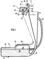
- FIG. 1 shows a fuel tank 10 for a motor vehicle comprising an upper partition 12 and a filling pipe 14 whose filling orifice 16 can be closed by a tight plug (not shown) which cooperates with a seal 18.
- the device for filling and ventilating the tank 10 also comprises a vent pipe 20, also called degassing pipe, which enters an expansion capacity 22 of the fuel volume, arranged at the upper internal part. tank 10.
- a vent pipe 20 also called degassing pipe, which enters an expansion capacity 22 of the fuel volume, arranged at the upper internal part. tank 10.
- the filling device also comprises a discharge conduit 23 opening on the one hand, in the upper part of the filling tube and, on the other hand, in the tank 10 at a level 26 corresponding to the maximum level of fuel 28 when the tank is filled.
- This conduit 23 allows during filling to evacuate the gases contained in the tank 10.
- the upper end 30 of the vent pipe 20 opens into a housing 32, made integrally with the upper part of the filling pipe 14, and the inside 34 of which communicates with the inside of the pipe filling 14.
- the lower rigid partition 36 of the housing 32 into which the upper end 30 of the vent pipe 20 opens has a lever 38 which is pivotally mounted about an axis XX and of which a free end 40 carries a valve d seal 42, produced in the form of an annular bead of elastically deformable material which cooperates with a valve seat 44 formed by the annular radial face of the upper end 30 of the conduit 20.
- the other end 46 of the lever 38 is a heel with the upper face 48 of which is capable of cooperating a portion of the filling plug when the latter is fixed on the filling orifice 16, and this in order to bias the lever 38 in pivoting around the axis XX, clockwise when considering FIG. 1, against a return spring 50 which biases the valve towards its closed position illustrated in FIG. 1.
- the venting duct 20 is closed by the valve 42 which makes it possible to provide the expansion capacity 22 during the filling.
- valve 42 When the user puts the cap back in place, it causes the valve 42 to open by tilting around the axis XX and the communication of the end upper 30 of the vent pipe 20 with the filling pipe 14 is restored.
- the rigid lower partition 36 of the housing 32 which is produced by molding in plastic material with a part of the filling tube 14, comprises a vent tube 52 whose upper end 54 opens into the lower rigid partition 36 and whose other end (not shown) is connected to a fuel vapor filtration device (not shown).
- the open air ducts 20 and tubing 52 open into an intermediate open air chamber 56 which is delimited on the one hand by the internal face 58 of the lower rigid partition 36 and, on the other hand , by a flexible waterproofing membrane 60.
- the flexible membrane has a peripheral edge 62 which is mounted clamped in a complementary groove 64 formed in the internal face 58 of the rigid partition 36 in which it is kept compressed by an elastically deformable blade 66 produced integrally with the rigid partition 36.
- the central portion 68 of the flexible sealing membrane 60 which extends opposite the upper end 30 of the vent pipe 20 comprises, on its internal face 70, the bead of seal 42 which cooperates with the annular seal seat 44.
- the bead 42 is made integrally with the flexible membrane of elastomeric material 60, as well as a hooking button 72 which is formed on the external face 74 of the central portion 68 of the membrane flexible seal 60 and which is fitted elastically into a housing 76 formed in the free end 40 of the control lever 38.
- the valve 42 is thus connected to the control lever 38.
- the membrane 60 In order to give the membrane 60 great flexibility, it has in its central portion a fold 78 and a sleeve 80.
- the upper end 30 of the venting duct 20 communicates, through the intermediate venting chamber 56 with the end 54 of the tube 52 of venting.
- the fuel vapors which rise from the tank via the vent pipe 20 are thus completely isolated from the filling pipe 14 and are directed to the device for filtering the fuel vapors.
- the central portion 68 includes an accordion bellows portion 82 which makes it possible to further improve the elastic deformation faculties of the membrane 60 in its central functional area comprising the closure valve.
- the flexible membrane 60 is of reduced dimensions, and this is due to the fact that the ends 30 and 54 of the duct 20 and tube 52 for venting are coaxial.
- the arrangement of the two ends is obtained, directly from molding, by providing that the tube 52 is arranged transversely relative to the conduit 20 and that it opens into an annular channel 55 which surrounds the upper end 30 of the setting conduit. open air 20.
- valve control member 42 is constituted by an arm 138 which is slidably mounted in the lower rigid partition 36.
- the duct 20 and the vent tube 52 are connected at their ends 30 and 54 which open into the chamber 56, the latter being arranged here on the external face 59 of the rigid partition 36, through passages 84 and 86 formed in the rigid upper partition 37 of the housing 32.
- the passage 84 connects the conduit 20 to its end portion 30 and it is surrounded by the passage 86 which connects the conduit 52 to its end portion 54.
- the ends 30 and 54 open coaxially into the lower face 59 of the lower rigid partition 36.
- FIG. 7 The operation of the embodiment illustrated in FIG. 7 is identical to that of the previous embodiments, the closure of the valve being caused when the user removes the plug 19, the control arm 138 being resiliently biased by the return spring 50 sliding, upwards considering figure 7.
- the flexible sealing membrane independently of the valve 42, the membrane then being in the form of a transverse partition which connects the upper and lower rigid partitions of the housing 32 and which surrounds part of the lever 38 or the sliding arm 138.
- the central portion of the elastic membrane crossed by the arm or the lever can constitute the elastic return means of the latter.
Abstract
Description
La présente invention concerne un dispositif pour le remplissage et l'aération d'un réservoir de carburant.The present invention relates to a device for filling and ventilating a fuel tank.
L'invention concerne plus particulièrement un dispositif du type comportant une tubulure de remplissage du réservoir dont l'orifice de remplissage est équipé d'un bouchon, une conduite de mise à l'air libre dont une extrémité est agencée à l'intérieur du réservoir à un niveau situé plus bas que celui d'une cloison supérieure du réservoir, et un clapet qui coopère avec l'autre extrémité du conduit de mise à l'air libre et qui est commandé par le bouchon pour obturer cette autre extrémité du conduit de mise à l'air libre lorsque le bouchon est ôté de manière à ménager une capacité d'expansion à la partie supérieure du réservoir délimitée par la cloison supérieure et par le niveau maximal de remplissage du réservoir.The invention relates more particularly to a device of the type comprising a tubing for filling the tank, the filling orifice is fitted with a plug, a vent pipe, one end of which is arranged inside the tank. at a level located lower than that of an upper bulkhead of the tank, and a valve which cooperates with the other end of the venting duct and which is controlled by the plug to close this other end of the duct vented when the cap is removed so as to provide an expansion capacity at the upper part of the tank delimited by the upper partition and by the maximum filling level of the tank.
La capacité d'expansion intégrée au réservoir permet au carburant liquide contenu dans le réservoir de se dilater sans risque de débordement, le phénomène de dilatation pouvant être dû à un accroissement de la température du carburant, notamment du fait d'une exposition prolongée du véhicule au soleil.The expansion capacity integrated in the tank allows the liquid fuel contained in the tank to expand without the risk of overflowing, the phenomenon of expansion possibly being due to an increase in the fuel temperature, in particular due to prolonged exposure of the vehicle under the sun.
Le clapet de fermeture est commandé par le bouchon de manière que, en utilisation normale du véhicule, c'est-à-dire lorsque le bouchon est vissé sur l'orifice de remplissage, le conduit de mise à l'air libre débouche, directement, ou indirectement, dans l'atmosphère tandis que, lors de la phase de remplissage, son extrémité est fermée par le clapet afin d'éviter un remplissage excessif du réservoir, pour ménager la capacité d'expansion.The closing valve is controlled by the plug so that, in normal use of the vehicle, that is to say when the plug is screwed onto the filling orifice, the vent pipe opens directly , or indirectly, in the atmosphere while, during the filling phase, its end is closed by the valve in order to avoid excessive filling of the tank, to preserve the expansion capacity.
Parmi les dispositifs de ce type connus de l'état de la technique, l'extrémité du conduit de mise à l'air libre débouche dans une partie du dispositif qui communique avec la conduite de remplissage. Cet agencement n'est pas entièrement satisfaisant dans la mesure où il provoque des remontées de vapeurs de carburant qui se condensent sous la forme de carburant qui s'écoule à l'extérieur du véhicule dans la zone de la carrosserie où est situé le bouchon de remplissage.Among the devices of this type known from the prior art, the end of the vent pipe opens into a part of the device which communicates with the filling pipe. This arrangement is not entirely satisfactory in the as it causes rising fuel vapors which condense in the form of fuel which flows outside the vehicle into the area of the bodywork where the filler cap is located.
L'invention a pour but de proposer un dispositif de remplissage qui remédie à cet inconvénient.The object of the invention is to propose a filling device which overcomes this drawback.
Par ailleurs, les véhicules modernes sont équipés d'un dispositif de filtration des vapeurs de carburant auquel il est nécessaire de pouvoir relier de manière simple et fiable ladite autre extrémité du conduit de mise à l'air libre.Furthermore, modern vehicles are equipped with a fuel vapor filtration device to which it is necessary to be able to connect in a simple and reliable manner said other end of the vent pipe.
Dans ce but, l'invention propose un dispositif de remplissage du type mentionné précédemment, ladite autre extrémité du conduit de mise à l'air libre débouchant dans une chambre séparée de manière étanche de la conduite de remplissage, et comportant un tube de mise à l'air libre qui relie la chambre à un dispositif de filtration des vapeurs de carburant, caractérisé en ce que la chambre est délimitée en partie par une membrane souple d'étanchéité.To this end, the invention provides a filling device of the type mentioned above, said other end of the venting duct opening into a chamber which is leaktightly separated from the filling pipe, and comprising a filling tube. the open air which connects the chamber to a fuel vapor filtration device, characterized in that the chamber is partially delimited by a flexible sealing membrane.
Selon d'autres caractéristiques de l'invention :
- la portion de la membrane souple qui s'étend en vis-à-vis de ladite autre extrémité du conduit de mise à l'air libre porte, sur sa face interne, le clapet ;
- la face externe de ladite portion de la membrane souple d'étanchéité est reliée à un mécanisme de commande des déplacements du clapet ;
- le mécanisme de commande comporte au moins un bras de commande dont l'extrémité libre est reliée à la face externe de ladite portion de la membrane souple d'étanchéité ;
- la face externe de ladite portion de la membrane souple d'étanchéité comporte, réalisé venu de matière, un bouton d'accrochage qui est emboîté élastiquement dans un logement complémentaire formé à l'extrémité libre du bras de commande ;
- la chambre est également délimitée par une paroi rigide dans laquelle débouchent ladite autre extrémité du conduit de mise à l'air libre et une extrémité du tube de mise à l'air libre ;
- les extrémités du conduit et du tube de mise à l'air libre qui débouchent dans la paroi rigide sont adjacentes ;
- les extrémités du conduit et du tube de mise à l'air libre qui débouchent dans la paroi rigide sont coaxiales ;
- le bras de commande est monté mobile par rapport à la paroi rigide ;
- le bras mobile est monté articulé sur la paroi rigide ;
- le bras de commande est monté coulissant par rapport à la paroi rigide ;
- la membrane souple d'étanchéité comporte un bord périphérique qui est monté de manière étanche dans une gorge formée dans la cloison rigide ; et
- la portion de la membrane souple qui s'étend en vis-à-vis de ladite autre extrémité du conduit de mise à l'air libre comporte, sur sa face interne et réalisé venu de matière avec la membrane, un bourrelet annulaire d'étanchéité qui coopère avec un siège annulaire d'étanchéité formé à ladite autre extrémité du conduit de mise à l'air libre.
- the portion of the flexible membrane which extends opposite said other end of the vent pipe carries, on its internal face, the valve;
- the outer face of said portion of the flexible sealing membrane is connected to a mechanism for controlling the movements of the valve;
- the control mechanism comprises at least one control arm, the free end of which is connected to the external face of said portion of the flexible sealing membrane;
- the external face of said portion of the flexible sealing membrane comprises, produced integrally, a hooking button which is resiliently fitted in a complementary housing formed at the free end of the control arm;
- the chamber is also delimited by a rigid wall into which open the said other end of the vent pipe and one end of the vent pipe;
- the ends of the duct and the venting tube which open into the rigid wall are adjacent;
- the ends of the duct and the venting tube which open into the rigid wall are coaxial;
- the control arm is mounted movable relative to the rigid wall;
- the movable arm is mounted articulated on the rigid wall;
- the control arm is slidably mounted relative to the rigid wall;
- the flexible sealing membrane has a peripheral edge which is mounted in a sealed manner in a groove formed in the rigid partition; and
- the portion of the flexible membrane which extends opposite said other end of the venting duct comprises, on its internal face and produced integrally with the membrane, an annular sealing bead which cooperates with an annular sealing seat formed at said other end of the venting duct.
D'autres caractéristiques et avantages de l'invention apparaîtront à la lecture de la description détaillée qui va suivre pour la compréhension de laquelle on se reportera aux dessins annexés dans lesquels :
- La figure 1 est une vue schématique en section partielle illustrant un dispositif de remplissage et d'aération selon l'état de la technique ;
- la figure 2 est une vue à plus grande échelle, en section par un plan contenant les axes de la tubulure de remplissage, du conduit de mise à l'air libre et du tube de mise à l'air libre, d'un premier mode de réalisation d'un dispositif de remplissage et d'aération conforme aux enseignements de l'invention qui est illustré en position fermée du clapet ;
- la figure 3 est une vue similaire à celle de la figure 2 dans laquelle le clapet est illustré en position ouverte ;
- la figure 4 est une vue de détail illustrant une variante de réalisation de la membrane souple d'étanchéité des figures 2 et 3 ;
- la figure 5 est une vue similaire à celle de la figure 3 illustrant un second mode de réalisation d'un dispositif de remplissage et d'aération conforme aux enseignements de l'invention ;
- la figure 6 est une vue en section selon la ligne 6-6 de la figure 5 ;
- la figure 7 est une vue similaire à celle de la figure 3 illustrant un troisième mode de réalisation de l'invention ; et
- la figure 8 est une vue en section selon la ligne 8-8 de la figure 7.
- Figure 1 is a schematic view in partial section illustrating a filling and aeration device according to the prior art;
- FIG. 2 is a view on a larger scale, in section through a plane containing the axes of the filling tube, of the vent pipe and of the vent tube, of a first embodiment of a filling and aeration device according to the teachings of the invention which is illustrated in the closed position of the valve;
- Figure 3 is a view similar to that of Figure 2 in which the valve is illustrated in the open position;
- Figure 4 is a detail view illustrating an alternative embodiment of the flexible sealing membrane of Figures 2 and 3;
- Figure 5 is a view similar to that of Figure 3 illustrating a second embodiment of a filling and aeration device according to the teachings of the invention;
- Figure 6 is a sectional view along line 6-6 of Figure 5;
- Figure 7 is a view similar to that of Figure 3 illustrating a third embodiment of the invention; and
- FIG. 8 is a sectional view along line 8-8 of FIG. 7.
On a représenté sur la figure 1 un réservoir 10 de carburant d'un véhicule automobile comportant une cloison supérieure 12 et une tubulure de remplissage 14 dont l'orifice de remplissage 16 peut être fermé par un bouchon étanche (non représenté) qui coopère avec un joint d'étanchéité 18.FIG. 1 shows a
Le dispositif de remplissage et d'aération du réservoir 10 comprend également un conduit de mise à l'air libre 20, également appelé conduit de dégazage, qui pénètre dans une capacité d'expansion 22 du volume du carburant, agencée à la partie interne supérieure du réservoir 10.The device for filling and ventilating the
Le dispositif de remplissage comporte également un conduit de refoulement 23 débouchant d'une part, dans la partie supérieure de la tubulure de remplissage et, d'autre part, dans le réservoir 10 à un niveau 26 correspondant au niveau maximal du carburant 28 lorsque le réservoir est rempli. Ce conduit 23 permet lors du remplissage d'évacuer les gaz contenus dans le réservoir 10.The filling device also comprises a
L'extrémité supérieure 30 du conduit de mise à l'air libre 20 débouche dans un boîtier 32, réalisé venu de matière avec la partie supérieure de la tubulure de remplissage 14, et dont l'intérieur 34 communique avec l'intérieur de la tubulure de remplissage 14.The
La cloison rigide inférieure 36 du boîtier 32 dans laquelle débouche l'extrémité supérieure 30 du conduit de mise à l'air libre 20 comporte un levier 38 qui est monté pivotant autour d'un axe X-X et dont une extrémité libre 40 porte un clapet d'étanchéité 42, réalisé sous la forme d'un bourrelet annulaire en matériau déformable élastiquement qui coopère avec un siège de clapet 44 constitué par la face radiale annulaire de l'extrémité supérieure 30 du conduit 20.The lower
L'autre extrémité 46 du levier 38 est un talon avec la face supérieure 48 duquel est susceptible de coopérer une portion du bouchon de remplissage lorsque ce dernier est fixé sur l'orifice de remplissage 16, et ceci afin de solliciter le levier 38 en pivotement autour de l'axe X-X, dans le sens horaire en considérant la figure 1, à l'encontre d'un ressort de rappel 50 qui sollicite le clapet vers sa position fermée illustrée à la figure 1.The
Lorsque le dispositif est dans sa position de remplissage illustrée à la figure 1 dans laquelle le bouchon est ôté, le conduit de mise à l'air libre 20 est obturé par le clapet 42 ce qui permet de ménager la capacité d'expansion 22 lors du remplissage.When the device is in its filling position illustrated in FIG. 1 in which the plug is removed, the
Lorsque l'utilisateur remet le bouchon en place, il provoque l'ouverture du clapet 42 par basculement autour de l'axe X-X et la communication de l'extrémité supérieure 30 du conduit de mise à l'air libre 20 avec la tubulure de remplissage 14 est rétablie.When the user puts the cap back in place, it causes the
On décrira maintenant un premier mode de réalisation de l'invention illustré aux figures 2 et 3 sur lesquelles les composants identiques ou similaires à ceux de la figure 1 sont désignés par les mêmes chiffres de référence.We will now describe a first embodiment of the invention illustrated in Figures 2 and 3 in which the components identical or similar to those of Figure 1 are designated by the same reference numerals.
La cloison inférieure rigide 36 du boîtier 32, qui est réalisée par moulage en matière plastique avec une partie de la tubulure de remplissage 14, comporte un tube de mise à l'air libre 52 dont l'extrémité supérieure 54 débouche dans la cloison rigide inférieure 36 et dont l'autre extrémité (non représentée) est reliée à un dispositif de filtration des vapeurs de carburant (non représenté).The rigid
Les conduit 20 et tubulure 52 de mise à l'air libre débouchent dans une chambre intermédiaire de mise à l'air libre 56 qui est délimitée d'une part par la face interne 58 de la cloison rigide inférieure 36 et, d'autre part, par un membrane souple d'étanchéité 60.The
La membrane souple comporte un bord périphérique 62 qui est monté serré dans une gorge complémentaire 64 formée dans la face interne 58 de la cloison rigide 36 dans laquelle il est maintenu comprimé par une lame déformable élastiquement 66 réalisée venue de matière avec la cloison rigide 36.The flexible membrane has a
La portion centrale 68 de la membrane souple d'étanchéité 60 qui s'étend en vis-à-vis de l'extrémité supérieure 30 du conduit de mise à l'air libre 20 comporte, sur sa face interne 70, le bourrelet d'étanchéité 42 qui coopère avec le siège annulaire d'étanchéité 44.The
Le bourrelet 42 est réalisé venu de matière avec la membrane souple en matériau élastomère 60, de même qu'un bouton d'accrochage 72 qui est formé sur la face externe 74 de la portion centrale 68 de la membrane souple d'étanchéité 60 et qui est emboîté élastiquement dans un logement 76 formé dans l'extrémité libre 40 du levier de commande 38.The
Le clapet 42 est ainsi relié au levier de commande 38.The
Afin de conférer à la membrane 60 une grande souplesse, celle-ci comporte dans sa portion centrale un pli 78 et un manchon 80.In order to give the
Dans la position fermée du bouchon 19 illustrée à la figure 3, l'extrémité supérieure 30 du conduit de mise à l'air libre 20 communique, à travers la chambre intermédiaire de mise à l'air libre 56 avec l'extrémité 54 du tube 52 de mise à l'air libre.In the closed position of the
Les vapeurs de carburant qui remontent du réservoir par le conduit de mise à l'air libre 20 sont donc ainsi entièrement isolées de la tubulure de remplissage 14 et sont dirigées vers le dispositif de filtration des vapeurs de carburant.The fuel vapors which rise from the tank via the
Dans la variante illustrée à la figure 4, la portion centrale 68 comporte une partie en soufflet en accordéon 82 qui permet d'améliorer encore les facultés de déformation élastique de la membrane 60 dans sa zone fonctionnelle centrale comportant le clapet de fermeture.In the variant illustrated in FIG. 4, the
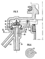
Dans le second mode de réalisation illustré aux figures 5 et 6, la membrane souple 60 est de dimensions réduites, et ceci est dû au fait que les extrémités 30 et 54 du conduit 20 et tube 52 de mise à l'air libre sont coaxiales.In the second embodiment illustrated in FIGS. 5 and 6, the
L'agencement des deux extrémités est obtenu, directement de moulage, en prévoyant que le tube 52 est agencé transversalement par rapport au conduit 20 et qu'il débouche dans un canal annulaire 55 qui entoure l'extrémité supérieure 30 du conduit de mise à l'air libre 20.The arrangement of the two ends is obtained, directly from molding, by providing that the
On décrira maintenant le troisième mode de réalisation illustré aux figures 7 et 8.The third embodiment illustrated in FIGS. 7 and 8 will now be described.
Dans ce mode de réalisation, l'organe de commande du clapet 42 est constitué par un bras 138 qui est monté coulissant dans la cloison rigide inférieure 36.In this embodiment, the
Le conduit 20 et le tube 52 de mise à l'air libre sont reliés à leurs extrémités 30 et 54 qui débouchent dans la chambre 56, cette dernière étant agencée ici sur la face externe 59 de la cloison rigide 36, à travers des passages 84 et 86 formés dans la cloison supérieure rigide 37 du boîtier 32.The
Comme on peut le voir notamment à la figure 8, le passage 84 relie le conduit 20 à sa portion d'extrémité 30 et il est entouré par le passage 86 qui relie le conduit 52 à sa portion d'extrémité 54.As can be seen in particular in FIG. 8, the
Comme dans le cas de la figure 5, les extrémités 30 et 54 débouchent coaxialement dans la face inférieure 59 de la cloison rigide inférieure 36.As in the case of FIG. 5, the ends 30 and 54 open coaxially into the
Le fonctionnement du mode de réalisation illustré à la figure 7 est identique à celui des modes de réalisation précédents, la fermeture du clapet étant provoquée lorsque l'utilisateur ôte le bouchon 19, le bras de commande 138 étant rappelé élastiquement par le ressort de rappel 50 en coulissement, vers le haut en considérant la figure 7.The operation of the embodiment illustrated in FIG. 7 is identical to that of the previous embodiments, the closure of the valve being caused when the user removes the
L'invention n'est pas limitée aux modes de réalisation qui viennent d'être décrits.The invention is not limited to the embodiments which have just been described.
Il est par exemple possible de réaliser la membrane souple d'étanchéité indépendamment du clapet 42, la membrane se présentant alors sous la forme d'une cloison transversale qui relie les cloisons rigides supérieure et inférieure du boîtier 32 et qui entoure une partie du levier 38 ou du bras coulissant 138.It is for example possible to produce the flexible sealing membrane independently of the
Dans un tel mode de réalisation, la portion» centrale de la membrane élastique traversée par le bras ou le levier peut constituer le moyen de rappel élastique de ce dernier.In such an embodiment, the central portion of the elastic membrane crossed by the arm or the lever can constitute the elastic return means of the latter.
Claims (13)
Applications Claiming Priority (2)
| Application Number | Priority Date | Filing Date | Title |
|---|---|---|---|
| FR9215637 | 1992-12-23 | ||
| FR9215637A FR2699462B1 (en) | 1992-12-23 | 1992-12-23 | Fuel tank filling and ventilation device. |
Publications (2)
| Publication Number | Publication Date |
|---|---|
| EP0604321A1 true EP0604321A1 (en) | 1994-06-29 |
| EP0604321B1 EP0604321B1 (en) | 1996-07-17 |
Family
ID=9437050
Family Applications (1)
| Application Number | Title | Priority Date | Filing Date |
|---|---|---|---|
| EP19930403160 Expired - Lifetime EP0604321B1 (en) | 1992-12-23 | 1993-12-23 | Device for filling and venting a fuel tank |
Country Status (4)
| Country | Link |
|---|---|
| EP (1) | EP0604321B1 (en) |
| DE (1) | DE69303699T2 (en) |
| ES (1) | ES2089762T3 (en) |
| FR (1) | FR2699462B1 (en) |
Citations (3)
| Publication number | Priority date | Publication date | Assignee | Title |
|---|---|---|---|---|
| EP0333549A1 (en) * | 1988-03-08 | 1989-09-20 | Paul Journee S.A. | Venting assembly avoiding overfill for a tank |
| GB2218185A (en) * | 1988-04-05 | 1989-11-08 | Kayser A Gmbh & Co Kg | Valve assembly |
| US4941587A (en) * | 1988-06-06 | 1990-07-17 | Honda Giken Kogyo Kabushiki Kaisha | Fuel tank system |
-
1992
- 1992-12-23 FR FR9215637A patent/FR2699462B1/en not_active Expired - Fee Related
-
1993
- 1993-12-23 ES ES93403160T patent/ES2089762T3/en not_active Expired - Lifetime
- 1993-12-23 DE DE1993603699 patent/DE69303699T2/en not_active Expired - Fee Related
- 1993-12-23 EP EP19930403160 patent/EP0604321B1/en not_active Expired - Lifetime
Patent Citations (3)
| Publication number | Priority date | Publication date | Assignee | Title |
|---|---|---|---|---|
| EP0333549A1 (en) * | 1988-03-08 | 1989-09-20 | Paul Journee S.A. | Venting assembly avoiding overfill for a tank |
| GB2218185A (en) * | 1988-04-05 | 1989-11-08 | Kayser A Gmbh & Co Kg | Valve assembly |
| US4941587A (en) * | 1988-06-06 | 1990-07-17 | Honda Giken Kogyo Kabushiki Kaisha | Fuel tank system |
Also Published As
| Publication number | Publication date |
|---|---|
| DE69303699D1 (en) | 1996-08-22 |
| FR2699462A1 (en) | 1994-06-24 |
| EP0604321B1 (en) | 1996-07-17 |
| ES2089762T3 (en) | 1996-10-01 |
| DE69303699T2 (en) | 1996-11-28 |
| FR2699462B1 (en) | 1995-03-10 |
Similar Documents
| Publication | Publication Date | Title |
|---|---|---|
| CA2337219A1 (en) | Filler neck closure assembly | |
| EP1133362B1 (en) | Device for connecting a pump | |
| EP0952376B1 (en) | Double-seat lift valve with inflatable membrane | |
| FR2753138A1 (en) | Filler for motor vehicle fuel tank | |
| EP2216220A1 (en) | Protection for a brake fluid reservoir and reservoir provided with said protection | |
| WO1997025253A1 (en) | Nozzle for dispensing a liquid or pasty material | |
| EP0604321B1 (en) | Device for filling and venting a fuel tank | |
| EP1688332B1 (en) | Pneumatic booster with offset valve seats carried by two sliding sleeves | |
| EP0459866B1 (en) | Device for the ventilation of a fuel tank | |
| EP0604320B1 (en) | Tank filling arrangement associated with a device for the filtration of fuel vapor | |
| EP0516528B1 (en) | Safety valve for the ventilation of a fuel tank of a motor vehicle | |
| FR2625284A1 (en) | Valve for regulating the pressure inside a fuel tank | |
| EP0064427B1 (en) | Pressure regulating valve | |
| FR2676103A3 (en) | PNEUMATIC SPRING OF ADJUSTABLE LENGTH. | |
| FR2762807A1 (en) | Closing end and cap for filling pipe of vehicle fuel tank | |
| FR2766134A1 (en) | Safety air inlet for vehicle fuel tank | |
| FR2669864A1 (en) | Vent valve for a vehicle fuel tank | |
| EP0774569B1 (en) | Cap for a cooling circuit of a motor vehicle | |
| EP3705621B1 (en) | Iron comprising a filling section provided with a seal | |
| FR2675570A1 (en) | Safety device for a closure plug of a heat exchanger | |
| EP0524882B1 (en) | Valved closure cap | |
| EP0116796B1 (en) | Anti-theft cap, particularly for fuel tanks of vehicles | |
| FR2722833A1 (en) | Cooling system for heat engine | |
| FR2509789A1 (en) | Fluid circuit sealing cap - has spring loaded valve in movable assembly opened by striking fixed stop | |
| FR2636573A1 (en) | Device for ventilating a fuel tank, with time delay |
Legal Events
| Date | Code | Title | Description |
|---|---|---|---|
| PUAI | Public reference made under article 153(3) epc to a published international application that has entered the european phase |
Free format text: ORIGINAL CODE: 0009012 |
|
| AK | Designated contracting states |
Kind code of ref document: A1 Designated state(s): DE ES GB IT |
|
| 17P | Request for examination filed |
Effective date: 19941028 |
|
| 17Q | First examination report despatched |
Effective date: 19951004 |
|
| GRAG | Despatch of communication of intention to grant |
Free format text: ORIGINAL CODE: EPIDOS AGRA |
|
| GRAH | Despatch of communication of intention to grant a patent |
Free format text: ORIGINAL CODE: EPIDOS IGRA |
|
| GRAH | Despatch of communication of intention to grant a patent |
Free format text: ORIGINAL CODE: EPIDOS IGRA |
|
| GRAA | (expected) grant |
Free format text: ORIGINAL CODE: 0009210 |
|
| AK | Designated contracting states |
Kind code of ref document: B1 Designated state(s): DE ES GB IT |
|
| REF | Corresponds to: |
Ref document number: 69303699 Country of ref document: DE Date of ref document: 19960822 |
|
| REG | Reference to a national code |
Ref country code: ES Ref legal event code: FG2A Ref document number: 2089762 Country of ref document: ES Kind code of ref document: T3 |
|
| ITF | It: translation for a ep patent filed |
Owner name: SOCIETA' ITALIANA BREVETTI S.P.A. |
|
| GBT | Gb: translation of ep patent filed (gb section 77(6)(a)/1977) |
Effective date: 19960923 |
|
| REG | Reference to a national code |
Ref country code: ES Ref legal event code: FG2A Ref document number: 2089762 Country of ref document: ES Kind code of ref document: T3 |
|
| PLBE | No opposition filed within time limit |
Free format text: ORIGINAL CODE: 0009261 |
|
| STAA | Information on the status of an ep patent application or granted ep patent |
Free format text: STATUS: NO OPPOSITION FILED WITHIN TIME LIMIT |
|
| 26N | No opposition filed | ||
| REG | Reference to a national code |
Ref country code: GB Ref legal event code: IF02 |
|
| PGFP | Annual fee paid to national office [announced via postgrant information from national office to epo] |
Ref country code: ES Payment date: 20081226 Year of fee payment: 16 |
|
| PGFP | Annual fee paid to national office [announced via postgrant information from national office to epo] |
Ref country code: DE Payment date: 20090202 Year of fee payment: 16 |
|
| PGFP | Annual fee paid to national office [announced via postgrant information from national office to epo] |
Ref country code: GB Payment date: 20081229 Year of fee payment: 16 |
|
| PGFP | Annual fee paid to national office [announced via postgrant information from national office to epo] |
Ref country code: IT Payment date: 20081229 Year of fee payment: 16 |
|
| GBPC | Gb: european patent ceased through non-payment of renewal fee |
Effective date: 20091223 |
|
| PG25 | Lapsed in a contracting state [announced via postgrant information from national office to epo] |
Ref country code: DE Free format text: LAPSE BECAUSE OF NON-PAYMENT OF DUE FEES Effective date: 20100701 |
|
| PG25 | Lapsed in a contracting state [announced via postgrant information from national office to epo] |
Ref country code: GB Free format text: LAPSE BECAUSE OF NON-PAYMENT OF DUE FEES Effective date: 20091223 |
|
| REG | Reference to a national code |
Ref country code: ES Ref legal event code: FD2A Effective date: 20110310 |
|
| PG25 | Lapsed in a contracting state [announced via postgrant information from national office to epo] |
Ref country code: IT Free format text: LAPSE BECAUSE OF NON-PAYMENT OF DUE FEES Effective date: 20091223 |
|
| PG25 | Lapsed in a contracting state [announced via postgrant information from national office to epo] |
Ref country code: ES Free format text: LAPSE BECAUSE OF NON-PAYMENT OF DUE FEES Effective date: 20110309 |
|
| PG25 | Lapsed in a contracting state [announced via postgrant information from national office to epo] |
Ref country code: ES Free format text: LAPSE BECAUSE OF NON-PAYMENT OF DUE FEES Effective date: 20091224 |