EP0604253A1 - Vehicle wheel cover - Google Patents
Vehicle wheel cover Download PDFInfo
- Publication number
- EP0604253A1 EP0604253A1 EP93402903A EP93402903A EP0604253A1 EP 0604253 A1 EP0604253 A1 EP 0604253A1 EP 93402903 A EP93402903 A EP 93402903A EP 93402903 A EP93402903 A EP 93402903A EP 0604253 A1 EP0604253 A1 EP 0604253A1
- Authority
- EP
- European Patent Office
- Prior art keywords
- rim
- magnet
- bead
- tab
- hubcap
- Prior art date
- Legal status (The legal status is an assumption and is not a legal conclusion. Google has not performed a legal analysis and makes no representation as to the accuracy of the status listed.)
- Withdrawn
Links
Images

Classifications
-
- B—PERFORMING OPERATIONS; TRANSPORTING
- B60—VEHICLES IN GENERAL
- B60B—VEHICLE WHEELS; CASTORS; AXLES FOR WHEELS OR CASTORS; INCREASING WHEEL ADHESION
- B60B7/00—Wheel cover discs, rings, or the like, for ornamenting, protecting, venting, or obscuring, wholly or in part, the wheel body, rim, hub, or tyre sidewall, e.g. wheel cover discs, wheel cover discs with cooling fins
- B60B7/06—Fastening arrangements therefor
- B60B7/08—Fastening arrangements therefor having gripping elements consisting of formations integral with the cover
Definitions
- the present invention essentially relates to a hubcap capable of being mounted on the steel wheels of a motor vehicle for example.
- Wheel hubcaps are already known which generally consist of a decorative disc, one of the faces of which may have several lugs capable of catching on the wheel rim,
- the lugs are generally held under stress by a metal ring acting as a spring, that is to say pushing the lugs radially and towards the outside to allow their clipping on the wheel rim under the effect of an exerted pressure. on the hubcap.
- a metal ring acting as a spring, that is to say pushing the lugs radially and towards the outside to allow their clipping on the wheel rim under the effect of an exerted pressure. on the hubcap.
- the tabs are compressed between the rim and the metal ring forming a spring.
- the object of the present invention is to remedy in particular the above drawbacks by proposing an improved hubcap and of simple structure, which is not subjected to any stress during storage, but which is stressed only when it is mounted. on the wheel rim, so that the phenomena of paint wear and wear or breakage of the dropouts are advantageously eliminated.
- the subject of the invention is a hubcap for a steel wheel of a motor vehicle in particular and of the type comprising a disc, one of the faces of which has several tabs which can be hooked on the wheel rim, characterized in that each tab is provided with at least one magnet which, in the mounted position of the hubcap, is applied to the inner face of the rim to contribute to the retention of the hubcap on said rim.
- each tab has at its free end a bead or the like which is capable of cooperating with a groove in the inner face of the rim and with which said magnet is associated.
- the magnet is adjacent to the bead and extends radially and externally to the tab at a height less than that of the bead.
- the magnet is embedded in the bead so as to present a part capable of being applied to the bottom of the aforementioned groove.
- the aforementioned magnet is embedded in the bead so as to present a part constituting an end piece of the lug, which end piece is capable of being applied to the bottom of the inner face of the rim.
- the aforementioned magnet is mounted at the free end of each tab or in the vicinity of this free end, this means that each tab may not have a bead at its free end.
- a hubcap in accordance with the principles of this invention essentially comprises a decorative disc 1, the inner face of which carries it a plurality of lugs 2 with each of which is associated, by any appropriate means such as as bonding or overmolding, a magnet 3.
- Each tab 2 has, at its free end, a bead or the like 4 capable of catching in a groove 5 formed in the rim 6 of a steel wheel 7 belonging for example to a motor vehicle.
- the magnet 3 secured to each tab 2 can be associated with the bead 4 at the end of each tab in different ways, as will be described below.
- the magnet is adjacent to the bead 4 and extends radially and towards the outside of the tab 2 at a height which is less than that of the bead 4.
- the magnet 3 is somehow embedded in the bead 4 of each tab 2 so as to have a part or a face 3a capable of being applied to the bottom of the groove 5 in the wheel rim 6.
- the magnet 3 is still embedded in the bead 4 of each tab 2 so as to present a part or a face 3b which here forms in a way a tip of the tab 2, which tip is likely to apply not in the bottom of the groove 5, but on the axial bottom of the inner face of the wheel rim 6.
- the magnet 3 is relatively weak so as not to brake excessively its sliding on the rim during mounting.
- the attachment is carried out simultaneously magnetically by the magnet 3 and mechanically by the bead 4.
- the attachment is effected on the one hand mechanically by the bead 4 cooperating with the groove 5, but also magnetically by the magnet 3 applying to the bottom axial of the inner face of the rim 6.
- the bead 4 can be omitted, so that the attachment can be only magnetic, the tabs 2 ensuring only the centering of the hubcap in the rim 6.
- each leg 2 could be omitted, so that the free end of each leg would simply include a magnet capable of presenting a force. any magnetic device suitable for retaining, and this removably, the hubcap on the wheel 7.
- a wheel cover with magnetic fixing which, during storage, presents no constraint, which is constrained only when it is mounted on the wheel rim, which can easily adapt to the different dimensions of this rim and which eliminates all the problems of wear and even breakage of the legs and also of wear of the paint of the wheels.
- the position of the magnet associated with each leg can be arbitrary, as well as the distribution, the shape and the number of the legs on the hubcap can also be arbitrary depending on the style and technical requirements.
- the invention therefore includes all the technical equivalents of the means described as well as their combinations, if these are carried out according to his spirit.
Abstract
Description
La présente invention a essentiellement pour objet un enjoliveur apte à être monté sur les roues en acier d'un véhicule automobile par exemple.The present invention essentially relates to a hubcap capable of being mounted on the steel wheels of a motor vehicle for example.
On connaît déjà des enjoliveurs de roue se composant d'une manière générale d'un disque décoratif dont l'une des faces peut comporter plusieurs pattes susceptibles de s'accrocher sur la jante de roue,Wheel hubcaps are already known which generally consist of a decorative disc, one of the faces of which may have several lugs capable of catching on the wheel rim,
Les pattes sont généralement maintenues en contrainte par un anneau métallique faisant office de ressort, c'est-à-dire poussant radialement et vers l'extérieur les pattes pour permettre leur clippage sur la jante de roue sous l'effet d'une pression exercée sur l'enjoliveur. Ainsi, après montage, les pattes sont comprimées entre la jante et l'anneau métallique formant ressort.The lugs are generally held under stress by a metal ring acting as a spring, that is to say pushing the lugs radially and towards the outside to allow their clipping on the wheel rim under the effect of an exerted pressure. on the hubcap. Thus, after mounting, the tabs are compressed between the rim and the metal ring forming a spring.
Toutefois, une telle structure d'enjoliveur présente un certain nombre d'inconvénients résultant du montage et du démontage de l'enjoliveur et parmi lesquels il faut citer l'usure de la peinture de roue, l'usure des pattes elles-mêmes, et même parfois la rupture de ces pattes, si elles ont été trop écartées par l'anneau métallique avant montage.However, such a hubcap structure has a certain number of drawbacks resulting from the mounting and dismounting of the hubcap and among which the wear of the wheel paint, the wear of the lugs themselves, and sometimes even the rupture of these legs, if they have been too far apart by the metal ring before mounting.
Aussi, la présente invention a pour but de remédier notamment aux inconvénients ci-dessus en proposant un enjoliveur perfectionné et de structure simple, qui n'est soumis à aucune contrainte lors du stockage, mais qui est mis en contrainte seulement lorsqu'il est monté sur la jante de roue, de sorte que les phénomènes d'usure de la peinture et d'usure ou de rupture des pattes sont avantageusement supprimés.Also, the object of the present invention is to remedy in particular the above drawbacks by proposing an improved hubcap and of simple structure, which is not subjected to any stress during storage, but which is stressed only when it is mounted. on the wheel rim, so that the phenomena of paint wear and wear or breakage of the dropouts are advantageously eliminated.
A cet effet, l'invention a pour objet un enjoliveur pour roue en acier de véhicule automobile en particulier et du type comprenant un disque dont l'une des faces comporte plusieurs pattes pouvant s'accrocher sur la jante de roue, caractérisé en ce que chaque patte est munie d'au moins un aimant qui, en position montée de l'enjoliveur, s'applique sur la face intérieure de la jante pour contribuer à la retenue de l'enjoliveur sur ladite jante.To this end, the subject of the invention is a hubcap for a steel wheel of a motor vehicle in particular and of the type comprising a disc, one of the faces of which has several tabs which can be hooked on the wheel rim, characterized in that each tab is provided with at least one magnet which, in the mounted position of the hubcap, is applied to the inner face of the rim to contribute to the retention of the hubcap on said rim.
Suivant une autre caractéristique de cet enjoliveur, chaque patte comporte à son extrémité libre un bourrelet ou analogue qui est susceptible de coopérer avec une gorge dans la face intérieure de la jante et auquel est associé ledit aimant.According to another characteristic of this hubcap, each tab has at its free end a bead or the like which is capable of cooperating with a groove in the inner face of the rim and with which said magnet is associated.
Suivant un mode de réalisation de l'invention, l'aimant est adjacent au bourrelet et s'étend radialement et extérieurement à la patte suivant une hauteur inférieure à celle du bourrelet.According to one embodiment of the invention, the magnet is adjacent to the bead and extends radially and externally to the tab at a height less than that of the bead.
Suivant un autre mode de réalisation, l'aimant est noyé dans le bourrelet de façon à présenter une partie susceptible de s'appliquer sur le fond de la gorge précitée.According to another embodiment, the magnet is embedded in the bead so as to present a part capable of being applied to the bottom of the aforementioned groove.
Selon encore un autre mode de réalisation, l'aimant précité est noyé dans le bourrelet de façon à présenter une partie constituant un embout de la patte, lequel embout est susceptible de s'appliquer sur le fond de la face intérieure de la jante.According to yet another embodiment, the aforementioned magnet is embedded in the bead so as to present a part constituting an end piece of the lug, which end piece is capable of being applied to the bottom of the inner face of the rim.
Suivant encore une autre caractéristique de cet enjoliveur, l'aimant précité est monté à l'extrémité libre de chaque patte ou au voisinage de cette extrémité libre, ceci signifiant que chaque patte peut ne pas comporter un bourrelet à son extrémité libre.According to yet another characteristic of this hubcap, the aforementioned magnet is mounted at the free end of each tab or in the vicinity of this free end, this means that each tab may not have a bead at its free end.
Mais d'autres caractéristiques et avantages de l'invention apparaîtront mieux dans la description détaillée qui suit et se réfère aux dessins annexés, donnés uniquement à titre d'exemple et dans lesquels :
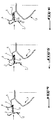
- La figure 1 est une vue en coupe axiale d'un enjoliveur selon l'invention en position montée sur une jante de roue en acier ;
- La figure 2 est une vue partielle encore en coupe axiale d'un autre mode de réalisation de cet enjoliveur ;
- La figure 3 est une vue partielle et en coupe axiale d'encore un autre mode de réalisation de cet enjoliveur.
- Les figures 4 à 6 illustrent successivement les diverses phases de montage de l'enjoliveur représenté sur la figure 1.
- Figure 1 is an axial sectional view of a hubcap according to the invention in position mounted on a steel wheel rim;
- Figure 2 is a partial view still in axial section of another embodiment of this hubcap;
- Figure 3 is a partial view in axial section of yet another embodiment of this hubcap.
- FIGS. 4 to 6 successively illustrate the various stages of mounting the hubcap shown in FIG. 1.
Un enjoliveur conforme aux principes de cette invention, et comme on le voit bien sur les figures 1 à 3, comprend essentiellement un disque décoratif 1 dont la face intérieure la porte une pluralité de pattes 2 à chacune desquelles est associé, par tout moyen approprié tel que collage ou surmoulage, un aimant 3.A hubcap in accordance with the principles of this invention, and as can be seen in FIGS. 1 to 3, essentially comprises a decorative disc 1, the inner face of which carries it a plurality of
Chaque patte 2 comporte, à son extrémité libre, un bourrelet ou analogue 4 susceptible de s'accrocher dans une gorge 5 pratiquée dans la jante 6 d'une roue 7 en acier appartenant par exemple à un véhicule automobile.Each
L'aimant 3 solidaire de chaque patte 2 peut être associé au bourrelet 4 à l'extrémité de chaque patte de différentes manières, comme on le décrira ci-après.The
Suivant le mode de réalisation illustré par la figure 1, l'aimant est adjacent au bourrelet 4 et s'étend radialement et vers l'extérieur de la patte 2 suivant une hauteur qui est inférieure à celle du bourrelet 4.According to the embodiment illustrated in FIG. 1, the magnet is adjacent to the
Dans le mode de réalisation de la figure 2, l'aimant 3 est en quelque sorte noyé dans le bourrelet 4 de chaque patte 2 de manière à présenter une partie ou une face 3a susceptible de s'appliquer sur le fond de la gorge 5 dans la jante de roue 6.In the embodiment of Figure 2, the
Suivant le mode de réalisation représenté sur la figure 3, l'aimant 3 est encore noyé dans le bourrelet 4 de chaque patte 2 de façon à présenter une partie ou une face 3b qui forme ici en quelque sorte un embout de la patte 2, lequel embout est susceptible de s'appliquer non pas dans le fond de la gorge 5, mais sur le fond axial de la face intérieure de la jante de roue 6.According to the embodiment shown in Figure 3, the
Le montage et le fonctionnement de l'enjoliveur représenté sur la figure 1 seront maintenant brièvement expliqués en se reportant plus particulièrement aux figures 4 à 6.The mounting and operation of the hubcap shown in FIG. 1 will now be briefly explained with particular reference to FIGS. 4 to 6.
Lors de l'entrée de l'enjoliveur dans la jante de roue 6, seuls les bourrelets 4 de chaque patte 2 seront en contact avec la face interne de ladite jante. Les pattes 2 sont simplement guidées par la forme de la jante 6 qui est légèrement conique à cet endroit, comme on le voit bien sur la figure 4.When the hubcap enters the
Au fur et à mesure de la progression de l'enjoliveur vers la roue 7, et comme on le voit bien sur la figure 5, l'effort exercé par l'aimant 3 et entraînant la patte 2 vers l'extérieur en position appliquée contre la face interne de la jante 6, augmentera.As the hubcap progresses towards the wheel 7, and as can be seen in FIG. 5, the force exerted by the
Et cela jusqu'à ce que le bourrelet 4 de chaque patte 2 vienne se verrouiller dans la gorge 5 de la jante 6, comme on le voit bien sur la figure 6.And this until the
Dans cette position, c'est-à-dire seulement lorsque le bourrelet 4 sera clippé dans la gorge 5 de la jante 6, l'aimant 3 s'appliquera alors sur la face interne de ladite jante pour finalement lier l'enjoliveur à la roue 7.In this position, that is to say only when the
Les trois étapes représentées respectivement sur les figures 4, 5 et 6 ne nécessitent que très peu d'efforts de la part de l'utilisateur qui ne percevra finalement que le verrouillage de l'enjoliveur en fin de translation. Le démontage de l'enjoliveur s'effectuera par traction sur celui-ci pour provoquer le "décollement" de l'aimant de chaque patte sous l'effet de la réaction entre le bourrelet 4 et la gorge 5.The three stages shown respectively in FIGS. 4, 5 and 6 require very little effort on the part of the user who will ultimately only perceive the locking of the hubcap at the end of translation. The disassembly of the hubcap will be carried out by traction on the latter to cause the "detachment" of the magnet from each tab under the effect of the reaction between the
Dans le mode de réalisation de la figure 2, l'aimant 3 est relativement faible pour ne pas freiner excessivement son glissement sur la jante lors du montage. Ici, l'accrochage est réalisé de façon simultanée magnétiquement par l'aimant 3 et mécaniquement par le bourrelet 4.In the embodiment of FIG. 2, the
Dans le mode de réalisation de la figure 3, l'accrochage s'effectue d'une part mécaniquement par le bourrelet 4 coopérant avec la gorge 5, mais aussi magnétiquement par l'aimant 3 s'appliquant sur le fond axial de la face interne de la jante 6. Il est à noter qu'ici, en particulier, le bourrelet 4 peut être omis, de sorte que l'accrochage peut n'être que magnétique, les pattes 2 n'assurant que le centrage de l'enjoliveur dans la jante 6.In the embodiment of Figure 3, the attachment is effected on the one hand mechanically by the
A cet égard, on peut remarquer que, d'une manière générale, le bourrelet 4 à l'extrémité de chaque patte 2 pourrait être omis, de sorte que l'extrémité libre de chaque patte comporterait tout simplement un aimant susceptible de présenter une force magnétique quelconque et appropriée pour retenir, et cela de façon amovible, l'enjoliveur sur la roue 7.In this regard, it can be noted that, in general, the
On a donc réalisé suivant l'invention un enjoliveur de roue à fixation magnétique qui, au stockage, ne présente aucune contrainte, qui est contraint seulement lorsqu'il est monté sur la jante de roue, qui peut s'adapter facilement aux différentes cotes de cette jante et qui supprime tous les problèmes d'usure et même de rupture des pattes et aussi d'usure de la peinture des roues.There is therefore produced according to the invention a wheel cover with magnetic fixing which, during storage, presents no constraint, which is constrained only when it is mounted on the wheel rim, which can easily adapt to the different dimensions of this rim and which eliminates all the problems of wear and even breakage of the legs and also of wear of the paint of the wheels.
L'invention n'est nullement limitée aux modes de réalisation décrits et illustrés qui n'ont été donnés qu'à titre d'exemple.The invention is in no way limited to the embodiments described and illustrated which have been given only by way of example.
C'est ainsi que la position de l'aimant associé à chaque patte peut être quelconque, de même que la répartition, la forme et le nombre des pattes sur l'enjoliveur peuvent aussi être quelconques en fonction du style et des impératifs techniques.Thus, the position of the magnet associated with each leg can be arbitrary, as well as the distribution, the shape and the number of the legs on the hubcap can also be arbitrary depending on the style and technical requirements.
L'invention comprend donc tous les équivalents techniques des moyens décrits ainsi que leurs combinaisons, si celles-ci sont effectuées suivant son esprit.The invention therefore includes all the technical equivalents of the means described as well as their combinations, if these are carried out according to his spirit.
Claims (6)
Applications Claiming Priority (2)
| Application Number | Priority Date | Filing Date | Title |
|---|---|---|---|
| FR9215412 | 1992-12-21 | ||
| FR9215412A FR2699454B1 (en) | 1992-12-21 | 1992-12-21 | Wheel cover for vehicle wheel. |
Publications (1)
| Publication Number | Publication Date |
|---|---|
| EP0604253A1 true EP0604253A1 (en) | 1994-06-29 |
Family
ID=9436864
Family Applications (1)
| Application Number | Title | Priority Date | Filing Date |
|---|---|---|---|
| EP93402903A Withdrawn EP0604253A1 (en) | 1992-12-21 | 1993-11-30 | Vehicle wheel cover |
Country Status (2)
| Country | Link |
|---|---|
| EP (1) | EP0604253A1 (en) |
| FR (1) | FR2699454B1 (en) |
Cited By (3)
| Publication number | Priority date | Publication date | Assignee | Title |
|---|---|---|---|---|
| GB2319754A (en) * | 1996-11-30 | 1998-06-03 | Richard Young | Wheel trim and hub cap retention |
| WO2016097451A1 (en) * | 2014-12-16 | 2016-06-23 | Zanini Auto Grup, S.A. | Wheel cover for vehicle wheels |
| WO2023001631A1 (en) * | 2021-07-23 | 2023-01-26 | Psa Automobiles Sa | Wheel arrangement for a motor vehicle, and wheel cover |
Families Citing this family (1)
| Publication number | Priority date | Publication date | Assignee | Title |
|---|---|---|---|---|
| US20220111679A1 (en) * | 2020-10-10 | 2022-04-14 | David Palmer | Aerodynamic removable wheel cover |
Citations (2)
| Publication number | Priority date | Publication date | Assignee | Title |
|---|---|---|---|---|
| US4874206A (en) * | 1987-12-07 | 1989-10-17 | Sampson Thomas J | Tire wheel and wheel cover spray shield and kit |
| DE4101726A1 (en) * | 1990-01-26 | 1991-08-22 | Joao Strapetti Neto | Wheel hub cap for motor vehicle - hub cap is fitted upon rail bearing by housing and lock and on front face has air inlet openings |
-
1992
- 1992-12-21 FR FR9215412A patent/FR2699454B1/en not_active Expired - Fee Related
-
1993
- 1993-11-30 EP EP93402903A patent/EP0604253A1/en not_active Withdrawn
Patent Citations (2)
| Publication number | Priority date | Publication date | Assignee | Title |
|---|---|---|---|---|
| US4874206A (en) * | 1987-12-07 | 1989-10-17 | Sampson Thomas J | Tire wheel and wheel cover spray shield and kit |
| DE4101726A1 (en) * | 1990-01-26 | 1991-08-22 | Joao Strapetti Neto | Wheel hub cap for motor vehicle - hub cap is fitted upon rail bearing by housing and lock and on front face has air inlet openings |
Cited By (4)
| Publication number | Priority date | Publication date | Assignee | Title |
|---|---|---|---|---|
| GB2319754A (en) * | 1996-11-30 | 1998-06-03 | Richard Young | Wheel trim and hub cap retention |
| WO2016097451A1 (en) * | 2014-12-16 | 2016-06-23 | Zanini Auto Grup, S.A. | Wheel cover for vehicle wheels |
| US10661601B2 (en) | 2014-12-16 | 2020-05-26 | Zanini Auto Grup, S.A. | Vehicle wheel trim |
| WO2023001631A1 (en) * | 2021-07-23 | 2023-01-26 | Psa Automobiles Sa | Wheel arrangement for a motor vehicle, and wheel cover |
Also Published As
| Publication number | Publication date |
|---|---|
| FR2699454A1 (en) | 1994-06-24 |
| FR2699454B1 (en) | 1995-03-31 |
Similar Documents
| Publication | Publication Date | Title |
|---|---|---|
| FR2672014A1 (en) | WHEEL COVER, ESPECIALLY A MOTOR VEHICLE. | |
| FR2619880A1 (en) | RELEASE STOP, IN PARTICULAR FOR MOTOR VEHICLES | |
| EP0319370B1 (en) | Control pedal pad and method of mounting it | |
| EP0368689B1 (en) | Hub cap | |
| FR2653195A1 (en) | ADJUSTING ASSEMBLY FOR CLUTCH STOP, ESPECIALLY FOR A MOTOR VEHICLE. | |
| FR2486181A1 (en) | DIAPHRAGM CLUTCH MECHANISM, IN PARTICULAR FOR A MOTOR VEHICLE | |
| FR2647715A1 (en) | AUXILIARY WHEEL TO BE TEMPORARILY PAINTED TO A VEHICLE WHEEL, AND THEREFOR | |
| EP0604253A1 (en) | Vehicle wheel cover | |
| EP0149935A2 (en) | Device for the removable fixation of a hub cap to a vehicle wheel, and assembly achieved by means of this device | |
| WO1994024455A1 (en) | Friction element assembly fitted with a spring for disk brakes | |
| FR2470694A1 (en) | WHEEL COVER FOR WHEELS OF MOTOR VEHICLES, IN PARTICULAR FOR TOURISM CARS | |
| EP3047172A1 (en) | Motor vehicle disc brake | |
| FR2730190A1 (en) | TIRE SADDLES | |
| FR2827547A1 (en) | Wheel cover for concealing outer surface of vehicle wheel has synthetic resin cover body which is die formed, and which is restrained from deforming towards center by inserted wire rings | |
| FR2722449A1 (en) | HUB COVER FOR MOTOR VEHICLE WHEELS | |
| EP2300243B1 (en) | Device for attaching a roller bearing to a shaft | |
| FR2466352A1 (en) | MOUNTING STRUCTURE OF A TRIM | |
| FR2908847A1 (en) | Left front wing flare assembly for motor vehicle, has stubs, whose bodies are terminated by enlarged heads, where stubs are penetrated and locked in retracted portions by relative displacement of flare and wing after insertion of heads | |
| FR2653194A1 (en) | ADJUSTING ASSEMBLY FOR CLUTCH STOP, ESPECIALLY FOR A MOTOR VEHICLE, AND ACCOMMODATION PART OF SUCH AN ASSEMBLY. | |
| FR2563595A1 (en) | SLIDING CALIPER DISC BRAKE SPRING, AND DISC BRAKE PROVIDED WITH SUCH A SPRING | |
| FR2695974A1 (en) | Device for fixing ends of telescoping damper on vehicle body - includes plate support having slot connecting hole to edge of plate, with cup washer interposed between plate support and one of bungs | |
| FR2828439A1 (en) | Wheel hubcap comprises synthetic resin body with annular part covering part of wheel and mounting claws which engage wheel | |
| FR2560121A1 (en) | METHOD OF MOUNTING A TIRE CASING ON A RIM | |
| FR2696981A1 (en) | Tire mounting block and method of implementation. | |
| FR2588802A1 (en) | Safety wheel for a vehicle |
Legal Events
| Date | Code | Title | Description |
|---|---|---|---|
| PUAI | Public reference made under article 153(3) epc to a published international application that has entered the european phase |
Free format text: ORIGINAL CODE: 0009012 |
|
| AK | Designated contracting states |
Kind code of ref document: A1 Designated state(s): DE GB IT |
|
| 17P | Request for examination filed |
Effective date: 19941219 |
|
| GRAG | Despatch of communication of intention to grant |
Free format text: ORIGINAL CODE: EPIDOS AGRA |
|
| GRAH | Despatch of communication of intention to grant a patent |
Free format text: ORIGINAL CODE: EPIDOS IGRA |
|
| 17Q | First examination report despatched |
Effective date: 19960419 |
|
| STAA | Information on the status of an ep patent application or granted ep patent |
Free format text: STATUS: THE APPLICATION IS DEEMED TO BE WITHDRAWN |
|
| 18D | Application deemed to be withdrawn |
Effective date: 19960909 |