EP0604024B1 - Reaktive Tintenzusammensetzungen und System - Google Patents
Reaktive Tintenzusammensetzungen und System Download PDFInfo
- Publication number
- EP0604024B1 EP0604024B1 EP93309425A EP93309425A EP0604024B1 EP 0604024 B1 EP0604024 B1 EP 0604024B1 EP 93309425 A EP93309425 A EP 93309425A EP 93309425 A EP93309425 A EP 93309425A EP 0604024 B1 EP0604024 B1 EP 0604024B1
- Authority
- EP
- European Patent Office
- Prior art keywords
- ink
- cross
- component
- reactive
- constituent
- Prior art date
- Legal status (The legal status is an assumption and is not a legal conclusion. Google has not performed a legal analysis and makes no representation as to the accuracy of the status listed.)
- Expired - Lifetime
Links
Images

Classifications
-
- B—PERFORMING OPERATIONS; TRANSPORTING
- B41—PRINTING; LINING MACHINES; TYPEWRITERS; STAMPS
- B41M—PRINTING, DUPLICATING, MARKING, OR COPYING PROCESSES; COLOUR PRINTING
- B41M5/00—Duplicating or marking methods; Sheet materials for use therein
- B41M5/26—Thermography ; Marking by high energetic means, e.g. laser otherwise than by burning, and characterised by the material used
- B41M5/382—Contact thermal transfer or sublimation processes
- B41M5/38257—Contact thermal transfer or sublimation processes characterised by the use of an intermediate receptor
-
- B—PERFORMING OPERATIONS; TRANSPORTING
- B41—PRINTING; LINING MACHINES; TYPEWRITERS; STAMPS
- B41J—TYPEWRITERS; SELECTIVE PRINTING MECHANISMS, i.e. MECHANISMS PRINTING OTHERWISE THAN FROM A FORME; CORRECTION OF TYPOGRAPHICAL ERRORS
- B41J11/00—Devices or arrangements of selective printing mechanisms, e.g. ink-jet printers or thermal printers, for supporting or handling copy material in sheet or web form
- B41J11/0015—Devices or arrangements of selective printing mechanisms, e.g. ink-jet printers or thermal printers, for supporting or handling copy material in sheet or web form for treating before, during or after printing or for uniform coating or laminating the copy material before or after printing
- B41J11/002—Curing or drying the ink on the copy materials, e.g. by heating or irradiating
- B41J11/0024—Curing or drying the ink on the copy materials, e.g. by heating or irradiating using conduction means, e.g. by using a heated platen
- B41J11/00244—Means for heating the copy materials before or during printing
-
- B—PERFORMING OPERATIONS; TRANSPORTING
- B41—PRINTING; LINING MACHINES; TYPEWRITERS; STAMPS
- B41J—TYPEWRITERS; SELECTIVE PRINTING MECHANISMS, i.e. MECHANISMS PRINTING OTHERWISE THAN FROM A FORME; CORRECTION OF TYPOGRAPHICAL ERRORS
- B41J2/00—Typewriters or selective printing mechanisms characterised by the printing or marking process for which they are designed
- B41J2/005—Typewriters or selective printing mechanisms characterised by the printing or marking process for which they are designed characterised by bringing liquid or particles selectively into contact with a printing material
- B41J2/0057—Typewriters or selective printing mechanisms characterised by the printing or marking process for which they are designed characterised by bringing liquid or particles selectively into contact with a printing material where an intermediate transfer member receives the ink before transferring it on the printing material
-
- B—PERFORMING OPERATIONS; TRANSPORTING
- B41—PRINTING; LINING MACHINES; TYPEWRITERS; STAMPS
- B41J—TYPEWRITERS; SELECTIVE PRINTING MECHANISMS, i.e. MECHANISMS PRINTING OTHERWISE THAN FROM A FORME; CORRECTION OF TYPOGRAPHICAL ERRORS
- B41J2/00—Typewriters or selective printing mechanisms characterised by the printing or marking process for which they are designed
- B41J2/005—Typewriters or selective printing mechanisms characterised by the printing or marking process for which they are designed characterised by bringing liquid or particles selectively into contact with a printing material
- B41J2/01—Ink jet
-
- B—PERFORMING OPERATIONS; TRANSPORTING
- B41—PRINTING; LINING MACHINES; TYPEWRITERS; STAMPS
- B41M—PRINTING, DUPLICATING, MARKING, OR COPYING PROCESSES; COLOUR PRINTING
- B41M3/00—Printing processes to produce particular kinds of printed work, e.g. patterns
-
- B—PERFORMING OPERATIONS; TRANSPORTING
- B41—PRINTING; LINING MACHINES; TYPEWRITERS; STAMPS
- B41M—PRINTING, DUPLICATING, MARKING, OR COPYING PROCESSES; COLOUR PRINTING
- B41M3/00—Printing processes to produce particular kinds of printed work, e.g. patterns
- B41M3/001—Printing processes to produce particular kinds of printed work, e.g. patterns using chemical colour-formers or chemical reactions, e.g. leuco dyes or acids
-
- B—PERFORMING OPERATIONS; TRANSPORTING
- B41—PRINTING; LINING MACHINES; TYPEWRITERS; STAMPS
- B41M—PRINTING, DUPLICATING, MARKING, OR COPYING PROCESSES; COLOUR PRINTING
- B41M7/00—After-treatment of prints, e.g. heating, irradiating, setting of the ink, protection of the printed stock
- B41M7/009—After-treatment of prints, e.g. heating, irradiating, setting of the ink, protection of the printed stock using thermal means, e.g. infrared radiation, heat
-
- C—CHEMISTRY; METALLURGY
- C09—DYES; PAINTS; POLISHES; NATURAL RESINS; ADHESIVES; COMPOSITIONS NOT OTHERWISE PROVIDED FOR; APPLICATIONS OF MATERIALS NOT OTHERWISE PROVIDED FOR
- C09D—COATING COMPOSITIONS, e.g. PAINTS, VARNISHES OR LACQUERS; FILLING PASTES; CHEMICAL PAINT OR INK REMOVERS; INKS; CORRECTING FLUIDS; WOODSTAINS; PASTES OR SOLIDS FOR COLOURING OR PRINTING; USE OF MATERIALS THEREFOR
- C09D11/00—Inks
- C09D11/02—Printing inks
-
- C—CHEMISTRY; METALLURGY
- C09—DYES; PAINTS; POLISHES; NATURAL RESINS; ADHESIVES; COMPOSITIONS NOT OTHERWISE PROVIDED FOR; APPLICATIONS OF MATERIALS NOT OTHERWISE PROVIDED FOR
- C09D—COATING COMPOSITIONS, e.g. PAINTS, VARNISHES OR LACQUERS; FILLING PASTES; CHEMICAL PAINT OR INK REMOVERS; INKS; CORRECTING FLUIDS; WOODSTAINS; PASTES OR SOLIDS FOR COLOURING OR PRINTING; USE OF MATERIALS THEREFOR
- C09D11/00—Inks
- C09D11/30—Inkjet printing inks
- C09D11/34—Hot-melt inks
-
- B—PERFORMING OPERATIONS; TRANSPORTING
- B41—PRINTING; LINING MACHINES; TYPEWRITERS; STAMPS
- B41J—TYPEWRITERS; SELECTIVE PRINTING MECHANISMS, i.e. MECHANISMS PRINTING OTHERWISE THAN FROM A FORME; CORRECTION OF TYPOGRAPHICAL ERRORS
- B41J2/00—Typewriters or selective printing mechanisms characterised by the printing or marking process for which they are designed
- B41J2/005—Typewriters or selective printing mechanisms characterised by the printing or marking process for which they are designed characterised by bringing liquid or particles selectively into contact with a printing material
- B41J2/01—Ink jet
- B41J2/17—Ink jet characterised by ink handling
- B41J2/175—Ink supply systems ; Circuit parts therefor
- B41J2/17593—Supplying ink in a solid state
Definitions
- the present invention relates generally to reactive ink compositions having at least two components that are applied separately to a receiving substrate.
- the present invention relates more specifically to reactive ink compositions including a base ink component that is printed on a receiving substrate using ink jet printing techniques to provide a visible image and a reactive curing component applied separately to the receiving substrate or the printed image to produce a cross-linked ink layer.
- Ink jet printers operate by ejecting ink onto a receiving substrate in controlled patterns of closely spaced ink droplets. By selectively regulating the pattern of ink droplets, ink jet printers can be used to produce a wide variety of printed materials, including text, graphics, images, and the like. Moreover, ink jet printers are capable of recording permanent images on a wide variety of substrates, including light reflective substrates such as various types and grades of paper, and light transmissive substrates such as transparencies.
- solvent-based inks including both aqueous and non-aqueous, inks are well known. Images are formed by application of solvent-based inks to a receiving surface and subsequent removal, such as by evaporation or diffusion, of the solvent.
- solvent-based ink printing systems are suitable for some applications, their application is limited, primarily because the solvent tends to migrate into porous surfaces, thereby reducing the resolution of the printed image.
- clogging of ink jet orifices as a result of solvent evaporation is a serious problem in solvent-based ink jet systems.
- Phase change inks are solid at ambient temperatures and liquid at the elevated operating temperatures of an ink jet printing device.
- Ink jet droplets in the liquid phase are ejected from the printing device at an elevated operating temperature and rapidly solidify when they contact with the surface of a substrate to form the predetermined pattern.
- Phase change ink is advantageous for a variety of reasons. Problems associated with ink jet clogging resulting from solvent evaporation are largely eliminated, thereby improving the reliability of ink jet printing. Because the ink droplets solidify rapidly upon contact with the substrate, migration of ink along the printing medium is substantially reduced, and image quality and resolution is therefore substantially improved. Rapid solidification of phase change inks permits high quality images to be printed on a wide variety of porous and nonporous printing substrates.
- U.S. Patent No. 3,653,932 discloses a low melting point (30°C to 50°C) ink having a base comprising di-esters of sebacic acid.
- U.S. Patent No. 3,715,219 describes low melting point (30°C to 60°C) inks including a paraffin alcohol-based ink.
- One disadvantage of printing with low melting point phase change inks is that they are susceptible to softening and tend to exhibit offset problems. Specifically, when substrates printed with low melting point phase change inks are stacked or placed adjacent another surface, the ink tends to adhere to adjacent surfaces, particularly if the printed substrates are exposed to high temperatures.
- U.S. Patent Nos. 4,390,369 and 4,484,948 describe methods for producing monochrome phase change inks that employ a natural wax ink base, such as Japan wax, candelilla wax, and carnauba wax, which are printed using a drop-on-demand ink jet device at a temperature ranging between 65°C and 75°C.
- U.S. Patent No. 4,659,383 discloses a monochrome ink composition having an ink base including a C20-24 acid or alcohol, a ketone, and an acrylic resin plasticizer. These monochrome ink compositions are generally not durable and, when printed, become smudged upon routine handling and folding.
- 4,684,956 discloses phase change inks utilizing synthetic microcrystalline wax (hydrocarbon wax) and microcrystalline polyethylene wax. This molten composition can be applied to a variety of porous and non-porous substrates using drop-on-demand ink jet application techniques.
- Color phase change ink jet systems have also been developed. Color ink jet printers typically utilize three primary color inks, in addition to black, that can provide a large spectrum of intermediate colors. Subtractive color mixing techniques utilizing cyan, magenta and yellow as primary colors are typically employed. European Patent Application Nos. 0187352 and 0206286 disclose phase change ink jet printing in color.
- the base inks for these systems include fatty acids, a thermoplastic polyethylene and a phase change material in the first application; and the alcohol portion of a thermosetting resin pair, a mixture of organic solvents (o- and p-toluene sulfonamide) and a dye in the second application.
- phase change inks Although ink jet printing using phase change inks generally produces high quality printing on light reflective substrates, ink jet printing of colored inks onto light transmissive media for displaying color images by overhead projection has been problematic. Special coatings are generally provided on light transmissive media to absorb solvent when solvent-based ink systems are used. See U.S. Patent Nos. 4,503,111, 4,547,405, and 4,555,437. The development of phase change inks that are substantially transparent provides improved capability to print images on light transmissive substrates without requiring the use of special coatings. Phase change ink compositions disclosed in U.S. Patent 4,899,761 are exemplary. As a consequence of the three-dimensional configuration of phase change ink droplets, however, phase change ink images projected by overhead projection generally do not exhibit high color saturation and clarity and may require reorientation after printing.
- PCT Patent Application No. WO 88/08788 is directed to a method of treating transparencies printed with curved, light scattering ink droplets to improve their projection qualities.
- the printed ink droplets are overlaid with a transparent layer having an index of refraction that is substantially the same as the index of refraction of the ink droplets.
- Preferred coating materials include transparent polyurethane and acrylic. In this manner, the refractive effect of the curvature of the ink droplets is reduced.
- U.S. Patent No. 4,992,304 discloses a system for printing phase change ink on light transmissive substrates such as transparencies wherein an adhesion promoter layer is interposed between the substrate and ink layer.
- Adhesion promoter layers comprise a thermoplastic material, such as a thermoplastic polyamide.
- ink is printed directly onto the surface of the final receiving substrate.
- An ink jet printing system wherein an image is printed on an intermediate image transfer surface and subsequently transferred to the final receiving substrate is disclosed in U.S. Patent No. 4,538,156 to Durkee et al.
- Inks having a polyhydric alcohol base colored with dyes that do not wet the surface of the intermediate transfer drum are disclosed for use with the ink jet printing system disclosed in the '156 patent.
- U.S. Patent Nos. 4,731,647 and 4,833,530 to Kohsahi disclose a system wherein a solvent is deposited on colorant to dissolve the colorant and form a transferable ink drop.
- the colorants and solvent are deposited directly onto paper or plastic colorant transfer sheets to form transferable ink droplets.
- the transferable drops are then contact transferred to a final receiving substrate, such as paper.
- U.S. Patent No.. 5,099,256 to Anderson describes an ink jet printing system wherein ink is printed onto the surface of a thermally conductive intermediate drum.
- the intermediate drum surface is coated with a suitable film-forming silicone polymer allegedly having a high surface energy and high degree of surface roughness to prevent movement of the ink droplets after they have been applied to the intermediate surface.
- the drum surface is heated to dehydrate the ink droplets prior to transfer to the recording medium.
- U.S. Patent No. 4,743,920 discloses a thermal transfer recording system wherein ink forming a surface layer on an ink roll is selectively heated or softened to transfer ink onto a recording medium.
- Supercoolable, heat-transferable inks having a heat-fusible binder are used in this system.
- the ink binders are obtained by mixing supercoolable substances such as plasticizers with conventional heat-fusible binders such as thermoplastic resins, amide resins, natural or synthetic waxes, or the like.
- U.S. Patent No. 4,673,303 to Sansone et al. discloses an offset ink jet postage printing method and apparatus in which an inking roll applies ink to the first region of a dye plate.
- a lubricating hydrophilic oil is applied to the exterior surface of the printing drum or roll to facilitate transfer of printed images from the intermediate drum onto the receiving surface.
- the '303 patent also suggests that the ink can be modified to increase its viscosity after it has been applied to the surface of the drum upon exposure to electromagnetic radiation (visible or UV) or heat, or upon addition of a catalyst.
- U.S. Patent No. 5,087,603 relates to self-cross-linking aqueous resin dispersions obtained by emulsion-polymerizing a monomer composition in an aqueous medium. Cross-linking occurs upon evaporation of volatile components to produce a film coating having improved adhesive properties, water and solvent resistance, and durability.
- U.S. Patent No. 4,421,816 discloses a dry transfer decal in which a carrier layer is formed by application of mutually cross-linkable liquid prepolymers to a base sheet.
- the carrier layer is cross-linked by the action of heat or time, and ink layers are subsequently printed on the carrier coat in the desired decal pattern.
- the carrier film Upon application of the decal to a receiving surface, the carrier film is exposed and protects the underlying ink layers from abrasion and degradation by exposure to solvents and the like.
- U.S. Patent No. 4,454,179 discloses a dry transfer article in which the ink component comprises a solvent-based ink, multi-component reactive ink, or actinic radiation curable ink.
- the ink component comprises a solvent-based ink, multi-component reactive ink, or actinic radiation curable ink.
- reactive components are dissolved or dispersed in a suitable liquid medium, printed, solvent evaporated and then cured by reaction of the reactive components.
- Multi-component reactive ink systems involving combination of a reactive polyol resin and polyisocyanate to produce polyurethane inks are disclosed.
- actinic radiation curable ink systems entail use of reactive prepolymers and monomers such as urethane acrylates responsive to actinic radiation (generally UV light) to effect curing.
- ink compositions and printing systems have been developed for various applications for electronic computer driven printers, the demand for increasingly higher resolution images and faster printing times, and the ability to print images on a variety of substrates, requires yet more refined ink compositions and ink jet printing systems. Specifically, there is a need for ink compositions and printing systems that can provide high resolution images on a variety of printing substrates at high printing rates. In addition to the foregoing requirements, it is also important that the printed ink image is flexible, durable and non-abradable.
- WO 87/05265 describes a rapid-drying image-recording element adapted for water-based liquid ink marking comprising a support having thereon a hydrophilic ink-receiving layer which is cross-linked to a degree sufficient to render it non-blocking and waterfast while permitting it to rapidly absorb a water-based liquid ink.
- the element is used in combination with a water-based ink that comprises a water-dispersible cross-likable colorant/resin composition and the ink receiving layer contains a cross-linking agent which cross-links the colorant/resin composition to thereby render the ink markings smear-resistant, abrasion resistant and waterfast.
- Reactive ink compositions of the present invention utilize at least two reactive components, a base ink component and a curing component, that are applied to a receiving substrate separately.
- the base ink component is preferably applied to a receiving surface using ink jet printing techniques and, upon exposure of the base ink component to the curing component, a durable, cross-linked ink is produced.
- the base ink component comprises a solvent-based (aqueous or non-aqueous) or phase change ink carrier, a compatible colorant, and a cross-linkable constituent.
- Phase change ink carriers are generally preferred for printing applications contemplated by the present invention because they produce high resolution images on a variety of receiving substrates.
- Solvent-based ink carriers having aqueous or non-aqueous ink carriers are also described below and may be preferred for certain applications. Colorants that are compatible with the ink carrier are used to provide the subtractive primary colors.
- One or more cross-linkable constituents is also incorporated in the base ink component.
- both the cross-linkable constituent and a cross-linking agent may be incorporated in the ink carrier while the catalyst serves as a curing component.
- Curing components generally comprise a cross-linking agent or chain extender that is reactive with the cross-linkable constituent in the base ink component to form a cross-linked ink.
- Cross-linking agents that reversibly or irreversibly cross-link the ink composition may be employed.
- a cross-linking catalyst may be provided in the base ink component or the curing component, or it may be applied separately to a substrate or printed ink layer to accelerate the cross-linking reaction.
- the base ink component is preferably applied to a receiving substrate using ink jet printing techniques.
- the base ink component is applied to an intermediate support surface using ink jet printing techniques and subsequently transferred to the desired receiving surface.
- the curing component may be applied to the intermediate support surface directly or in combination with an ink release agent.
- a cross-linked ink interface region is formed at the surface of the printed ink layer adjacent the intermediate transfer surface.
- the cross-linked portion of the printed ink layer forms the outer, exposed layer of the printed substrate.
- An abrasion-resistant printed ink layer having enhanced durability is thereby provided.
- Reactive ink systems of the present invention feature a curing component comprising a cross-linking agent and a base ink component comprising a solvent-based or phase change ink carrier, a compatible colorant, and a cross-linkable constituent.
- the base ink component and curing component are applied to a receiving substrate separately and, upon contact with one another, produce a cross-linked printed product.
- Base ink components suitable for use in the reactive ink compositions and systems of the present invention are applied to a receiving surface using any appropriate printing system, such as an ink jet or thermal wax printing system.
- Base ink components suitable for ink jet printing techniques must have certain physical and rheological properties.
- ink jet printing techniques involve application of the base ink component to a receiving surface in a relatively low viscosity, liquid form. Upon or shortly after printing, the low viscosity liquid base ink dries and/or hardens to form a printed image that can be handled and manipulated.
- Thermal wax printing systems do not require ink to be jetted, but require transfer of ink in a liquid or semi-liquid form followed by rapid drying or hardening.
- Ink jet printers and print heads suitable for use with the reactive ink compositions and systems of the present invention are well known.
- Solvent-based inks both aqueous and non-aqueous, can be printed using both thermal-type ink jet and piezoelectrically actuated printheads which eject ink droplets onto a receiving substrate.
- the Hewlett-Packard Desk Jet printer for example, ejects ink by heating it to form a bubble.
- Phase change inks are typically printed using a multi-orifice drop-on-demand ink jet printer that ejects ink droplets by compressing a chamber with a piezoelectric transducer, such as occurs in the Tektronix Phaser III printer.
- Base ink components may be applied directly to the desired receiving surface, or they may be printed on an intermediate support surface and subsequently transferred to the final receiving substrate.
- the curing component is applied to the desired or intermediate receiving surface separately from the base ink component.
- the curing component may be applied to the desired receiving surface or to an intermediate support surface as a coating prior to printing with (or transfer of) the base ink component.
- An exemplary imaging system using an intermediate receiving surface is disclosed, for example, in copending U.S. Patent Application No 07/981,646 (corresponding to European Patent Application No [to be allotted] filed in the UK Receiving Office simultaneously herewith under Agents' Reference APEP93236).
- the curing component may be applied to a surface of the printed base ink component after printing or transfer from an intermediate to a desired receiving surface.
- FIG. 1 illustrates part of an exemplary printing system 10 adaptable for use with reactive ink compositions of the present invention in which an image is printed on an intermediate support surface and then transferred from the intermediate surface to a final receiving substrate.
- a printhead 11 is supported by an appropriate housing and support elements (not shown) for ejecting ink in a liquid or molten state in raster fashion onto an intermediate support surface 12 of rigid support 14.
- Printheads suitable for printing reactive ink base components of the present invention are known in the art, such as that disclosed in U.S. Patent 5,087,930 issued February 11, 1992 to Roy and assigned to the assignee of the present inventor.
- Light reflective substrates such as various types and grades of paper and light transmissive substrates such as transparencies are appropriate substrates for use with reactive ink compositions and systems of the present invention.
- "Plain paper” is a preferred substrate, and paper such as that supplied by Xerox Corporation and many other companies for use in photocopy machines and laser printers is suitable. Many other commonly available office papers are included in this category of plain papers, including typewriter grade paper, standard bond papers, and letterhead paper.
- Xerox 4024 paper is a representative grade of plain paper for the purposes of this invention.
- Rigid support 14 preferably takes the form of a curved surface such as a roller surface, although it may be provided as a web, platen, or the like.
- Rigid support 14 is constructed from relatively rigid materials, such as metallic aluminum-, nickel- or iron-containing materials; elastomeric materials such as fluoroelastomers, perfluoroelastomers, silicone rubber and polybutadiene; plastic materials such as polytetrafluorethylene loaded with polyphenylene sulfide; thermoplastics such as polyethylene, nylon, and FEP; thermosets such as acetals; or ceramics.
- Rigid support 14 may be formed from a laminar material comprising one or more of the compositions recited above, provided that intermediate support surface 12 is sufficiently smooth and rigid to deform the ink droplets 26 applied to support surface 12 in a substantially uniform manner when the final receiving substrate 28 passes between rigid support 14 and a fixing support 22.
- Anodized aluminum is a preferred material for rigid support 14.
- the reactive base ink component of the present invention is applied to support surface 12 in the form of ink droplets 26.
- support surface 12 is coated with a chemical curing agent film 13 to facilitate cross-linking of cross-linkable ink droplets 26.
- Chemical curing agent films 13 may be produced by dispersing or dissolving the appropriate chemical curing agent (described below) in a release fluid that facilitates transfer of ink droplets 26 from support surface 12 to desired receiving surface 28.
- support surface 12 is preferably coated with a release film.
- Suitable release fluids for application to intermediate support surface 12 to facilitate transfer of ink droplets include water, fluorinated oils, glycol, surfactants, mineral oil, silicone oil, functional oils or combinations thereof.
- Functional oils may comprise, for example, mercapto-silicone oils, fluorinated silicone oils and the like.
- Film applicator assembly 16 optionally comprises a reservoir and wicking pad 15 for applying film layer 13 to support surface 12. Suitable applicator assemblies may also employ a web and web advancing mechanism to periodically present fresh web for contact with support surface 12.
- Wicking pad 15 preferably comprises any appropriate nonwoven synthetic textile having a relatively smooth surface. Polyester webs are suitable. In a preferred configuration, smooth wicking pad 15 is mounted atop a porous supporting material 18, such as a polyester felt. Both materials are available from BMP Corporation as BMP products NR 90 and PE 1100-UL, respectively.
- Applicator apparatus 16 is mounted for retractable movement upward into contact with and downwardly out of contact with support surface 12 by means of an appropriate mechanism, such as an air cylinder or an electrically actuated solenoid. Suitable apparatus for applying a thin film to support surfaces are well known in the art.
- the desired thickness of the film layer 13 on intermediate support surface 12 varies dependent upon the particular components in the cross-linking system and the printing system employed.
- the minimum thickness of the layer 13 is that required to achieve an effective transfer and can be as thin as about 0.05 microns. It is theorized that the layer 13 can be as thick as about 100 microns.
- the thickness of film layer 13 may generally be increased if textured support surfaces 12 are employed.
- Some appropriately small quantity of film layer 13 on intermediate support surface 12 also is transferred to final receiving substrate 28 in areas adjacent transferred ink droplets 26. This transfer of the film layer is relatively nominal. More than one page of the final receiving substrate 28 may be processed before it is necessary to replenish the film layer on intermediate support surface 12.
- FIG. 1 also illustrates a substrate guide 20 that facilitates passage of the final receiving substrate 28, such as paper, from a positive feed device (not shown) to a nip formed between the opposing arcuate surfaces of the fusing roller 23 and rigid support 14.
- Stripper fingers 25 may also be pivotally mounted to printing system 10 to facilitate removal of final receiving substrate 28 from the exposed surface of rigid support 14.
- Fusing roller 23 preferably comprises a rigid metallic core constructed, for example, from steel overlaid with a resilient elastomeric layer 22.
- Suitable elastomeric materials include silicones, urethanes, nitriles, EPDM and other resilient materials having a durometer of from about 40 to 45 Shore D.
- Elastomeric layer 22 engages the reverse (unprinted) side of final receiving substrate 28, while the ink layer printed on support surface 12 (and/or curing agent/release film 13) is transferred to the adjacent surface of final receiving substrate 28.
- Ink droplets 26 are thereby transferred to the surface of final receiving substrate 28 and simultaneously flattened and adhered to the surface of the receiving substrate.
- roller transfer systems as illustrated, the printed ink image is conveniently transferred from one surface to another by rotation of the rollers in opposite directions.
- FIG. 2 diagrammatically illustrates the reaction of a cross-linkable constituent in the base ink component forming droplets 26 with a curing component comprising a cross-linking agent or chain extender provided in film 13.
- the cross-hatched portions 29 of ink droplets 26 represent the cross-linking reactions that take place at the interface between the base ink component and an appropriate curing component. Similar cross-linking reactions would take place upon exposure of the base ink component to curing components using other techniques, such as exposure to actinic radiation or physical application of chemical cross-linking agents using ink jet printing techniques, or by spray, wiper or roller application, or the like.
- One of the benefits of the illustrated preferred embodiment is that the cross-linked portion of the ink droplets ultimately (i.e. after transfer to final receiving substrate 28) forms the exposed surface of the desired substrate.
- FIG. 3 diagrammatically illustrates the sequence involved when cross-linked ink droplets 26 are transferred from film layer 13 on intermediate support surface 12 to final receiving substrate 28.
- ink droplets 26 are transferred to final receiving substrate 28 with a small quantity of the film layer 13 attached thereto.
- cross-linked portions 29, which are the most durable and abrasion resistant, are exposed to the environment.
- Support surface 12 may optimally be heated by an appropriate heater device 19.
- Heater 19 may be a radiant resistance heater positioned as shown or, more preferably, positioned internally within rigid support 14. Heater devices 21 and 24 may also be employed in proximity to final receiving substrate guide 20 and/or in proximity to fusing roller 23, respectively.
- the desired temperature of the support surface 12 is dependent upon the composition of the film containing the cross-linking agent, the phase change ink, and their reactivity.
- Heater 21 preferably preheats final receiving substrate 28 prior to contact transfer of ink droplets 26. It is theorized that heater 21 raises the temperature of final receiving substrates comprising plain paper to between about 50° C and about 200° C. The thermal energy of final receiving substrate 28 is kept sufficiently low so as to minimize energy consumption and optimize the completion of cross-linking on final receiving substrate 28. Heater 24, when employed, heats the fixing roller 23 to a temperature of between about 25° C and about 200° C. Heater 24 may alternatively be provided internally within roller 23.
- support surface 12 has a film layer comprising a liquid layer containing an ink curing compound applied to its surface by the action of the applicator assembly 16.
- Assembly 16 is positioned in a raised application condition (as shown in FIG. 1) by an appropriate mechanism (not shown), such as an air cylinder, until the wicking pad 15 is in contact with support surface 12. A uniform thickness film is thereby deposited on the support surface 12.
- Rigid support 14 rotates about a journalled shaft in the direction shown by the arrow in FIG. 1, while the heater 19 heats the film layer and the surface of rigid support 14 to the desired temperature.
- the applicator apparatus is lowered to a non-contact position until application of another film layer is required.
- Ink is applied to the exposed surface of film layer 13 by printhead 11.
- the ink is applied in molten state, with phase change ink having been melted from a solid state prior to printing by printhead 11.
- Phase change ink droplets 26 may solidify or be kept in liquid form on the film layer 13 as rigid support 14 continues to rotate. Cross-linking begins at interface 29 and preferably takes place as the rigid support 14 rotates and the ink droplets printed thereon approach the nip formed between rigid support 14 and fusing roller 23.
- ink droplets 26 are contact transferred to final receiving substrate 28 as they are deformed to their final image conformation and adhered to final receiving substrate 28.
- Ink droplets 26 are thus transferred and fixed to final receiving substrate 28 by application pressure and, optionally, heat.
- the image formed on final receiving substrate 28 by ink droplets 26 cools to ambient temperature and, at ambient temperature, possesses improved durability.
- Reactive inks of the present invention may employ solvent-based (aqueous or non-aqueous) or phase change ink carriers.
- Phase change ink carriers are preferably in a solid form at ambient temperature and are converted to a molten state by the application of heat. Precise temperature requirements vary, of course, according to the ink composition, but typically range from about 85° C to about 150° C. Maintaining the ink at temperatures above this range may cause degradation or chemical breakdown of the ink and is therefore undesirable.
- Suitable phase change ink carriers are described in copending U.S. Patent Application No. 07/981,647 filed November 25, 1992, and assigned to the assignee of the present invention. Additionally, U.S. Patent No.
- the ink carrier composition is combined with a compatible colorant, preferably a compatible subtractive primary colorant.
- the subtractive primary colorants include four component dyes, namely, cyan, magenta, yellow and black.
- the subtractive primary colorants comprise dyes from either class of Color Index (C.I.) Solvent Dyes or Disperse Dyes as described in the Color Index, Revised Third Edition published by the Society of Dyers and Colorists in conjunction with the American Association of Textile Chemists and Colorists.
- Basic Dyes have also been successful by generating, in essence, an in situ Solvent Dye by the addition of an equimolar amount of sodium stearate with the Basic Dye to the phase change ink carrier composition.
- Acid Dyes and Direct Dyes have also been found to be compatible to a certain extent. Suitable colorants are disclosed in US Patent 4,889,560, issued December 26, 1989, incorporated herein by reference.
- base ink components of the present invention additionally comprise a cross-linkable constituent and/or chain extender.
- the base ink component Upon exposure of cross-linkable constituents in the reactive base ink components to selected cross-linking agents, the base ink component is cross-linked, at least in the area of exposure, to provide a cross-linked ink.
- cross-linking systems may be used: irreversible chemical bond forming systems (covalent or non-covalent) using a chemical cross-linking agent; irreversible cross-linking systems using actinic radiation; or reversible cross-linking systems.
- Cross-linking catalysts may also be incorporated in one or both components of a reactive ink composition to accelerate cross-linking.
- the reactive ink compositions chosen for the particular reactive ink cross-linking system must, in addition to exhibiting desirable cross-linking characteristics, be compatible with the ink carrier and colorant and exhibit desirable stability and viscosity properties.
- cross-linkable constituents must be stable and non-reactive with other base ink constituents such as plasticizers, tackifiers, viscosity modifiers, light stabilizers, anti-oxidants and the like, at operating temperatures.
- Corresponding curing components comprising cross-linking agents or polymer chain extenders may be oil soluble, water soluble, organic, inorganic or metallic. Suitable curing components comprise a cross-linking agent or polymer chain extender and/or a cross-linking catalyst matched to the cross-linkable constituent contained in the base ink component.
- Exemplary irreversible covalent cross-linking systems include: phenol-formaldehyde resins such as resoles and novolacs; unsaturated and alkyd polyesters cured through oxidative cross-linking mechanism; epoxy resins cured with amines, amine-terminated polyamides, amidoamides, acid catalysts, tertiary amine catalysts, carboxylic acids, anhydrides and phenols; isocyanates cured with active hydrogen functionalities such as multi-functional hydroxyls or amines; vinyl esters cured with free radical initiators; amino resins such as urea-formaldehyde or melamine-formaldehyde cured with hydroxy functionalized resins in the presence of an acid; acrylics cured with various functional groups, including hydroxyl, glycidyl, carboxylic, isocyanate, oxazolidine and azi
- Exemplary non-covalent reversible cross-linking systems include: thermoplastic ionomers formed by curing an ethylene-acrylic acid copolymer with a Group I or II metal salt; elastomeric ionomers formed by reacting carboxylated EPDM rubbers with zinc or calcium rosin salt; ionomers formed by reacting styrene carboxylic acid copolymers with a Group I or II metal salt; polymers produced by dimerization of nitroso groups with unsaturated polymers; and polymers produced by treating carboxyl-containing polymers with acetic anhydride to initiate anhydride cross-linking.
- Cross-linking may also be achieved by exposing to various forms of actinic radiation the cross-linkable constituent, which may be selected from monomers, oligomers, polymers or copolymers of the acrylate family, such as urethane or epoxy acrylates available commercially from the Sartomer Company of Exton, Pennsylvania or Polysciences, Inc. of Warrenton, Pennsylvania. Any analagous compounds having acrylate functionality could also be employed.
- Some suitable forms of actinic radiation include, but are not limited to, cobalt 60; high and low energy electron accelerators; light energy (both UV and visible); infrared energy; plasma or glow discharge; and lasers.
- the photoinitiator or cross-linking agent in such a system could be selected from suitable benzophenones.
- Ethylene-acrylic acid copolymers are a preferred cross-linkable constituent for use with phase change carriers such as those described in U.S. Patent No. 4,889,560, assigned to the assignee of the present invention and incorporated herein by reference.
- Ethylene-acrylic acid copolymers having the following structures are especially preferred: where
- Cross-linking agents suitable for cross-linking ethylene-acrylic acid copolymers include amines such as diethylenetriamine, 1,3-pentanediamine, 1,6-hexanediamine, polyoxypropylenediamine; and alcohols such as polyethylene glycol (PEG) and glycerol. Calcium acetate can be used as a catalyst in these systems.
- Multi-functional silane compounds are especially preferred curing agents that can be carried by silicone oils and are reactive with ethylene-acrylic acid copolymers.
- Suitable "silane” compounds can include, but are not limited to, amines, alcohols, acids, expoxides or other appropriate functionalities dissolved or dispersed in silicone oil.
- silane compounds include dimethyldiacetoxysilane, methyltriethoxysilane, vinylmethyldiacetoxysilane, methyltrimethoxysilane, ethyltriacetoxysilane, dimethyltetramethoxydisiloxane, methyltriacetoxysilane, tetraethoxysilane, vinyltriacetoxysilane, tetramethoxysilane, silicon tetraacetate, tetrapropoxysilane, dimethyldiethoxysilane, 1,1,3,3-tetramethyl-1,3-diethoxydisiloxane, bis(N-methylbenzylamido) ethoxymethylsilane, bis(dimethylamino) dimethylsilane, bis(dimethylamino) methylvinylsilane, tris(dimethylamino) methylsilane, tris(cyclohexylamino) methylsilane,
- Bis(dimethylamino) dimethylsilane and bis(dimethylamino) methylvinylsilane are preferred.
- a compound sold by Dow-Corning as 2-6020 silane (N-(B-aminoethyl) ⁇ -aminopropyltrimethoxysilane) is especially preferred as a cross-linking agent for ethylene-acrylic acid copolymer cross-linkable constituents.
- phase change reactive ink compositions are preferred for many applications, solvent (aqueous or non-aqueous) reactive ink compositions may be preferred for some applications.
- Aqueous inks are well known in the art and are disclosed, for example, in U.S. Patent Nos. 5,129,948 and 5,017,644 assigned to Xerox Corporation and U.S. Patent No. 5,108,505 assigned to Hewlett-Packard Company.
- a cross-linkable constituent such as polyvinyl alcohol, polyacrylic acid, polyacrylamide, polyethyleneimine, polyvinylpyrrolidone, or polyvinylpyrrolidone-co-acrylic acid copolymers could be incorporated in conventional aqueous solvent-based inks, for example, and cross-linked using a curing gent comprising a Group I or II metal ion such as sodium tetraborate decahydrate or sodium hydroxide (NaOH), respectively, carried by an aqueous surfactant solution. Dispersing or dissolving the curing agent in surfactant is desirable in many cases to wet an intermediate transfer surface.
- non-aqueous, oil-based reactive ink systems may also be used.
- Dimer acid an oily bifunctional acid may, for example, be incorporated in an oil-based ink carrier as a cross-linkable constituent.
- Rosin dimer acid a dimer of rosin abietic acid, may be a preferred cross-linkable constituent in oil-based inks.
- the curing component for this type of cross-linkable oil-based ink may comprise multi-functional alcohols, such as glycerol or polyvinyl alcohol, or polyamines dispersed or dissolved in non-aqueous surfactant solutions.
- Pentaerythritol may also be used as a curing component for an oil-based ink comprising dimer acid, and maleic anhydride may be employed as a catalyst.
- Another oil-based ink system may include a glycol constituent that is cross-linkable upon exposure to an isocyanate curing agent.
- EAA Ethylene-acrylic acid copolymer AC-5180 (available from Allied Signal) was mixed at about 50% by weight in a small aluminum pan with about 50% by weight ink carrier with colorant and heated to about 125° C.
- the colorant was about 1.9% by weight yellow dye SY 146 Orasol Yellow 4GN (CI Solvent Yellow 146) available from Ciba Geigy.
- the remainder of the ink carrier consisted of:
- the colored ink base component was kept over a hot plate and stirred manually for about 5 minutes or until the mixture became homogeneous.
- An excess amount of about 10% by weight diethylenetriamine (DETA) curing agent from a two-part epoxy resin sold by the Dexter Corporation under the tradename Epoxi-Patch was stirred into ink base mixture for about 1 minute over a hot plate until it formed a gel.
- the resultant mixture was spread in a thin film onto a piece of paper and was allowed to cool to ambient temperature.
- DETA diethylenetriamine
- the resulting yellow film was extremely hard, abrasion-resistant, tough and flexible upon folding of the paper.
- a Phaser III ColorStixTM solid ink stick sold by Tektronix, Inc. produces a less hard, tough and abrasion-resistant film upon jetting from an ink jet printer onto paper substrate.
- the colored ink mixture with EAA was too viscous to jet from an ink jet device.
- the viscosity of the base ink component must be reduced. This could be accomplished by reducing the EAA, tetramide and tackifier weight percentages, by reducing the molecular weight of the EAA, or both.
- a base ink component was made using the same procedure and weight percentages for the ink carrier and colorant composition as in Example I, except that the DETA curing agent was replaced with a mixture of the following constituents in the weight percentages shown below:
- the resulting dyes were applied to paper in a film as described above. Both the yellow and magenta inks were less abrasion-resistant than the film formed in Example I, although still tougher and more durable than the film formed by the ColorStixTM solid ink sticks upon jetting.
- the base ink components were still too viscous to be applied using ink jet printing techniques, and similar adjustments to the colored base ink components as suggested in Example I would be necessary to provide inks that could be applied using ink jet printing techniques.
- An ink composition according to the present invention was prepared as follows: about 177.27 grams of stearyl stearamide, about 17.75 grams of alkylbenzyl phthalate and about 40.10 grams of ethylene-acrylic acid copolymer were mixed in a 500 ml. beaker and heated with stirring to a temperature of 120°C. After a homogeneous solution of the materials was achieved, the molten phase change ink composition was filtered through a heated Mott apparatus using Whatman #3 filter paper and a pressure of 15 psi. The molten phase change ink was placed in a beaker at 105°C. About 1.91 grams of Orasol Yellow 4GN (CI Solvent.
- the cross-linking reaction was conducted as follows: a test fixture having a rotatably mounted anodized aluminum drum and a diameter of about 4.13 inches was positioned adjacent and in close proximity to a transfer and fusing roller of smaller diameter. A piezoelectrically driven printhead loaded with phase change ink was positioned intermediate the drum and the transfer and fusing roller to deliver the primary colors of cyan, magenta, yellow and black to the exposed surface of a thin liquid layer of an intermediate support surface in raster fashion. The drum surface was coated with a liquid layer consisting of the dispersion of Dow Corning Z-6020 silane and Dow Corning 200 silicone oil described above. The dispersion was applied with a wick/felt laminate applicator having a steel backing plate.
- the drum temperature was maintained at about 65°C. Paper was used as the final receiving substrate and was preheated by an external heating device with a setpoint temperature setting of about 120°C prior to being brought into contact with the transferred ink image. During imaging, the drum was rotated at a surface speed of about 33.3 inches per second. During transfer and fixing, the surface speed of the roller was about 5 inches per second. A full color solid yellow test image was imaged by the printhead on the liquid intermediate transfer layer and transferred to Xerox 4024 plain copy paper. The transferred image was of good quality.
- the uniformity of the cross-linking reactions between the acrylic acid groups in the phase change ink composition and the functional silanes in the intermediate transfer layer was determined by the color shift of the printed image from a bright, vibrant yellow in the uncross-linked image to a reddish yellow in the cross-linked image. The color shift seem to be uniform across the page of the printed image.
- the ink was determined to be cross-linked because it remained insoluble in hot toluene. Cross-linked materials cannot be dissolved in any solvent, while uncross-linked phase change ink is very soluble in hot toluene.
- An ink according to the present invention can be prepared as follows: Mix about 42.0% S-180 monoamide (Witco Chemical Co.); about 21.5% Unirez 2970 tetramide (Union Camp); about 9.5% Santiciser 278 plasticizer (Monsanto Chemical Co.); about 1.9% yellow dye Orasol Yellow 4GN (CI Solvent Yellow 146) (Ciba Geigy); and about 25.1 % rosin dimer acid. Heat the mixture to temperature of about 125° and stir until a homogeneous solution is achieved.
- DETA diethylenetriamine
- the curing process employed with reactive ink systems of the present invention can be either a single step or a multi-step process.
- a single step process the curing would occur during the transfer and fixing step of transferring the printed image from the intermediate transfer surface to the final receiving surface or substrate.
- a multi-step process the curing would occur at separate locations and at separate times, such as during the transfer and fixing step and during a subsequent post-processing step.
- aqueous based inks could be employed where initially a gel is formed, such as by the reaction of a component in the ink, for example polyvinylpyrrolidone, and a component of the liquid layer to which the ink is applied, such as polyacrylic acid. Once sufficient heat of reaction is supplied, the cross-linking agent in the ink, such as polyethyleneimine, will cross-link with the carboxylic acid functionality of polyacrylic acid.
- the ink composition in addition to water, can also include an appropriate biocide, glycerol, and a suitable coloring agent, such as a dye.
- the liquid layer can include a surfactant, in addition to water and the polyacrylic acid.
Landscapes
- Chemical & Material Sciences (AREA)
- Physics & Mathematics (AREA)
- Life Sciences & Earth Sciences (AREA)
- Engineering & Computer Science (AREA)
- Materials Engineering (AREA)
- Wood Science & Technology (AREA)
- Organic Chemistry (AREA)
- Optics & Photonics (AREA)
- Health & Medical Sciences (AREA)
- General Health & Medical Sciences (AREA)
- Thermal Sciences (AREA)
- Toxicology (AREA)
- Chemical Kinetics & Catalysis (AREA)
- General Chemical & Material Sciences (AREA)
- Ink Jet Recording Methods And Recording Media Thereof (AREA)
- Ink Jet (AREA)
- Inks, Pencil-Leads, Or Crayons (AREA)
Claims (36)
- Verfahren zum Drucken mit den folgenden Schritten: Umsetzung einer ersten reaktiven Tintenkomponente und einer zweiten reaktiven Tintenkomponente einer Phasenwechseltinte auf einer druckaufnehmenden Oberfläche, um ein Bild aus Phasenwechseltinte zu bilden, wobei die Umsetzung stattfindet, nachdem die Tintenkomponenten als voneinander getrennte Reaktanden auf die die Tinte aufnehmende Oberfläche aufgetragen wurden, wobei die Umsetzung das Vernetzen eines vernetzbaren Tintenträger-Konstituenten auslöst, der in der ersten reaktiven Tintenkomponente zusammen mit einem kompatiblen Färbemittel enthalten ist, indem man den vernetzbaren Konstituenten der ersten reaktiven Tintenkomponente der zweiten reaktiven Tintenkomponente unter Vernetzungsbedingungen aussetzt, und Übertragen des so gebildeten Tintenbildes auf eine zweite druckaufnehmende Oberfläche in solchen Fällen, in denen die erstgenannte Oberfläche eine Übertragungsfläche ist.
- Verfahren nach Anspruch 1, bei dem die erste reaktive Tintenkomponente ein Vernetzungsmittel umfaßt, das mit dem vernetzbaren Konstituenten nur unter Anwesenheit eines in diesem Vernetzungssystem aktiven Härtemittels reagiert, und wobei die zweite reaktive Tintenkomponente ein derartiges Härtemittel enthält.
- Verfahren nach AnSpruch 1, bei dem die erste reaktive Tintenkomponente einen vernetzbaren Konstituenten umfaßt und nahezu kein Vernetzungsmittel enthält, während die zweite reaktive Tintenkomponente ein Vernetzungsmittel umfaßt.
- Verfahren nach einem der Ansprüche 1 bis 3, bei dem die erste reaktive Tintenkomponente einen Phasenwechseltinten-Träger umfaßt.
- Verfahren nach einem der vorangehenden Ansprüche, bei dem der vernetzbare Konstituent ein (Meth)acrylsäure-Monomer, -Oligomer oder -Polymer ist.
- Verfahren nach einem der vorangehenden Ansprüche, bei dem der vernetzbare Konstituent ein Ethylen-Acrylsäure-Copolymer mit der folgenden Struktur ist:wobei x mischen ca. 75% und ca. 99% liegt; und y zwischen ca. 1% und ca. 25% liegt.
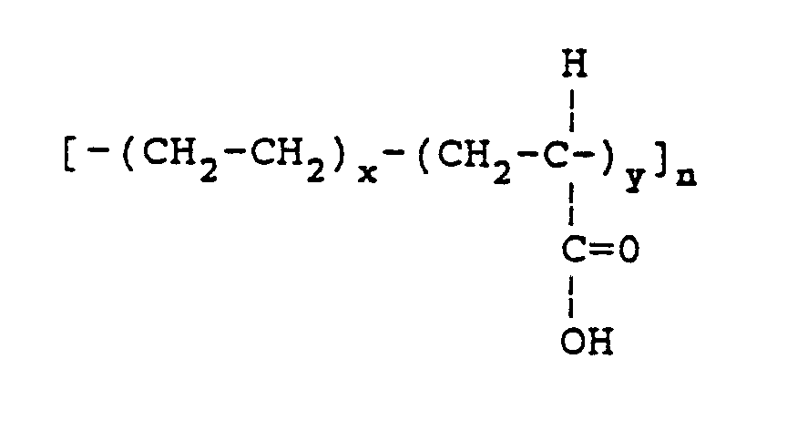
- Verfahren nach Anspruch 6, bei dem der Ethylen-Acrylsäure-Copolymer ein Molekulargewicht von ca. 500 bis ca. 10.000 g/mol aufweist.
- Verfahren nach einem der vorangehenden Ansprüche, bei dem der vernetzbare Konstituent ca. 1 bis ca. 30 Gew.-% der ersten reaktiven Tintenkomponente umfaßt.
- Verfahren nach einem der vorangehenden Ansprüche, bei dem das Vernetzungsmittel Diethylentriamin ist; 1,3-Pentandiamin; 1,6-Hexandiamin; Polyoxypropylendiamin; Polyethylenglykol (PEG); oder Glyzerin.
- Verfahren nach einem der Ansprüche 1 bis 8, bei dem das Vernetzungsmittel eine multifunktionelle Silanverbindung ist.
- Verfahren nach Anspruch 10, bei dem das Vernetzungsmittel Dimethyldiacetorysilan ist; Methyltriethoxysilan; Vinylmethyldiacetoxysilan; Methyltrimethoxysilan; Ethyltriacetoxysilan; Dimethyltetramethoxy-disiloxan; Methyltriacetoxysilan; Tetraethoxysilan; Vinyltriacetoxysilan; Tetramethoxysilan; Siliciumtetraazetat; Tetrapropoxysilan; Dimethyldiethoxysilan; 1,1,3,3-Tetramethyl-1,3-diethoxydisiloxan; Bis(N-methylbenzylamido)-ethoxymethylsilan; Bis(dimethylamino)-dimethylsilan; Bis(dimethylamino)-methylvinylsilan; Tris(dimethylamino)-methylsilan; Tris(cyclohexylamino)-methylsilan; Vinyltris(methylethylketoximin)-silan; Methyltris(methylethylketoxim)-Silan; Vinyltris(isopropenoxy)-silan; Tetramethyldisiloxan; 1,3,5,7-Tetramethylcyclotetrasiloxan; ein Methylhydrocyclosiloxane; 1,3-Divinyltetramethyl-disiloxan; 1,3,5-Trivinyl-1,1,3,5,5-pentamethyl-trisiloxan; oder Tetravinyltetramethylcyclo-tetrasiloxan.
- Verfahren nach einem der vorangehenden Ansprüche, bei dem der vernetzbare Konstituent eine Dimersäure ist.
- Verfahren nach Anspruch 12, bei dem der vernetzbare Konstituent eine Harz-Dimersäure ist.
- Verfahren nach Anspruch 12, bei dem das Vernetzungsmittel ein multifunktioneller Alkohol oder Polyamin ist.
- Verfahren nach einem der Ansprüche 1 bis 11 zur Verwendung in einem Tintenstrahldrucker für Phasenwechseltinte, der Tinte-auf-Abruf-Tintenstrahl-Drucktechniken verwendet und bei dem die reaktive Tinte ein aus mehreren Komponenten zusammengesetztes reaktives Tintensystem ist, das eine Basis-Tintenkomponente enthält, die einen Phasenwechseltinten-Träger und ein kompatibles Färbemittel umfaßt sowie einen vernetzbaren Konstituenten, der so ausgebildet ist, daß er einem Substrat in flüssiger Form zugegeben werden kann, und ein Härtemittel, das ein Vernetzungsmittel umfaßt, welches mit dem vernetzbaren Konstituenten in der Basis-Tintenkomponente reagiert und so ausgebildet ist, das es dem Substrat getrennt von der Basis-Tintenkomponente zugegeben werden kann und bei Kontakt mit dem vernetzbaren Konstituenten der Basis-Tintenkomponente eine vernetzte Tinte erzeugt.
- Verfahren nach Anspruch 15, bei dem das aus mehreren Komponenten bestehende reaktive Tintensystem zusätzlich eine Katalysator-Komponente enthält.
- Druckverfahren unter Verwendung einer reaktiven Tintenzusammensetzung, bei dem eine Basis-Tintenkomponente, die einen Phasenwechseltinten-Träger-Konstituenten und einen vernetzbaren Konstituenten enthält, getrennt von einem Vernetzungsmittel auf ein Substrat aufgetragen wird, wobei das Verfahren die folgenden Schritte umfaßt:Auftragen des Vernetzungsmittels auf die Oberfläche eines Aufnahmesubstrats zum Erhalt einer beschichteten Oberfläche; undnachfolgendem Auftragen der Basis-Tintenkomponente auf die beschichtete Oberfläche, wobei Tintenstrahldrucktechniken angewandt werden, und, indem man den vernetzbaren Konstituenten der Basis-Tintenkomponente dem Vernetzungsmittel des Härtemittels aussetzt, Erzeugen einer vernetzten Tintenschicht.
- Verfahren nach Anspruch 17, bei dem das Substrat eine intermediäre Trägeroberfläche ist, und die vernetzte Tintenschicht anschließend auf ein weiteres Aufnahmesubstrat übertragen wird.
- Verfahren nach Anspruch 17 oder 18, bei dem das Aufnahmesubstrat eine Fluid-Schicht als intermediäre Trägeroberfläche aufweist und das Vernetzungsmittel und die Basis-Tintenkomponente auf die intermediäre Trägeroberfläche aufgetragen werden.
- Verfahren nach Anspruch 19, das das Vermengen des Vernetzungsmittels mit dem Fluid der Fluid-Schicht zum Erhalt eines vernetzenden Auslöser-Fluids umfaßt.
- Verfahren nach einem der vorangehenden Ansprüche, bei dem der vernetzbare Konstituent vernetzt wird, indem man ihn einer Bestrahlung aussetzt.
- Verfahren nach Anspruch 21, bei dem die Bestrahlung von einer Kobalt-60-Quelle herrührt, von einem Hoch- oder Niedrigenergie-Elektronenbeschleuniger; sichtbares Licht, UV-Licht, Infrarot-Energie, Plasmaentladung oder Glimmentladung ist, oder von einem Laser stammt.
- Drucksubstrat für die Verwendung beim reaktiven Drucken, wobei ein reaktives Tintensystem verwendet wird, das eine erste reaktive Tintenkomponente umfaßt, die einen vernetzbaren Tintenträgerkonstituenten zusammen mit einem kompatiblen Färbemittel und einer getrennten zweiten reaktiven Tintenkomponente enthält, wobei das Drucksubstrat eine druckaufnehmende Oberfläche aufweist, die eine Ladung der zweiten reaktiven Tintenkomponente, die von dem Drucksubstrat getragen wird, einer Reaktion mit Ablagerungen der ersten reaktiven Tintenkomponente aussetzt, wenn diese auf die druckaufnehmende Oberfläche des Drucksubstrats bei der Druckverwendung gedruckt werden, wobei die Reaktion das Vernetzen des vernetzbaren Tintenträger-Konstituenten der ersten reaktiven Tintenkomponente durch Aussetzung des vernetzbaren Konstituenten der ersten reaktiven Tintenkomponente der zweiten reaktiven Tintenkomponente unter Vernetzungsbedingungen herbeiführt, wobei die zweite reaktive Tintenkomponente eine Substanz umfaßt, die als Mittel zum Teilnehmen bzw. Initiieren oder Unterstützen der Vernetzung wirkt, und wobei die Tintenkomponenten Bestandteile einer Phasenwechseltinte sind.
- Drucksubstrat nach Anspruch 23, bei dem der vernetzbare Konstituent gemäß einem der Ansprüche 5 bis 7 definiert ist.
- Drucksubstrat nach Anspruch 23 oder 27, bei dem das Vernetzungsmittel gemäß einem der Ansprüche 9 bis 11 definiert ist.
- Drucksubstrat nach Anspruch 23 oder 24, bei dem die reaktive Tinte ein gemäß Anspruch 15 definiertes System ist.
- Tintenstrahldrucker mit einem Tintenstrahldruckkopf sowie einer Einrichtung, die den Druckkopf und eine druckaufnehmende Oberfläche relativ zueinander verschiebt, so daß der Druckkopf sukzessive Druckadressen auf der Oberfläche in druckaufnehmender Beziehung dazu erhält, wobei ein Tintenstrahltinten-Behälter für eine erste reaktive Tintenkomponente eines reaktiven Phasenwechseltintensystems vorgesehen ist, eine Einrichtung zum Erhitzen dieser Komponente darin, so daß diese in flüssiggeschmolzener Form vorliegt, eine Einrichtung, die den Behälter zum Kopf bewegt, um die erste flüssige Komponente zum Kopf zu führen, ein weiterer Behälter zur Aufnahme einer zweiten reaktiven Tintenkomponente des Tintensystems und eine Einrichtung, die so aufgebaut und angeordnet ist, daß sie die zweite reaktive Tintenkomponente des anderen Behälter zum druckaufnehmenden Substrat über im wesentlichen die gesamte druckaufnehmende Oberfläche auftragen kann.
- Tintenstrahldrucker nach Anspruch 27, bei dem die druckaufnehmende Oberfläche eine Transferoberfläche ist, die für den Grenzflächen-Kontakt von Druckschichten der ersten reaktiven Tintenkomponente mit einem Drucksubstrat ausgebildet ist, das als permanenter bedruckter Träger von Druckinformationen vorgesehen ist.
- Verwendung eines Mittels, das an der Vernetzungsreaktion teilnimmt, sie initiiert oder fördert, wobei die Vernetzungsreaktion als eine Beschichtung auf eine tintenaufnehmende Oberfläche bezeichnet wird, die so ausgebildet ist, daß sie bei ihren Druckadressen Ablagerungen einer Zusammensetzung aufnimmt, die einen Phasenwechseltinten-Träger-Konstituenten und ein kompatibles Färbemittel enthält, wobei der Tintenträger-Konstituent ein Material enthält, das durch eine Vernetzungsreaktion gehärtet werden kann, an der das Mittel teilnimmt oder Initiator bzw Förderer ist.
- Reaktive Phasenwechseltinte zur Verwendung für Tintenstrahldrucker, die folgendes umfaßt:(i) eine Basis-Tintenkomponente, die einen Phasenwechseltinten-Träger-Konstituenten aufweist sowie ein kompatibles Färbemittel und einen vernetzbaren Konstituenten, der so ausgebildet ist, daß er auf ein Substrat in flüssiger Form aufgetragen werden kann; und(ii) ein Vernetzungsmittel, das mit dem vernetzbaren Konstituenten in der Basis-Tintenkomponente reagieren kann und so ausgebildet ist, das es auf ein Aufnahmesubstrat getrennt von der Basis-Tintenkomponente aufgetragen werden kann, und, durch Kontakt mit dem vernetzbaren Konstituenten der Basis-Tintenkomponente, eine vernetzte Tinte erzeugen kann.
- Reaktives Tintensystem zur Verwendung in Phasenwechseltinte-Tintenstrahldruckern, die Tinte-auf-Abruf-Tintenstrahl-Drucktechniken verwenden, welches folgendes umfaßt:eine Basis-Tintenkomponente, die einen Phasenwechseltinten-Träger enthält, ein kompatibles Färbemittel und einen vernetzbaren Konstituenten, der so ausgebildet ist, daß er auf ein Substrat in flüssiger Form aufgetragen werden kann, und ein Härtemittel, das ein Vernetzungsmittel enthält, das mit dem vernetzbaren Konstituenten in der Basis-Tintenkomponente reagieren kann und so ausgebildet ist, daß es auf das Substrat getrennt von der Basis-Tintenkomponente aufgebracht werden kann, um durch Kontakt mit dem vernetzbaren Konstituenten der Basistintenkomponente, eine vernetzte Tinte zu erzeugen.
- Reaktive Tinte nach Anspruch 30 oder 31, die als Einheitspackung aufgebaut ist, die eine eingeschlossene Menge der Basis-Tintenkomponente als eine Komponente und eine getrennt davon eingeschlossene Menge eines Härtemittels für den vernetzbaren Konstituenten der Basis-Tintenkomponente enthält, wobei die beiden Mengen für die Reaktion, an der beide bei Verwendung teilnehmen, passend gewählt sind oder ein Überschuß an Härtemittel vorliegt.
- Reaktive Phasenwechseltinte für einen Tintenstrahldrucker, die die folgenden Konstituenten als getrennte Komponenten umfaßt, die so ausgelegt sind, daß sie bei Verwendung kombiniert werden:(i) eine erste Komponente, die einen Phasenwechseltinten-Träger, ein kompatibles Färbemittel und einen vernetzbaren Konstituenten gemäß einem der Ansprüche 6, 7, 12 oder 13 umfaßt; und(ii) ein Vernetzungsmittel, das mit dem vernetzbaren Konstituenten reagieren kann.
- Tinte nach Anspruch 33, bei der der Tintenträger wässerig und der vernetzbare Konstituent Polyvinylalkohol ist; Polyacrylsäure; Polyacrylamid; Polyethylenimin; Polyvinylpyrrolidon oder Polyvinylpyrrolidon-co-Acrylsäure ist.
- Tinte nach Anspruch 34, bei der das Vernetzungsmittel ein Metallion aus Gruppe I oder II enthält.
- Tinte nach Anspruch 35, bei der das Vernetzungsmittel Natriumtetraboratdecahydrat oder Natriumhydroxid enthält.
Applications Claiming Priority (6)
| Application Number | Priority Date | Filing Date | Title |
|---|---|---|---|
| US98164692A | 1992-11-25 | 1992-11-25 | |
| US981677 | 1992-11-25 | ||
| US981646 | 1992-11-25 | ||
| US07/981,677 US5372852A (en) | 1992-11-25 | 1992-11-25 | Indirect printing process for applying selective phase change ink compositions to substrates |
| US08/005,970 US5380769A (en) | 1993-01-19 | 1993-01-19 | Reactive ink compositions and systems |
| US5970 | 1993-01-19 |
Publications (3)
| Publication Number | Publication Date |
|---|---|
| EP0604024A2 EP0604024A2 (de) | 1994-06-29 |
| EP0604024A3 EP0604024A3 (de) | 1995-05-24 |
| EP0604024B1 true EP0604024B1 (de) | 1999-01-27 |
Family
ID=27358004
Family Applications (3)
| Application Number | Title | Priority Date | Filing Date |
|---|---|---|---|
| EP93309426A Expired - Lifetime EP0604025B1 (de) | 1992-11-25 | 1993-11-25 | Bildherstellungsverfahren |
| EP93309424A Expired - Lifetime EP0604023B1 (de) | 1992-11-25 | 1993-11-25 | Verfahren zum Aufbringen von selektiver Phaseaustauschtinte zum Substraten durch indirekten Druck |
| EP93309425A Expired - Lifetime EP0604024B1 (de) | 1992-11-25 | 1993-11-25 | Reaktive Tintenzusammensetzungen und System |
Family Applications Before (2)
| Application Number | Title | Priority Date | Filing Date |
|---|---|---|---|
| EP93309426A Expired - Lifetime EP0604025B1 (de) | 1992-11-25 | 1993-11-25 | Bildherstellungsverfahren |
| EP93309424A Expired - Lifetime EP0604023B1 (de) | 1992-11-25 | 1993-11-25 | Verfahren zum Aufbringen von selektiver Phaseaustauschtinte zum Substraten durch indirekten Druck |
Country Status (2)
| Country | Link |
|---|---|
| EP (3) | EP0604025B1 (de) |
| DE (3) | DE69313090T2 (de) |
Cited By (1)
| Publication number | Priority date | Publication date | Assignee | Title |
|---|---|---|---|---|
| WO2022208112A1 (en) | 2021-04-01 | 2022-10-06 | Sun Chemical Corporation | Water-based polymeric colorant inks |
Families Citing this family (17)
| Publication number | Priority date | Publication date | Assignee | Title |
|---|---|---|---|---|
| US5805191A (en) * | 1992-11-25 | 1998-09-08 | Tektronix, Inc. | Intermediate transfer surface application system |
| US5502476A (en) * | 1992-11-25 | 1996-03-26 | Tektronix, Inc. | Method and apparatus for controlling phase-change ink temperature during a transfer printing process |
| US6887640B2 (en) | 2002-02-28 | 2005-05-03 | Sukun Zhang | Energy activated electrographic printing process |
| US7041424B2 (en) | 1994-11-07 | 2006-05-09 | Ming Xu | Energy activated electrographic printing process |
| US6348939B1 (en) | 1999-05-28 | 2002-02-19 | Sawgrass Systems, Inc. | Digital printable reactive dye and process |
| WO1996032811A2 (en) * | 1995-04-12 | 1996-10-17 | Eastman Kodak Company | High capacity compressed document image storage for digital color printers |
| IL116123A (en) | 1995-11-23 | 1999-07-14 | Scitex Corp Ltd | System and method for printing |
| US5754209A (en) * | 1996-11-01 | 1998-05-19 | Sterling Diagnostic Imaging, Inc. | Printing method for producing gradient images |
| US5821956A (en) * | 1996-11-27 | 1998-10-13 | Tektronix, Inc. | Method to improve solid ink output resolution |
| US6354700B1 (en) | 1997-02-21 | 2002-03-12 | Ncr Corporation | Two-stage printing process and apparatus for radiant energy cured ink |
| US6140391A (en) * | 1998-10-09 | 2000-10-31 | Marconi Data Systems Inc. | Reactive jet ink composition |
| PT1089879E (pt) * | 1999-04-23 | 2006-11-30 | Sawgrass Systems Inc | Processo de impressão a jacto de tinta utilizando tintas reactivas |
| US6849370B2 (en) | 2001-10-16 | 2005-02-01 | Barbara Wagner | Energy activated electrographic printing process |
| CN102164971B (zh) * | 2008-08-25 | 2014-05-28 | 陶氏环球技术有限责任公司 | 使用低聚胺交联含羧基的聚合物的方法 |
| US8096649B2 (en) * | 2009-11-24 | 2012-01-17 | Xerox Corporation | Image conditioning coating |
| US8690309B2 (en) * | 2011-04-27 | 2014-04-08 | Xerox Corporation | Print process for phase separation ink |
| CN109916903A (zh) * | 2019-04-08 | 2019-06-21 | 浙江大学 | 可延展柔性集成器件转印技术测试表征和转印自动化平台 |
Family Cites Families (32)
| Publication number | Priority date | Publication date | Assignee | Title |
|---|---|---|---|---|
| BE755392A (fr) | 1969-08-28 | 1971-02-01 | Teletype Corp | Encre et appareil d'impression electrostatique |
| US4390369A (en) | 1981-12-17 | 1983-06-28 | Exxon Research And Engineering Co. | Natural wax-containing ink jet inks |
| US4421816A (en) | 1981-11-18 | 1983-12-20 | Advanced Graphic Technology | Dry transfer decal and method of manufacture |
| US4659383A (en) | 1981-12-17 | 1987-04-21 | Exxon Printing Systems, Inc. | High molecular weight, hot melt impulse ink jet ink |
| US4484948A (en) | 1981-12-17 | 1984-11-27 | Exxon Research And Engineering Co. | Natural wax-containing ink jet inks |
| US4454179A (en) | 1982-05-10 | 1984-06-12 | Minnesota Mining And Manufacturing Company | Dry transfer article |
| US4503111A (en) | 1983-05-09 | 1985-03-05 | Tektronix, Inc. | Hydrophobic substrate with coating receptive to inks |
| US4538156A (en) | 1983-05-23 | 1985-08-27 | At&T Teletype Corporation | Ink jet printer |
| US4731647A (en) | 1983-06-03 | 1988-03-15 | Matsushita Electric Industrial Co., Ltd. | Method and apparatus for printing ink by dissolving colorant with deposited solvent |
| DE3579067D1 (de) | 1984-05-10 | 1990-09-13 | Willett Int Ltd | Verfahren zur beschichtung eines substrates mit thermoplastischen ttinten, und beschichtungszusammensetzung. |
| US4555437A (en) | 1984-07-16 | 1985-11-26 | Xidex Corporation | Transparent ink jet recording medium |
| US4547405A (en) | 1984-12-13 | 1985-10-15 | Polaroid Corporation | Ink jet transparency |
| DE3583130D1 (de) | 1984-12-31 | 1991-07-11 | Howtek Inc | Verfahren zum farbdrucken mit tintenstrahl. |
| EP0206286B1 (de) | 1985-06-25 | 1990-05-23 | Howtek, Inc. | Tinte für den Tintenstrahldruck |
| US4743920A (en) | 1985-07-31 | 1988-05-10 | Canon Kabushiki Kaisha | Thermal transfer recording method and apparatus |
| US4673303A (en) | 1985-10-07 | 1987-06-16 | Pitney Bowes Inc. | Offset ink jet postage printing |
| US4649064A (en) * | 1986-03-10 | 1987-03-10 | Eastman Kodak Company | Rapid-drying recording element for liquid ink marking |
| US4801473A (en) | 1987-05-14 | 1989-01-31 | Spectra, Inc. | Method for preparing a hot melt ink transparency |
| JP2767796B2 (ja) * | 1987-12-03 | 1998-06-18 | セイコーエプソン株式会社 | インクジエットプリンタ |
| EP0320594B2 (de) | 1987-12-14 | 1998-04-15 | Nippon Shokubai Co., Ltd. | Wässrige härtbare Harzdispersionen, Verfahren zu deren Herstellung und deren Verwendung |
| US4899761A (en) | 1988-03-31 | 1990-02-13 | Brown Mark D | Apparatus and method for measuring spinal instability |
| US4889560A (en) | 1988-08-03 | 1989-12-26 | Tektronix, Inc. | Phase change ink composition and phase change ink produced therefrom |
| JP2699450B2 (ja) * | 1988-09-22 | 1998-01-19 | 富士ゼロックス株式会社 | インクジェット記録装置 |
| US5017644A (en) | 1989-05-22 | 1991-05-21 | Xerox Corporation | Ink jet ink compositions |
| US5087930A (en) | 1989-11-01 | 1992-02-11 | Tektronix, Inc. | Drop-on-demand ink jet print head |
| US4992304A (en) * | 1989-12-27 | 1991-02-12 | Tektronix, Inc. | Methods for coating a light-transmissive substrate to promote adhesion of a phase-change ink |
| US5108505A (en) | 1990-05-16 | 1992-04-28 | Hewlett-Packard Company | Waterfast inks via cyclodextrin inclusion complex |
| US5099256A (en) | 1990-11-23 | 1992-03-24 | Xerox Corporation | Ink jet printer with intermediate drum |
| US5129948A (en) | 1991-05-16 | 1992-07-14 | Xerox Corporation | Ink for ink jet printing |
| JP3174602B2 (ja) * | 1991-10-02 | 2001-06-11 | 株式会社リコー | インクジェット記録装置 |
| WO1994001283A1 (en) * | 1992-07-02 | 1994-01-20 | Seiko Epson Corporation | Intermediate transfer type ink jet recording method |
| EP0583168B1 (de) * | 1992-08-12 | 1998-10-28 | Seiko Epson Corporation | Verfahren und Vorrichtung für Tintenstrahlaufzeichnung |
-
1993
- 1993-11-25 EP EP93309426A patent/EP0604025B1/de not_active Expired - Lifetime
- 1993-11-25 DE DE69313090T patent/DE69313090T2/de not_active Expired - Fee Related
- 1993-11-25 DE DE69323287T patent/DE69323287T2/de not_active Expired - Fee Related
- 1993-11-25 DE DE69323288T patent/DE69323288T2/de not_active Expired - Fee Related
- 1993-11-25 EP EP93309424A patent/EP0604023B1/de not_active Expired - Lifetime
- 1993-11-25 EP EP93309425A patent/EP0604024B1/de not_active Expired - Lifetime
Cited By (1)
| Publication number | Priority date | Publication date | Assignee | Title |
|---|---|---|---|---|
| WO2022208112A1 (en) | 2021-04-01 | 2022-10-06 | Sun Chemical Corporation | Water-based polymeric colorant inks |
Also Published As
| Publication number | Publication date |
|---|---|
| DE69323288D1 (de) | 1999-03-11 |
| EP0604024A2 (de) | 1994-06-29 |
| EP0604023A3 (de) | 1995-05-17 |
| EP0604024A3 (de) | 1995-05-24 |
| EP0604025B1 (de) | 1999-01-27 |
| EP0604023A2 (de) | 1994-06-29 |
| DE69323288T2 (de) | 1999-06-02 |
| DE69313090T2 (de) | 1998-03-19 |
| EP0604023B1 (de) | 1997-08-13 |
| DE69323287D1 (de) | 1999-03-11 |
| EP0604025A3 (de) | 1995-05-17 |
| EP0604025A2 (de) | 1994-06-29 |
| DE69323287T2 (de) | 1999-06-02 |
| DE69313090D1 (de) | 1997-09-18 |
Similar Documents
| Publication | Publication Date | Title |
|---|---|---|
| US5380769A (en) | Reactive ink compositions and systems | |
| EP0604024B1 (de) | Reaktive Tintenzusammensetzungen und System | |
| US8220917B2 (en) | Image forming apparatus with a plurality of applying units | |
| JP4006374B2 (ja) | 画像形成方法、画像形成装置および記録物の製造方法 | |
| US6709096B1 (en) | Method of printing and layered intermediate used in inkjet printing | |
| US5541633A (en) | Ink jet printing of concealed images on carbonless paper | |
| EP1330357B1 (de) | Beschichtungslösung für zwischentransfermedium und tintenstrahldruckverfahren unter verwendung der beschichtungslösung | |
| US7371274B2 (en) | Water-based ink, ink jet recording method, ink cartridge, recording unit, ink jet recording apparatus, and image forming method. | |
| US8894198B2 (en) | Compositions compatible with jet printing and methods therefor | |
| JP4224239B2 (ja) | 湿潤性可融トナーによるインクジェット印刷画像 | |
| JPH0796603A (ja) | インクジェット記録装置 | |
| US4920361A (en) | Image recording method and apparatus therefor | |
| JPH06200204A (ja) | 熱溶融性インク及びそれを用いたインクジェット記録装置 | |
| JP6470663B2 (ja) | 画像マーキング装置、受像媒体基材上への画像形成方法、及び画像形成システム | |
| KR20180026554A (ko) | 프린트방법 및 액체 잉크젯 잉크 | |
| JP3955459B2 (ja) | カラー画像上への透明保護オーバーコート用ベース材料 | |
| EP1325285B1 (de) | Verfahren zum inkjet-drucken mit einem farbstoff mit hohem anfeuchtungsmittelgehalt | |
| EP0191498B1 (de) | Wärmeübertragungsblatt | |
| JP3559637B2 (ja) | 画像形成方法、インクセット、インク、インクの調製方法及びカラー画像の異色境界滲みの低減方法 | |
| EP0919370B1 (de) | Verfahren zur Herstellung einer positiv arbeitenden Druckplatte, von einem lithographischen Träger mit einem vernetzten hydrophilen Substrat ausgehend | |
| JP3115018B2 (ja) | 記録装置 | |
| JP2000301050A (ja) | インクジェットによる非接触コーティング方法 |
Legal Events
| Date | Code | Title | Description |
|---|---|---|---|
| PUAI | Public reference made under article 153(3) epc to a published international application that has entered the european phase |
Free format text: ORIGINAL CODE: 0009012 |
|
| AK | Designated contracting states |
Kind code of ref document: A2 Designated state(s): CH DE FR GB IT LI |
|
| 17P | Request for examination filed |
Effective date: 19941102 |
|
| PUAL | Search report despatched |
Free format text: ORIGINAL CODE: 0009013 |
|
| AK | Designated contracting states |
Kind code of ref document: A3 Designated state(s): CH DE FR GB IT LI |
|
| 17Q | First examination report despatched |
Effective date: 19960416 |
|
| GRAG | Despatch of communication of intention to grant |
Free format text: ORIGINAL CODE: EPIDOS AGRA |
|
| GRAG | Despatch of communication of intention to grant |
Free format text: ORIGINAL CODE: EPIDOS AGRA |
|
| GRAH | Despatch of communication of intention to grant a patent |
Free format text: ORIGINAL CODE: EPIDOS IGRA |
|
| GRAH | Despatch of communication of intention to grant a patent |
Free format text: ORIGINAL CODE: EPIDOS IGRA |
|
| GRAA | (expected) grant |
Free format text: ORIGINAL CODE: 0009210 |
|
| AK | Designated contracting states |
Kind code of ref document: B1 Designated state(s): CH DE FR GB IT LI |
|
| PG25 | Lapsed in a contracting state [announced via postgrant information from national office to epo] |
Ref country code: IT Free format text: LAPSE BECAUSE OF FAILURE TO SUBMIT A TRANSLATION OF THE DESCRIPTION OR TO PAY THE FEE WITHIN THE PRE;WARNING: LAPSES OF ITALIAN PATENTS WITH EFFECTIVE DATE BEFORE 2007 MAY HAVE OCCURRED AT ANY TIME BEFORE 2007. THE CORRECT EFFECTIVE DATE MAY BE DIFFERENT FROM THE ONE RECORDED.SCRIBED TIME-LIMIT Effective date: 19990127 |
|
| REG | Reference to a national code |
Ref country code: CH Ref legal event code: EP |
|
| REG | Reference to a national code |
Ref country code: CH Ref legal event code: NV Representative=s name: E. BLUM & CO. PATENTANWAELTE |
|
| REF | Corresponds to: |
Ref document number: 69323287 Country of ref document: DE Date of ref document: 19990311 |
|
| ET | Fr: translation filed | ||
| PLBE | No opposition filed within time limit |
Free format text: ORIGINAL CODE: 0009261 |
|
| STAA | Information on the status of an ep patent application or granted ep patent |
Free format text: STATUS: NO OPPOSITION FILED WITHIN TIME LIMIT |
|
| 26N | No opposition filed | ||
| REG | Reference to a national code |
Ref country code: CH Ref legal event code: PUE Owner name: TEKTRONIX, INC. TRANSFER- XEROX CORPORATION Ref country code: CH Ref legal event code: NV Representative=s name: KATZAROV S.A. |
|
| REG | Reference to a national code |
Ref country code: GB Ref legal event code: 732E |
|
| REG | Reference to a national code |
Ref country code: FR Ref legal event code: TP |
|
| REG | Reference to a national code |
Ref country code: CH Ref legal event code: NV Representative=s name: E. BLUM & CO. PATENTANWAELTE |
|
| REG | Reference to a national code |
Ref country code: GB Ref legal event code: IF02 |
|
| REG | Reference to a national code |
Ref country code: CH Ref legal event code: PFA Owner name: XEROX CORPORATION Free format text: XEROX CORPORATION#800 LONG RIDGE ROAD#STAMFORD (CT 06904) (US) -TRANSFER TO- XEROX CORPORATION#800 LONG RIDGE ROAD#STAMFORD (CT 06904) (US) |
|
| PGFP | Annual fee paid to national office [announced via postgrant information from national office to epo] |
Ref country code: DE Payment date: 20081120 Year of fee payment: 16 Ref country code: CH Payment date: 20081130 Year of fee payment: 16 |
|
| PGFP | Annual fee paid to national office [announced via postgrant information from national office to epo] |
Ref country code: FR Payment date: 20081112 Year of fee payment: 16 |
|
| PGFP | Annual fee paid to national office [announced via postgrant information from national office to epo] |
Ref country code: GB Payment date: 20081119 Year of fee payment: 16 |
|
| REG | Reference to a national code |
Ref country code: CH Ref legal event code: PL |
|
| GBPC | Gb: european patent ceased through non-payment of renewal fee |
Effective date: 20091125 |
|
| REG | Reference to a national code |
Ref country code: FR Ref legal event code: ST Effective date: 20100730 |
|
| PG25 | Lapsed in a contracting state [announced via postgrant information from national office to epo] |
Ref country code: LI Free format text: LAPSE BECAUSE OF NON-PAYMENT OF DUE FEES Effective date: 20091130 Ref country code: FR Free format text: LAPSE BECAUSE OF NON-PAYMENT OF DUE FEES Effective date: 20091130 Ref country code: CH Free format text: LAPSE BECAUSE OF NON-PAYMENT OF DUE FEES Effective date: 20091130 |
|
| PG25 | Lapsed in a contracting state [announced via postgrant information from national office to epo] |
Ref country code: DE Free format text: LAPSE BECAUSE OF NON-PAYMENT OF DUE FEES Effective date: 20100601 |
|
| PG25 | Lapsed in a contracting state [announced via postgrant information from national office to epo] |
Ref country code: GB Free format text: LAPSE BECAUSE OF NON-PAYMENT OF DUE FEES Effective date: 20091125 |