EP0604023B1 - Verfahren zum Aufbringen von selektiver Phaseaustauschtinte zum Substraten durch indirekten Druck - Google Patents
Verfahren zum Aufbringen von selektiver Phaseaustauschtinte zum Substraten durch indirekten Druck Download PDFInfo
- Publication number
- EP0604023B1 EP0604023B1 EP93309424A EP93309424A EP0604023B1 EP 0604023 B1 EP0604023 B1 EP 0604023B1 EP 93309424 A EP93309424 A EP 93309424A EP 93309424 A EP93309424 A EP 93309424A EP 0604023 B1 EP0604023 B1 EP 0604023B1
- Authority
- EP
- European Patent Office
- Prior art keywords
- phase change
- change ink
- ink composition
- composition
- psi
- Prior art date
- Legal status (The legal status is an assumption and is not a legal conclusion. Google has not performed a legal analysis and makes no representation as to the accuracy of the status listed.)
- Expired - Lifetime
Links
Images


Classifications
-
- B—PERFORMING OPERATIONS; TRANSPORTING
- B41—PRINTING; LINING MACHINES; TYPEWRITERS; STAMPS
- B41M—PRINTING, DUPLICATING, MARKING, OR COPYING PROCESSES; COLOUR PRINTING
- B41M5/00—Duplicating or marking methods; Sheet materials for use therein
- B41M5/26—Thermography ; Marking by high energetic means, e.g. laser otherwise than by burning, and characterised by the material used
- B41M5/382—Contact thermal transfer or sublimation processes
- B41M5/38257—Contact thermal transfer or sublimation processes characterised by the use of an intermediate receptor
-
- B—PERFORMING OPERATIONS; TRANSPORTING
- B41—PRINTING; LINING MACHINES; TYPEWRITERS; STAMPS
- B41J—TYPEWRITERS; SELECTIVE PRINTING MECHANISMS, i.e. MECHANISMS PRINTING OTHERWISE THAN FROM A FORME; CORRECTION OF TYPOGRAPHICAL ERRORS
- B41J11/00—Devices or arrangements of selective printing mechanisms, e.g. ink-jet printers or thermal printers, for supporting or handling copy material in sheet or web form
- B41J11/0015—Devices or arrangements of selective printing mechanisms, e.g. ink-jet printers or thermal printers, for supporting or handling copy material in sheet or web form for treating before, during or after printing or for uniform coating or laminating the copy material before or after printing
- B41J11/002—Curing or drying the ink on the copy materials, e.g. by heating or irradiating
- B41J11/0024—Curing or drying the ink on the copy materials, e.g. by heating or irradiating using conduction means, e.g. by using a heated platen
- B41J11/00244—Means for heating the copy materials before or during printing
-
- B—PERFORMING OPERATIONS; TRANSPORTING
- B41—PRINTING; LINING MACHINES; TYPEWRITERS; STAMPS
- B41J—TYPEWRITERS; SELECTIVE PRINTING MECHANISMS, i.e. MECHANISMS PRINTING OTHERWISE THAN FROM A FORME; CORRECTION OF TYPOGRAPHICAL ERRORS
- B41J2/00—Typewriters or selective printing mechanisms characterised by the printing or marking process for which they are designed
- B41J2/005—Typewriters or selective printing mechanisms characterised by the printing or marking process for which they are designed characterised by bringing liquid or particles selectively into contact with a printing material
- B41J2/0057—Typewriters or selective printing mechanisms characterised by the printing or marking process for which they are designed characterised by bringing liquid or particles selectively into contact with a printing material where an intermediate transfer member receives the ink before transferring it on the printing material
-
- B—PERFORMING OPERATIONS; TRANSPORTING
- B41—PRINTING; LINING MACHINES; TYPEWRITERS; STAMPS
- B41J—TYPEWRITERS; SELECTIVE PRINTING MECHANISMS, i.e. MECHANISMS PRINTING OTHERWISE THAN FROM A FORME; CORRECTION OF TYPOGRAPHICAL ERRORS
- B41J2/00—Typewriters or selective printing mechanisms characterised by the printing or marking process for which they are designed
- B41J2/005—Typewriters or selective printing mechanisms characterised by the printing or marking process for which they are designed characterised by bringing liquid or particles selectively into contact with a printing material
- B41J2/01—Ink jet
-
- B—PERFORMING OPERATIONS; TRANSPORTING
- B41—PRINTING; LINING MACHINES; TYPEWRITERS; STAMPS
- B41M—PRINTING, DUPLICATING, MARKING, OR COPYING PROCESSES; COLOUR PRINTING
- B41M3/00—Printing processes to produce particular kinds of printed work, e.g. patterns
-
- B—PERFORMING OPERATIONS; TRANSPORTING
- B41—PRINTING; LINING MACHINES; TYPEWRITERS; STAMPS
- B41M—PRINTING, DUPLICATING, MARKING, OR COPYING PROCESSES; COLOUR PRINTING
- B41M3/00—Printing processes to produce particular kinds of printed work, e.g. patterns
- B41M3/001—Printing processes to produce particular kinds of printed work, e.g. patterns using chemical colour-formers or chemical reactions, e.g. leuco dyes or acids
-
- B—PERFORMING OPERATIONS; TRANSPORTING
- B41—PRINTING; LINING MACHINES; TYPEWRITERS; STAMPS
- B41M—PRINTING, DUPLICATING, MARKING, OR COPYING PROCESSES; COLOUR PRINTING
- B41M7/00—After-treatment of prints, e.g. heating, irradiating, setting of the ink, protection of the printed stock
- B41M7/009—After-treatment of prints, e.g. heating, irradiating, setting of the ink, protection of the printed stock using thermal means, e.g. infrared radiation, heat
-
- C—CHEMISTRY; METALLURGY
- C09—DYES; PAINTS; POLISHES; NATURAL RESINS; ADHESIVES; COMPOSITIONS NOT OTHERWISE PROVIDED FOR; APPLICATIONS OF MATERIALS NOT OTHERWISE PROVIDED FOR
- C09D—COATING COMPOSITIONS, e.g. PAINTS, VARNISHES OR LACQUERS; FILLING PASTES; CHEMICAL PAINT OR INK REMOVERS; INKS; CORRECTING FLUIDS; WOODSTAINS; PASTES OR SOLIDS FOR COLOURING OR PRINTING; USE OF MATERIALS THEREFOR
- C09D11/00—Inks
- C09D11/02—Printing inks
-
- C—CHEMISTRY; METALLURGY
- C09—DYES; PAINTS; POLISHES; NATURAL RESINS; ADHESIVES; COMPOSITIONS NOT OTHERWISE PROVIDED FOR; APPLICATIONS OF MATERIALS NOT OTHERWISE PROVIDED FOR
- C09D—COATING COMPOSITIONS, e.g. PAINTS, VARNISHES OR LACQUERS; FILLING PASTES; CHEMICAL PAINT OR INK REMOVERS; INKS; CORRECTING FLUIDS; WOODSTAINS; PASTES OR SOLIDS FOR COLOURING OR PRINTING; USE OF MATERIALS THEREFOR
- C09D11/00—Inks
- C09D11/30—Inkjet printing inks
- C09D11/34—Hot-melt inks
-
- B—PERFORMING OPERATIONS; TRANSPORTING
- B41—PRINTING; LINING MACHINES; TYPEWRITERS; STAMPS
- B41J—TYPEWRITERS; SELECTIVE PRINTING MECHANISMS, i.e. MECHANISMS PRINTING OTHERWISE THAN FROM A FORME; CORRECTION OF TYPOGRAPHICAL ERRORS
- B41J2/00—Typewriters or selective printing mechanisms characterised by the printing or marking process for which they are designed
- B41J2/005—Typewriters or selective printing mechanisms characterised by the printing or marking process for which they are designed characterised by bringing liquid or particles selectively into contact with a printing material
- B41J2/01—Ink jet
- B41J2/17—Ink jet characterised by ink handling
- B41J2/175—Ink supply systems ; Circuit parts therefor
- B41J2/17593—Supplying ink in a solid state
Definitions
- the present invention generally relates to selective phase change ink compositions and to a process for applying same to substrates, and more particularly to the application and use of such inks in a process in which phase change compositions having selective process capabilities are applied to a substrate in indirect printing processes where intermediate transfer surfaces are employed.
- phase change inks are in the solid phase at ambient temperature, but exist in the liquid phase at the elevated operating temperature of an ink jet printing device. At the jet operating temperature, droplets of liquid ink are ejected from the printing device and, when the ink droplets contact the surface of the printing media, they quickly solidify to form a predetermined pattern of solidified ink drops.
- the phase change ink comprises a phase change ink carrier composition which is combined with a phase change ink compatible colorant.
- a colored phase change ink will be formed by combining the above-described ink carrier composition with compatible subtractive primary colorants.
- the subtractive primary colored phase change inks of this invention comprise four component dyes, namely, cyan, magenta, yellow and black.
- the subtractive primary colorants employed typically comprise dyes from either class of Color Index (C.I.) Solvent Dyes, Disperse Dyes, modified Acid and Direct Dyes, and a limited number of Basic Dyes.
- Phase change ink is desirable since it remains in a solid phase at room temperature, during shipping, long-term storage, etc. Also, the problems associated with nozzle clogging due to ink evaporation are largely eliminated, thereby improving the reliability of ink jet printing. Furthermore, in prior art phase change ink jet printers where the ink droplets are applied directly onto the printing medium the droplets solidify immediately upon contact with the substrate, migration of ink along the printing medium is prevented and dot quality is improved. This is also true of the processes and ink compositions described herein.
- low melting point phase change inks when employed in printing onto a substrate, they exhibit offset problems, namely, when the printed substrates formed from these inks are stacked and stored for subsequent use, they can become adhered to one another, particularly if high ambient temperatures are experienced.
- U.S. Pat. No. 4,390,369 and U.S. Pat. No. 4,484,948 describe methods for producing monochrome phase change inks which employ a natural wax ink base, such as Japan wax, candelilla wax, carnauba wax, etc., which is printed by direct application from a drop-on-demand ink jet device at a temperature ranging between 65° C and 75° C.
- a monochrome ink composition is provided having an ink base comprising a C20-24 acid or alcohol, a ketone, and an acrylic resin plasticizer. These monochrome ink compositions are not durable and when printed by direct application can be smudged with routine handling and folding.
- amides which are solid at room temperature such as acetamide, are employed as printing inks.
- U.S. 4,684,956 is directed to monochrome phase change inks utilizing synthetic microcrystalline wax (hydrocarbon wax) and microcrystalline polyethylene wax. This molten composition can be applied to a variety of porous and non-porous substrates using a drop-on-demand ink jet direct application technique.
- EP 0177352 and EP 0206286 reference direct phase change ink jet printing in color.
- the ink bases for these systems comprise fatty acids, a thermoplastic polyethylene and a phase change material in the first application; and the alcohol portion of a thermal setting resin pair, a mixture of organic solvents (o- and p-toluene sulfonamide) and a dye in the second application.
- a hot-melt or phase change color ink composition having the properties of stability and uniformity of performance under ink jet printing conditions.
- the resinous binder for the above-described phase change ink is the condensation reaction product of one equivalent of polymerized fatty acid, two equivalents of diamine and two equivalents of a monocarboxylic acid.
- a hot melt ink for direct application by ink jet printing is provided.
- the colored ink jet images have a relatively narrow melting range and inhibit crystallinity upon quenching to reduce attenuation of transmitted light.
- Phase change ink compositions for direct application onto an underlying substrate are described in U.S. 4,889,560, U.S. 4,889,761, U.S. 4,992,304, U.S. 5,084,099, all of which are assigned to the assignee of this patent application, and all of which are incorporated herein by reference in pertinent part.
- the carrier composition of phase change inks preferably includes a fatty amide-containing compound. It may also include plasticizers and tackifiers. Thin films of substantially uniform thickness of this ink composition are rectilinearly light transmissive, so that the inks are suitable for preparing overhead transparencies when used in the manner described in the patents just referenced above.
- phase change ink processes in which the ink is jetted in the form of discrete drops directly onto a substrate.
- phase change ink systems such as U.S. 4,889,560
- special selective process capabilities are not required because the phase change ink is applied directly to the substrate by the use of an ink jet printing process.
- phase change inks which work in direct processes do not necessarily perform satisfactorily in indirect processes where the inks are first applied to an intermediate transfer surface and then to the final receiving substrate or surface.
- phase change ink of the present invention is indirectly applied to the substrate via an intermediate transfer surface.
- it is first deposited onto an intermediate transfer surface in a linewise fashion, as will be described hereinafter.
- the pattern of phase change ink on the intermediate transfer surface is then contact transferred to the substrate.
- the indirect application via an intermediate transfer surface of phase change inks by the process of the present invention requires certain mechanical and physical properties which are necessary to produce a printed substrate by applying a phase change ink composition first to an intermediate surface and then to a final receiving surface or substrate.
- the invention includes combining a phase change compatible colorant with a modified phase change ink carrier composition to unexpectedly produce an ink with specific desired fluidic and mechanical properties which meets the parameters needed for indirect application. It also includes providing a process for the indirect application via an intermediate transfer surface of said phase change ink composition to a final receiving surface or substrate to which the phase change ink composition is fixed to produce a finished printed substrate.
- the phase change ink composition of the present invention is formulated by combining a modified phase change ink carrier composition having selective process capabilities with a phase change compatible colorant composition.
- the selective phase change ink composition produced thereby, after it is formulated, is typically cast into solid ink sticks and placed into an ink jet printing device. Then, the temperature is raised to a first elevated operating temperature where a liquid phase with selective fluidic properties is formed. The ink is then typically held as a liquid at this relatively high operating temperature in the reservoir and print head of an ink jet printer.
- the liquid phase ink composition can then be indirectly applied in a predetermined pattern to a substrate.
- the ink composition can then be deposited onto an intermediate transfer surface (see European Patent Application N o 93 309426.0; 604025).
- the ink composition is maintained as a solid, in a predetermined pattern on the intermediate transfer surface.
- the intermediate transfer surface is held at an intermediate temperature, which is below the melting point of the ink formulation, but is above ambient temperature. At this intermediate temperature, the ink is malleable and has specified mechanical properties which enable it to be used in subsequent steps of the process.
- the ink is transferred in an "imagewise" or “pagewise” fashion to the final substrate by use of a pressure nip where the specified pressure is above the compressive yield strength of the solid, malleable ink at the intermediate temperature mentioned above.
- the final receiving substrate or surface is heated to a temperature greater than the intermediate temperature prior to being fed into the nip where it is brought into contact with the malleable ink droplets that form a desired image or pattern.
- the ink droplets are flattened, spread, and, in the case of paper substrates, fused into the substrate.
- the final step in the process is removal of the final substrate from the pressure nip and separation of the substrate and ink layer from the intermediate transfer surface.
- the ink must retain enough cohesive strength to resist cohesive failure due to the tensile forces it experiences as it is peeled from the transfer surface.
- Thin films of uniform thickness of the phase change ink composition on the final receiving substrate when cooled to the ambient temperature must be ductile and retain sufficient flexibility so the image will not fracture upon bending, while possessing a high degree of lightness, chroma, transparency and thermal stability.
- DMA dynamic mechanical analyses
- the dynamic modulus (E*) can be determined from the ratio of dynamic stress over strain. Correspondingly, it can be broken down into the in-phase component of the modulus, E', and the out-of-phase component of the modulus, E''.
- the phase angle ( ⁇ ) is the lag in the measured stresses to an applied strain due to the viscoelastic nature of the material.
- the loss tangent ( tan ⁇ ) is the ratio of loss modulus over storage modulus. Tan ⁇ is often referred to as the dissipation (damping) factor, i.e., the ratio of energy dissipated per cycle to the maximum potential energy stored during a cycle.
- the glass transition temperature (T g ) is a temperature at which there is a large drop in modulus, about 0.5 to about 3 orders of magnitude, accompanied by a definite peak of the tan ⁇ . Below the T g , the material behaves like a brittle solid.
- the material acts like a leathery solid and is capable of dissipating energy. Above the T g , the material is similar to a rubbery solid. Dynamic properties are usually plotted in terms of E', E'' and tan ⁇ as a function of temperature at a constant frequency or as a function of frequency at a constant temperature. Through the entitled, "Viscoelastic Properties of Polymers", Chapter 11, pages 264-320, 3rd Edition by John D. Ferry; it is understood that the effect of changing temperature will correspond to a shift along the frequency axis for all relaxation processes, without appreciable change in magnitude of all of these relaxation processes.
- Yield stress is the point on the stress-strain curve at which the material continues to deform without an increase in stress. This is important in the printing process mentioned above since it determines the pressure needed to spread the solid, malleable ink droplets into a continuous thin film during the transfer process.
- an ink undergoes in compression as a function of temperature or rate.
- An ink can be classified as being brittle if it fails by the shearing and fracturing of the molecular bonds. This is typified by low elongation (which is directly proportional to strain) and moderate to high stress. Since the integration of the area under the stress-strain curve is a measure of the toughness of the material, a brittle material is strong, but not tough. The brittle behavior is detrimental to the durability of the ink on substrates because it is both low in elongation (i.e. not very ductile or flexible) and toughness (i.e. the ability to dissipate energy).
- An ink is considered to be ductile if it fails by sliding the molecules over each other and flowing. This is typified by high elongation and toughness. Ductile behavior is desirable for a printing process involving transfer and fusing or fixing because it allows the ink to spread by flowing under an applied pressure without fracturing.
- Shear banding is the transition between the ductile and weak behavior, where the ink loses its cohesive strength. Shear bands are typified by 45° angle criss-crossed bands that indicate the ink is weakening. Weak behavior is characterized by the crumbling behavior of the ink. This is due to the loss in cohesive strength of the material. It is theorized that this occurs once short molecules have flowed past one another at high elongation. The weak behavior is to be avoided during the image transfer and fusing steps because it leads to poor durability of the ink on substrates, poor rectilinear light transmission of the ink, and poor transfer efficiency during printing.
- phase change ink compositions as finally applied to the substrate make a finish print exhibiting excellent color properties.
- Thin films of uniform thickness of the phase change ink composition are rectilinearly light transmissive and exhibit exemplary C*ab and L* values as hereinafter described.
- Figures 1 to 12 are as described below; Figures 13 to 15 show apparatus for use in performing the process of the invention, such apparatus being described as to structure and operation in copending European Patent Application No 93 309426.0 (604025) and also below with reference to Figures 13 to 15.
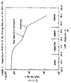
- Fig. 1 is a generalized illustration of the storage modulus, E', as a function of temperature at about 1 Hz for an appropriate phase change ink composition of the present invention.
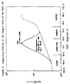
- Fig. 2 is a generalized temperature profile of tan ⁇ for a phase change ink composition of the present invention.
- Fig. 3 is a DMA curve for the formulation of Example 1.
- FIGS. 4-8 are DMA curves for the formulations of Example 2.
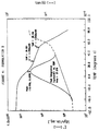
- FIGS. 9, 10 and 12 are plots of compressive yield stress versus temperature for the formulations of Examples 1 and 3.
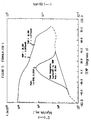
- FIG. 11 is a plot of the compressive yield stress versus strain rate for the formulation B of Example 2.
- This invention comprises selective phase change ink compositions for use in a process by which such compositions are indirectly applied via an intermediate transfer surface to a final receiving surface or substrate.
- the selective phase change ink compositions of the instant invention comprise a phase change ink colorant composition and a modified phase change ink carrier composition.
- the modified phase change ink carrier composition is formulated so that it produces a selective ink composition having predetermined fluidic and mechanical properties which meet the parameters required for the indirect application via an intermediate transfer surface of the ink composition to a final receiving substrate.
- the modified base phase change ink carrier composition typically comprises a fatty amide-containing material.
- the fatty amide-containing material of the modified phase change ink carrier is a tetra-amide compound.
- the preferred tetra-amide compounds for producing the modified phase change ink carrier composition are dimer acid-based tetra-amides which preferably include the reaction product of a fatty acid, a diamine (ethylene diamine) and a dimer acid.
- the term "dimer acid” preferably means a hydrogenated oleic acid dimer product.
- a preferred example of such a dimer acid is a product known as Empol 1008 Dimer Acid, manufactured by the Emery Division of Henkel Corporation of Cincinnati, Ohio.
- dimer acid-based tetra-amides are produced by Union Camp and comprise the reaction product of ethylene diamine, dimer acid, and the following fatty acids: decanoic acid (Union Camp X3203-23), myristic acid (Union Camp X3202-56), stearic Acid (Union Camp X3138-43, X3164-23, X3202-44, X3202-46, X3222-655, X3261-37, X3261-53, and X3290-72), and docosanoic acid (Union Camp X3202-36).
- decanoic acid Union Camp X3203-23
- myristic acid Union Camp X3202-56
- stearic Acid Union Camp X3138-43, X3164-23, X3202-44, X3202-46, X3222-655, X3261-37, X3261-53, and X3290-72
- docosanoic acid Union Camp X3202-36
- the most preferred dimer acid based tetra-amide is the reaction product of dimer acid, ethylene diamine and stearic acid in the stoichiometric ratio of 1:2:2.
- Stearic acid is the preferred fatty acid reactant because its adduct with dimer acid and ethylene diamine has the lowest viscosity of the dimer acid based tetra-amides. Its ingredients also are the most readily available and, therefore, lowest in cost.
- the fatty amide-containing material can also comprise a mono-amide.
- the phase change ink carrier composition comprises both a tetra-amide compound and a mono-amide compound.
- the mono-amide compound typically comprises either a primary or secondary mono-amide, but is preferably a secondary mono-amide.
- stearamide such as Kemamide S, manufactured by Witco Chemical Company
- behenyl benenamide Kemamide EX-666
- stearyl stearamide Kemamide S-230 and Kemamide EX-672
- stearyl stearamide is the mono-amide of choice in producing the modified phase change ink carrier composition of the present invention.
- the preferred fatty amide-containing compounds of this invention comprise a plurality of fatty amide materials which are compatible with each other. Typically, even when a plurality of fatty amide-containing compounds are employed to produce the modified phase change ink carrier composition, the modified carrier composition has a substantially single melting point transition.
- the melting point of the phase change ink carrier composition is preferably at least about 85° C.
- the preferred modified phase change ink carrier composition comprises a tetra-amide and a mono-amide.
- the weight ratio of the tetra-amide to the mono-amide in the preferred instance is from about 2:1 to about 1:10, and more preferably, from about 1:1 to about 1:3.
- modifying agents can be added to a phase change ink carrier composition.
- a preferred modifying agent includes certain tackifiers.
- the preferred tackifiers encompass those which are compatible with fatty amide-containing materials.
- KE-311 Resin a glycerol ester of hydrogenated abietic (rosin) acid made by Arakawa Chemical Industries, Ltd.
- Foral 85 a glycerol ester of hydrogenated abietic (rosin) acid
- Foral 105 a pentaerythritol ester of hydroabietic (rosin) acid, Cellolyn 21, a hydroabietic(rosin) alcohol ester of phthalic acid, all manufactured by Hercules Chemical Company, Nevtac 2300 and Nevtac 80, synthetic polyterpene resins manufactured by Neville Chemical Company, and Wingtack 86, a modified synthetic polyterpene resin manufactured by Goodyear Chemical Company.
- the most preferred tackifier is KE-311.
- plasticizers are suitable for this purpose.
- the preferred plasticizer is Santicizer 278, which is the mixed di-ester of phthalic acid with benzyl alcohol and "Texanol”.
- phase change ink carrier composition may be combined with additives.
- antioxidants are added for preventing discoloration of the carrier composition.
- the preferred antioxidant materials can include Irganox 1010 manufactured by Ciba Geigy; and Naugard 76, Naugard 512, and Naugard 524 manufactured by Uniroyal Chemical Company. However, the most preferred antioxidant is Naugard 524.
- phase change ink compositions with mechanical and fluidic properties similar to those outlined above.
- these other materials can include paraffins, microcrystalline waxes, polyethylene waxes, ester waxes, oligomers or low molecular weight polymers and copolymers such as EVA, ethylene/acrylic acid copolymers, EVA/acrylic acid copolymers, ionomers, copolymers of acrylic acid with polyamides, and the like.
- the phase change ink carrier composition comprises a tetra-amide and a mono-amide compound and a modifying agent which includes a tackifier, a plasticizer, and an antioxidant.
- the preferred compositional ranges of this phase change ink carrier composition are as follows: from about 10 to about 50 weight percent of a tetra-amide compound, from about 30 to about 80 weight percent of a mono-amide compound, from about O to about 40 weight percent of a tackifier, from about O to about 30 weight percent of a plasticizer and about O to about 2 percent of an antioxidant.
- phase change inks Another important property of phase change inks is viscosity.
- the viscosity of the molten ink must be matched to the requirements of the ink jet device and optimized versus other physical properties of the ink.
- the viscosity of the phase change ink is measured on a Ferranti-Shirley cone plate viscometer with a large cone.
- the viscosity of the phase change ink carrier composition at 140° C, and in turn the ink composition of this invention is from about 5 x 10 -3 Pa.s to about 3 x 10 -2 Pa.s (about 5 to about 30 centipoise), more preferably from about 1 x 10 -2 Pa.s to about 2 x 10 -2 Pa.s (about 10 to about 20 centipoise), and most preferably from about 1.1 x 10 -2 to about 1.5 x 10 -2 Pa.s (about 11 to about 15 centipoise).
- the subject phase change ink formed from the phase change ink carrier composition exhibit excellent physical properties.
- the subject phase change ink unlike prior art phase change inks, exhibits a high level of lightness, chroma, and rectilinear light transmissivity when utilized in a thin film of substantially uniform thickness, so that color images can be conveyed using overhead projection techniques.
- the preferred phase change ink compositions exhibit the preferred mechanical and fluidic properties mentioned above when measured by DMA, compressive yield testing and viscometry, and more importantly, work well when used in the indirect printing process described in the previously mentioned co-pending European Patent Application No 93 309426.0.
- the transmission spectra for each of the phase change inks used in the process of this invention were evaluated on a commercially available spectrophotometer, the ACS Spectro-Sensor II, in accordance with the measuring methods stipulated in ASTM lE805 (Standard Practice of Instrumental Methods of Color or Color Difference Measurements of Materials) using the appropriate calibration standards supplied by the instrument manufacturer.
- measurement data were reduced, via tristimulus integration, following ASTM E308 (Standard Method for Computing the Colors of Objects using the CIE System) in order to calculate the 1976 CIE L* (Lightness), a* (redness-greenness), and b* (yellowness-blueness) CIELAB values for each phase change ink sample.
- ASTM E308 Standard Method for Computing the Colors of Objects using the CIE System
- the values for CIELAB Psychometric Chroma, C* ab , and CIELAB Psychometric Hue Angle were calculated according to publication CIE15.2, Colorimetry (Second Edition, Central Bureau de la CIE, Vienna, 1986).
- phase change ink used in the process of the present invention is such that thin films of substantially uniform thickness exhibit a relatively high L* value.
- a substantially uniform thin film of about 2 x 10 -5 m (about 20 micron) thickness of the phase change ink of this invention preferably has an L* value of at least about 65, more preferably at least about 75, and most preferably at least about 85.
- phase change inks used herein have a relatively high C*ab value when measured as a thin film of substantially uniform thickness.
- conventional phase change inks have had a very low degree of rectilinear light transmissivity, even in thin films of substantially uniform thickness.
- the phase change ink composition used in the process of this invention has C*ab values, when applied as a substantially uniform thin film of about 1 x 10 -5 m (about 10 micron) thickness with subtractive primary yellow, magenta and cyan color phase change ink compositions, that preferably are at least about 40 for said yellow ink composition, at least about 65 for said magenta ink composition, and at least about 30 for the cyan ink composition.
- the black color phase change ink component be at a minimum light transmissivity level so that the color intensity of the ink is maximized.
- the L* value of a substantially uniformly thin film of about 1 x 10 -5 m (about 10 microns) thickness of a black color phase change ink is preferably not more than about 35, more preferably not more than about 30, and most preferably not more than about 25.
- abrasion resistance is determined by testing a finished print sample of the phase change ink produced from the carrier composition in a Teledyne Taber Abrader, Model 5130, utilizing CS-230 Abrasion wheels loaded with 500 gram weights. The abrasion wheels are resurfaced after each sample with an S-11 resurfacing disk. Samples printed on paper were tested according to ASTM D406(F84 (Standard Test Method For Abrasion Resistance of Organic Coatings by the Taber Abrader). Samples printed on light transmissive thin films were tested using ASTM D1304Q-85 (Standard Test Method For Resistance of Transparent Plastics to Surface Abrasion). Print samples were tested as described above, and the results of those tests demonstrated excellent abrasion resistance.
- a further test employed to evaluate the durability of phase change inks and ink carrier compositions is an offset transfer or blocking test. This determines whether the phase change ink printed on a substrate will adhere to an adjacent substrate at ambient or elevated temperatures when the printed products are stacked one on top of the other.
- the blocking test is conducted using an indirect transfer method by printing samples of the phase change ink produced from the carrier composition onto a paper or thin film substrate and placing that substrate in a manila folder under a one pound piece of aluminum, about 0.216m (about 8.5 inches) wide and about 0.279m (about 11 inches) long to evenly distribute the weight of a 4.536 kg (10 pound) block. These printed samples are placed in an oven for 24 hours at a constant temperature of about 60° C. Print samples of the phase change ink of the present invention, subjected to the above described blocking test showed no blocking.
- the above-defined DMA properties of the phase change ink compositions were experimentally determined. These dynamic measurements were done on the Rheometrics Solids Analyzer (RSA II) manufactured by Rheometrics, Inc. of Piscataway, New Jersey, using a dual cantilever beam geometry. The dimensions of the sample were about 2.0 ⁇ 1.0 mm thick, about 6.5 ⁇ 0.5 mm wide, about 54.0 ⁇ 1.0 mm long. A time/cure sweep was carried out under a desired force oscillation or testing frequency of about 1 Hz and an auto-strain range of about 1.0 X 10 -5 % to about 1%. The temperature range examined was about -60° to about 90° C.
- the preferred phase change ink compositions typically are (a) ductile or flexible at a temperature of about -10 to about 80° C, (b) have a temperature range for the glassy region from about -100 to 40° C, the value of E' being from about 1.5 x 10 8 to 1.5 x 10 10 Pa (about 1.5 X 10 9 to 1.5 X 10 11 dynes/cm 2 ), (c) have a temperature range for the transition region from about -50 to about 60° C, (d) have a temperature range for the rubbery region of E' from about -10 to 100° C, the value of E' being from about 1.0 x 10 5 to about 1.0 x 10 10 Pa (about 1.0 X 10 6 to about 1.0 X 10 11 dynes/cm 2 ), and (e) have a temperature range for the terminal region of E' from about 30 to about 160° C.
- the glass transition temperature range of the phase change ink compositions are from about -40 to about 40° C
- the temperature range for integrating under the tan ⁇ peak of the phase change ink composition is from about -80 to about 80° C with integration values ranging from about 5 to about 40
- the temperature range for the peak value of tan ⁇ of the phase change ink is from about -40 to about 40° C with a tan ⁇ of about 1.0 X 10 -2 to about 1.0 X 10 at peak.
- FIG 1 shows a representative plot of the storage modulus, E', as a function of temperature at about 1 Hz for an appropriate phase change ink composition for use in the printing process of the present invention.
- the curve will be divided up into four distinct regions: glassy, transition, rubbery, and terminal.
- the ink behaves similar to a hard, brittle solid i.e., E' is high, about 1 x 10 9 Pa (about 1 X 10 10 dynes/cm 2 ). This is because in this region there is not enough thermal energy or a long enough time for the molecules to move. This region needs to be well-below room temperature so the ink will not be brittle and affect the room temperature performance on paper.
- the transition region is characterized by a large drop in the storage modulus of about one order of magnitude. This is because the molecules have enough thermal energy or time to undergo conformational changes. In this region, the ink changes from being hard and brittle to being tough and leathery.
- the rubbery region describes a slightly decreasing plateau. In this region, there is a short term elastic response to the deformation that gives the ink its flexibility. It is theorized that the impedance to motion or flow in this region is due to entanglements of molecules or physical cross-links from crystalline domains. Fine tuning of the ink to get this plateau in the appropriate temperature range for good transfer and fixing and room temperature performance is of great importance in formulating these phase change ink compositions.
- the rubbery region encompasses the ink in both its malleable state during the transfer and fixing or fusing step and its final ductile state on the final receiving substrate.
- FIG 2 gives the general temperature profile of tan ⁇ for a phase change ink composition for use in the printing process of the present invention.
- tan ⁇ is small.
- the peak of the damping curve occurs in the transition region and indicates the T g of the material.
- the area under the tan ⁇ curve gives an indication of the relative toughness of the ink, which is a measure of the energy dissipated during deformation. Since tan ⁇ is equal to the loss modulus divided by the storage modulus, it is not necessary to specify the profiles of both the tan ⁇ and loss modulus.
- phase change ink compositions were also analyzed by compressive yield testing.
- the compressive yield strength measurements were done on an MTS SINTECH 2/D mechanical tester manufactured by MTS Sintech, Inc. of Cary, North Carolina, using small cylindrical sample blocks. The dimensions of a typical sample are about 19.0 ⁇ 1.0 mm X about 19.0 ⁇ 1.0 mm. Isothermal yield stress was measured as a function of temperature (about 25° to about 80° C) and strain rate. The material was deformed up to about 40%.
- YS mT + I
- YS which is a function of temperature
- m the slope
- T the temperature
- I the intercept
- the preferred yield stress values are described by m as being from about -62.053 ⁇ -13.790 kPa (about -9 ⁇ -2 psi)/° C to about -248.211 ⁇ -13.790 kPa (about -36 ⁇ -2 psi)/° C and I as being from about 5.516 MPa ⁇ 689.48 kPa (about 800 ⁇ 100 psi) to about 15.168 MPa ⁇ 689.48 kPa (about 2200 ⁇ 100 psi).
- m is about -206.843 ⁇ -13.790 kPa (about -30 ⁇ -2 psi)/° C and I is about 11.645 MPa ⁇ 689.48 kPa (about 1700 ⁇ 100 psi).
- the preferred stress values are described by m as being from about -41.368 ⁇ - 13.790 kPa (about -6 ⁇ -2 psi)/° C to about -248.211 ⁇ -13.790 kPa (about -36 ⁇ -2 psi)/° C and I as being from about 5.516 MPa ⁇ -689.48 kPa (about 800 ⁇ 100 psi) to about 1.103 MPa ⁇ 689.48 kPa (about 1600 ⁇ 100 psi).
- m is about -62.053 ⁇ -13.790 kPa (about -9 ⁇ -2 psi)/° C and I is about 6.550 MPa ⁇ 689.48 kPa (about 950 ⁇ 100 psi).
- the ink utilized in the process and system of the instant invention is preferably initially in solid form and is then changed to a molten state by the application of heat energy to raise the temperature from about 85° C to about 150° C. Elevated temperatures above this range will cause degradation or chemical breakdown of the ink.
- the molten ink is then applied in raster fashion from the ink jets in the printhead to the exposed surface of the liquid layer forming the intermediate transfer surface, where it is cooled to an intermediate temperature and solidifies to a malleable state in which it is transferred to the final receiving surface via a contact transfer by entering the nip between the pressure and fusing roller and the liquid layer forming the intermediate transfer surface on the support surface or drum.
- This intermediate temperature where the solidified ink is maintained in its malleable state is between about 30° C to about 80° C.
- the pressure exerted on the ink image is between about 68.948 to about 13789.514 kPa (about 10 to about 2000 psi) more preferably between about 3.447 to about 6.895 MPa (about 500 to about 1000 psi), and most preferably between about 5.171 to about 5.861 MPa (about 750 to about 850 psi).
- the pressure must be sufficient to have the ink image adhere to the final receiving substrate and be sufficiently deformed to ensure that light is transmitted through the ink image rectilinearly or without significant deviation in its path from the inlet to the outlet, in those instances when the final receiving substrate is a transparency.
- the ink image is cooled to ambient temperature of about 20° to about 25° C.
- the ink comprising the ink image must be ductile, or be able to yield or experience plastic deformation without fracture when kept above the glass transition temperature. Below the glass transition temperature the ink is brittle.
- the temperature of the ink image in the ductile state is between about -10° C and to about the melting point, or less than about 85° C.
- phase change ink composition can be effectively applied to an underlying substrate by direct ink jet printing techniques, such as described in Example 1 of U.S. 4,889,560, that same phase change ink composition may not be effectively applied by the indirect ink jet printing techniques of the present invention.
- phase change ink ingots of the subtractive primary colors were produced as follows:
- the phase change ink carrier composition was prepared from 58 grams of Kemamide S-180, 32 grams of Unirez X37-51-15 (a dimer acid-based tetraamide material manufactured by Union Camp and formed by the reaction of one mole of dimer acid, two moles of ethylene diamine, and two moles of stearic acid), and 10 grams of KE-311 Resin which were added to a 500 ml. beaker and heated with stirring to a temperature of about 120° C. After a homogeneous solution of the materials was achieved, the molten phase change ink carrier composition was filtered through a heated Mott apparatus using Whatman #3 filter paper and a pressure of 15 psi.
- the molten phase change ink carrier was placed in a beaker at about 105° C. 1% by weight of Orasol Yellow 46N colorant from Ciba Geigy was added to the mixture, which was then stirred at about 105° C for about 1 hour.
- the resulting ink composition was filtered using Whatman #3 filter paper in the heated Mott apparatus at about 110° C. The filtrate was poured into molds and allowed to solidify to form solid ink sticks.
- the inks are placed in a phase change color printer and applied from an ink jet printhead heated to about 140° C to a liquid intermediate transfer surface supported by about a 0.105m (about a 4.13 inch) diameter support drum.
- the raster printed image is contact transferred in a pagewise fashion to a sheet of Hammermill Laser Print high resolution electronic publishing grade paper by pressure in a nip formed between a fusing roller and the support drum while being maintained at a temperature of about 50° C.
- the image is not fully transferred and is weak and crumbly. The image cracks upon folding of the paper at room temperature.
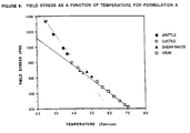
- FIG. 9 is a plot of the yield stress as a function of temperature at a constant strain rate of approximately 0.7 sec -l for Formulation A.
- the ink composition is brittle in compression. This indicates that it would not be very flexible or ductile and would tend to crack upon folding of the final receiving substrate.
- the composition is ductile. This is too narrow of a range for efficient use in the indirect printing process.
- the ink starts to show signs of shear banding.
- the mechanical properties of the ink start to deteriorate beyond about 50° C., which is characterized by a weak, crumbly behavior of the ink. This is highly undesirable in the indirect printing process using an intermediate transfer surface since the ink, once fused under these conditions, does not have the cohesive strength for efficient transfer.
- the yield stresses for this formulation are extremely high. This is undesirable because relatively high pressure is needed to fuse the ink during transfer.
- This example demonstrates a formulation identified as Formulation B, which meets the flexibility and toughness standards not achieved by the phase change ink composition of Example 1 of U.S. 4,889,560.
- the formulation illustrates a hot melt ink that is flexible at room temperature and can be transferred and fixed to a final receiving substrate up to about 50° C.
- the ink was formulated according to the procedure followed in Example I, using the following ingredients: Ingredients Weight % Kemamide S-180 41.5 Tetra-amide 21.5 KE-311 27.5 Santicizer-278 9.5
- the DMA curve for Formulation B is given in Figure 4.
- the T g of the ink is about 8.5° C, so it should be flexible at room temperature.
- E' of about one order in magnitude at the T g .
- the modulus is lower than that of Formulation A in Example 1, indicating that less energy is needed to yield and spread the ink during the transfer and fixing steps, as is evidenced by the compression testing results given below.
- the area under the tan ⁇ peak is 27.7, which is about three times higher than Formula A in Example 1 and indicates that the ink will be much tougher.
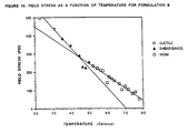
- Figure 10 is a plot of the yield stress as a function of temperature at a constant strain rate of approximately 0.7 sec -l for Formulation B. From room temperature up to about 35° C, Formulation B is ductile. This indicates that this composition is flexible at room temperature, and when printed on paper and transparency substrates it does not crack upon their being folded. The shear bandings occur in the range of about 35° to about 50° C and the ink becomes weak and crumbly beyond about 50° C. The yield stress for this formulation is lower than Formulation A, which is desirable for the indirect printing process.
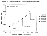
- Figure 11 is a plot of yield stress as a function of reduced strain rate for the referenced temperature of about 45° C for Formulation B.
- the composition is weak and crumbly.
- the reduced data indicates that for every decade in rate there is a gain of at least about 5° C for each transition. Since these compressive yield tests were carried out at least 2 orders of magnitude lower in rate than the rate used during the indirect printing process with a liquid intermediate transfer surface, the ink is in the safe ductile-shear banding zone instead of the shear banding-weak zone during the transfer and fixing process of the indirect printing process.
- the inks were placed in a phase change color printer, heated to about 140° C, and applied from an ink jet printhead to a liquid intermediate transfer surface supported by about a 0.105m (about a 4.13 inch) diameter support drum.
- the raster printed image was contact transferred in a pagewise fashion to a sheet of Xerox 4024 plain paper by pressure in a nip formed between a fusing roller and the support drum while being maintained at a temperature of about 50° C.
- the image was fully transferred and was well fused into a uniform layer with no indication of cohesive failure upon microscopic inspection.
- the image revealed no evidence of cracking upon folding of the paper at room temperature.
- Formulation F represents the formulation that has the best blocking characteristics of the inks tested and which is flexible at room temperature under normal slow folding rates, is ductile and retains its cohesive strength under high transfer and fixing temperatures and rates, possesses low yield stress at the transfer and fixing range of between about 40° and about 70° C, and has high yield stresses at room temperatures for good durability.
- the ink was formulated according to the procedure followed in Example 1, using the following ingredients: Ingredients Weight % Kemamide S-180 47.0 Tetra-amide 21.5 KE-311 27.0 Santicizer-278 4.5
- the dyes were added to the ink carrier composition in the same quantity as given in Example 2 following the procedure of Example 1.
- Example 2 The resulting inks were placed in a phase change color printer and run according to the description in Example 2.
- Figure 12 is a plot of yield stress as a function of temperature for Formulation F.
- the composition is ductile from at least about 25° C to about 55° C.
- the yield stresses in this range approach the high values of Formulation A.
- the composition should have far better blocking properties and durability than Formulation B.
- From about 55° C. to about 70° C. the ink starts to form shear bands, but still retains cohesive strength.
- the yield stresses in this range are approximately the same as Formulation B. Therefore, high pressure is not needed to fuse this ink during the indirect printing process using an intermediate transfer surface.
- the DMA curve for Formulation F is given in Figure 8.
- the T g of the ink is about 16° C, so it is still flexible or ductile at room temperature.
- E' of about one order in magnitude at the T g .
- the modulus is lower than that of Formula A, indicating that less energy is needed to yield and spread the ink during the transfer and fixing process.
- the reduction in modulus is not as abrupt as that for Formulation B in Example 2, indicating there is still some mechanical strength up to about 70° C.
- the area under the tan ⁇ peak is about 24, which is only slightly lower than Formula B, and will result in an ink with similar toughness.
- Formulation C illustrates a hot melt ink with the rubbery plateau extended to about 70° C and still retains most of the same properties as Formulation B in Example 2.
- the ink was formulated according to the ingredients for the dyes in Example 2 and according to the procedure followed in Example 1, using the following ingredients: Ingredients Weight % Kemamide S-180 50 Tetra-amide 30 Cellolyn-21 20
- the DMA curve for Formulation C is given in Figure 5.
- the DMA data show that the T g is slightly lower than that for Formulation B, the modulus is slightly higher than Formulation B in Example 2, the rubbery plateau has been extended to about 70° C, and the area under the tan ⁇ is slightly lower.
- the room temperature performance of the ink should be similar to Formulation A of Example 1.
- the temperature limit for cohesive failure of the ink is slightly lower than that for Formulation B in Example 2.
- the four colors (cyan, magenta, yellow and black) of the ink were placed in a phase change color printer and run according to the description in Example 2, except that the transfer and fixing temperature range was about 2° C to about 5° C higher.
- the quality of the printed image was comparable to that of Formulation B in Example 2.
- Formulation D illustrates a hot melt ink with a higher T g , but still has the same extension of the rubbery plateau as Formulation C in Example 4.
- the ink carrier composition was formulated according to the procedure followed in Example 1, using the following ingredients: Ingredients Weight % Kemamide S-180 49.0 Tetra-amide 21.5 KE-311 27.0 Santicizer-278 2.5
- the DMA curve for Formula D is given in Figure 6.
- the DMA data show that the T g is higher than that for Formula C of Example 4 by about 19° C, the extension on the rubbery plateau is still the same, and the area under tan ⁇ is lightly lower.
- the room temperature performance of this ink is less flexible, but more energy dissipative and therefore tougher because the tan ⁇ peaks at about room temperature.
- Formulation E illustrates a hot melt ink with an extremely low T g .
- the ink carrier composition was formulated according to the procedure followed in Example 1, using the following ingredients: Ingredients Weight % Kemamide S-180 31.0 Tetra-amide 21.5 KE-311 27.5 Santicizer 20.0
- the DMA curve for Formulation E is given in Figure 7.
- the T g of the formulation is about -7.3° C, which is well below room temperature.
- the ink is very flexible at room temperature.
- the ink is the toughest of all of the formulations, which is obvious from the high value of the area under the tan ⁇ peak.
- the profile of the modulus curve shows two distinct transitions, giving one plateau for room temperature performance and another at a lower modulus for easier transfer and fixing.
- This example demonstrates the high chroma (C* ab ) and lightness (L*) values of the phase change ink compositions of the present invention.
- the ink carrier composition employed with the colorant to form the ink composition of the present invention can be a low viscosity semicrystalline or crystalline amide wax, an ester wax, a polyethylene wax, a microcrystalline wax or a paraffin in combination with a hydrocarbon or resin based amorphous material, or an oligomer, or low molecular weight polymer or copolymer, or a tackifier, or a plasticizer and combinations thereof.
- phase change ink formulations of the invention may be employed in processes of printing upon a substrate in which processes an intermediate transfer surface is used.
- Figures 13 to 15 illustrate diagrammatically an imaging apparatus for use in such a process to transfer an inked image from an intermediate transfer surface to a final receiving substrate.
- a printhead 11 is supported by an appropriate housing and support elements (not shown) for either stationary or moving utilization to place an ink in the liquid or molten state on the supporting intermediate transfer surface 12 that is applied to the surface of the supporting surface 14.
- Intermediate transfer surface 12 is a liquid layer that is applied to the supporting surface 14, which is shown as a drum, but may also be a web, platen, or any other suitable design, by contact with an applicator, such as a metering blade, roller, web or the shown wicking pad 15 contained within applicator assembly 16.
- an applicator such as a metering blade, roller, web or the shown wicking pad 15 contained within applicator assembly 16.
- the supporting surface 14 may be formed from any appropriate material, such as metals including but not limited to aluminium, nickel or iron phosphate, elastomers including but not limited to fluoroelastomers, perfluoroelastomers, silicone rubber and polybutadiene, plastics including but not limited to polytetrafluorethylene loaded with polyphenylene sulfide, thermoplastics such as polyethylene, nylon and FEP (fluorinated ethylene propylene), thermosets such as acetals, or ceramics could be employed as long as the exposed surface is sufficiently rigid to deform the transferred image-forming ink 26 when the final receiving medium passes between it and the transfer and fixing roller 22 and sufficiently smooth so as not to interfere with the ability of the intermediate transfer surface or liquid layer to support the image-forming ink 26 of FIG 2.
- the preferred material is anodized aluminium.
- Applicator assembly 16 optionally contains a reservoir and wicking pad 15 for the liquid and most preferably contains a web and web advancing mechanism (both not shown) to periodically present fresh web for contact with the drum 14.
- Wicking pad 15 or the web is preferably any appropriate nonwoven synthetic textile with a relatively smooth surface.
- the web can be polyester.
- a preferred configuration can employ the smooth wicking pad 15 mounted atop a porous supporting material 18, such as a polyester felt. Both materials are available from BMP Corporation as BMP products NR90 and PE 1100-UL, respectively (BMP Corporation, c/o BMP America, 11625 Maple Ridge Road, Medina, New York, NY 14103, USA).
- Applicator apparatus 16 is mounted for retractable movement upward into contact with the surface of drum 14 and downwardly out of contact with the surface of the drum 14 and its liquid layer 12 by means of appropriate mechanism, such as an air cylinder or an electrically actuated solenoid.
- FIG 13 shows a final substrate guide 20 that passes the final receiving substrate 28, such as paper, from a positive feed device (not shown) and guides it through the nip formed by the opposing arcuate surfaces of the roller 22 and the intermediate transfer surface 12 supported by the drum 14.
- Stripper fingers 25 may be pivotally mounted to the imaging apparatus 10 to assist in removing any paper or other final receiving substrate media from the exposed surface of the liquid layer forming the intermediate transfer surface 12.
- Roller 22 has a metallic core, preferably steel, with an elastomeric covering that has a 40 to 45 Shore D rating. Suitable elastomeric covering materials include silicones, urethanes, nitriles, EPDM and other appropriately resilient materials.
- the elastomeric covering on roller 22 engages the final receiving substrate 20 on the reverse side to which the ink image 26 is transferred from the exposed surface of the liquid layer forming the intermediate transfer surface 12. This fuses or fixes the ink image 26 to the surface of the final receiving surface so that the ink image is spread, flattened and adhered.
- the ink utilized in the process and system of the instant invention is preferably initially in solid form and is then changed to a molten state by the application of heat energy to raise the temperature to about 85° C to about 150° C. Elevated temperatures above this range will cause degradation or chemical breakdown of the ink.
- the molten ink is then applied in raster fashion from the ink jets in the printhead 11 to the exposed surface of the liquid layer forming the intermediate transfer surface 12, where it is cooled to an intermediate temperature and solidifies to a malleable state in which it is transferred to the final receiving surface 28 via a contact transfer by entering the nip between the roller 22 and the liquid layer forming the intermediate transfer surface 12 on the support surface or drum 14.
- This intermediate temperature where the ink is maintained in its malleable state is between about 30° C to about 80° C .
- the solid malleable ink image Once the solid malleable ink image enters the nip, it is deformed to its final image conformation and adheres or is fixed to the final receiving substrate either by the pressure exerted against ink image 26 on the final receiving substrate 28 by the roller 22 alone, or by the combination of the pressure and heat supplied by heater 21 and/or heater 19. Heater 24 could optionally be employed to supply heat to facilitate the process at this point.
- the pressure exerted on the ink image 26 is between about 68.948 kPa to about 13.790 MPa (about 10 to about 2000 psi), more preferably between about 3.447 to about 6.895 MPa (about 500 to about 1000 psi), and most preferably between about 5.171 to about 5.860 MPa (about 750 to about 850 psi).
- the pressure must be sufficient to have the ink image 26 adhere to the final receiving substrate 28 and be sufficiently deformed to ensure that light is transmitted through the ink image rectilinearly or without significant deviation in its path from the inlet to the outlet, in those instances when the final receiving substrate is a transparency.
- the ink image is cooled to ambient temperature of about 20-25 degrees Centigrade.
- the ink comprising the ink image must be ductile, or be able to yield or experience plastic deformation without fracture when kept at a temperature above the glass transition temperature. Below the glass transition temperature the ink is brittle.
- the temperature of the ink image in the ductile state is between about -10° C and to about the melting point or less than about 85° C.
- FIG 15 diagrammatically illustrates the sequence involved when an ink image 26 is transferred from the liquid layer forming the intermediate transfer surface 12 to the final receiving substrate 28.
- the ink image 26 transfers to the final receiving substrate 28 with a small, but measurable quantity of the liquid in the intermediate transfer surface 12 attached thereto as an outer layer 29 .
- the average thickness of the transferred liquid layer 29 is calculated to be about 0.8 nanometers.
- the quantity of transferred liquid layer 29 can be expressed in terms of mass as being from about 0.1 to about 200 milligrams, and more preferably from about 0.5 to about 50 milligrams, and most preferably from about 1 to about 10 milligrams per page of final receiving substrate 28. This is determined by tracking on a test fixture the weight loss of the liquid in the applicator assembly 16 at the start of the imaging process and after a desired number of sheets of final receiving substrate 28 have been imaged.
- Some appropriately small and finite quantity of the liquid in the liquid layer forming the intermediate transfer surface 12 also is transferred to the final receiving substrate in areas adjacent the transferred ink image 26.
- This relatively small transfer of the liquid from the intermediate transfer surface 12 with the ink image 26 and to the non-imaged areas on the final receiving substrate 28 can permit as many as ten pages or more of the final receiving substrate 28 to be imaged before it is necessary to replenish the sacrificial liquid layer forming the intermediate transfer surface 12. Replenishment may be necessary after fewer final imaged copies, depending on the quality and nature of the final receiving surface 28 that is utilized.
- Transparencies and paper are the primary intended media for image receipt.
- plain paper is the preferred medium, such as that supplied by Xerox Corporation and many other companies for use in photocopy machines and laser printers. Many other commonly available office papers are included in this category of plain papers, including typewriter grade paper, standard bond papers, and letterhead paper. Xerox 4024 paper is assumed to be a representative grade of plain paper for the purposes of this invention.
- the thickness of the liquid layer forming the intermediate transfer surface 12 on the supporting surface or drum 14 can be measured, such as by the use of reflectance Fourier Transform infrared spectroscopy or a laser interferometer, it is theorized that the thickness can vary from about 5 X 10 -8 m to about 6 X 10 -5 m (about 0.05 microns to about 60 microns), more preferably from about 1 X 10 -7 m to about 5 X 10 -5 m (about 0.1 microns to about 50 microns), and most preferably from about 1 X 10 -6 m to about 1 X 10 -5 m (about 1 micron to about 10 microns).
- the thickness of the layer forming the intermediate transfer surface 12 can increase if rougher surfaced supporting surfaces or drums 14 are employed.
- the surface topography of the supporting surface or drum 14 can have a roughness average (R a ) of from about 25.4 nm (about 254 Angstroms) to about 2540 nm (about 25,400 Angstroms) (about 1 microinch to about 100 microinches), and a more preferred range of from about 127 nm to about 381 nm (about 5 to about 15 microinches).
- R a roughness average
- the image quality will degrade when a liquid layer thicker than about 6 X 10 -5 m (about 60 microns) is used to form the intermediate transfer surface 12.
- Suitable liquids that may be employed as the intermediate transfer surface 12 include water, fluorinated oils, glycol, surfactants, mineral oil, silicone oil, functional oils or combinations thereof.
- Functional oils can include, but are not limited to , mercapto-silicone oils, fluorinated silicone oils and the like.
- Heater device 19 may be a radiant resistance heater position as shown or more preferably, positioned internally within the drum 14. Heater devices 21 and 24 can also be employed in the paper or final receiving substrate guide apparatus 20 and in the fusing and fixing roller 22, respectively. Heater device 19 increases the temperature of the liquid intermediate transfer surface from ambient temperature to between about 25° C to about 70° C or higher. This temperature is dependent upon the exact nature of the liquid employed in liquid layer or intermediate transfer surface 12 and the ink employed. A more preferred range is between about 30° C to about 60° C, and a most preferred range is from about 45° C to about 52° C.
- Heater 21 preheats the final receiving medium prior to the fixation of the ink image by being set to heat between about 70° C to about 200° C, more preferably to between about 85° C and about 140° C, and most preferably to between about 110° C to about 130° C. It is theorized that heater 21 raises the temperature of the final receiving medium to between about 90° C and about 100° C. However, the thermal energy of the receiving media is kept sufficiently low so as not to melt the ink upon transfer to the final receiving substrate 28. Heater 24, when employed, heats the transfer and fixing roller 22 to a temperature of between about 25° C and about 200° C and alternatively may also be employed internally within roller 22.
- the ink used to form the ink image 26 preferably must have suitable specific properties for viscosity. Initially, the viscosity of the molten ink must be matched to the requirements of the ink jet device utilized to apply it to the intermediate transfer surface 12 and optimized relative to other physical and rheological properties of the ink as a solid, such as yield strength, hardness, elastic modulus, loss modulus, ratio of the loss modulus to the elastic modulus, and ductility.
- the viscosity of the phase change ink carrier composition has been measured on a Ferranti-Shirley Cone Plate Viscometer with a large cone.
- a preferred viscosity of the phase change ink carrier composition is from about 5 X 10 -3 Pa.s to about 3 X 10 -2 Pa.s (about 5 to about 30 centipoise), more preferably from about 1 X 10 -2 Pa.s to about 2 X 10 -2 Pa.s (about 10 centipoise to about 20 centipoise), and most preferably from about 1 X 10 -2 Pa.s to about 1.5 x 10⁻² Pa.s (about 11 centipoise to about 15 centipoise).
- the surface tension of suitable inks is between about 2.3 X 10 -4 and about 5 x 10 -4 N/centimeter (about 23 and about 50 dynes/centimeter).
- An appropriate ink composition is that described in U.S. Patent No. 4,889,560 (assigned to Tektronix, Inc.).
- Such an ink has a composition comprising a fatty amide-containing material employed as a phase change ink carrier composition and a compatible colorant.
- the fatty amide-containing material comprising a tetraamide compound and a monoamide compound.
- the phase change ink carrier composition is in a solid phase at ambient temperature and in a liquid phase at elevated operating temperature.
- the phase change ink carrier composition can comprise from about 10 to about 50 weight percent of a tetraamide compound, from about 30 to about 80 weight percent of a secondary mono-amide compound, from about 0 to about 40 weight percent of a tackifier, from about 0 to about 25 weight percent of a plasticizer, and from about 0 to about 10 weight percent of a viscosity modifying agent.
- the subject phase change ink used in the instant invention is formed from a phase change ink carrier composition which exhibits excellent physical properties.
- the subject phase change ink unlike prior art phase change inks, exhibits a high level of lightness, chroma, and transparency when utilized in a thin film of substantially uniform thickness. This is especially valuable when color images are conveyed using overhead projection techniques.
- the preferred phase change ink compositions exhibit the preferred mechanical and fluidic properties mentioned above when measured by dynamic mechanical analyses (DMA), compressive yield testing and viscometry. More importantly, these work well when used in the printing process of the instant invention utilizing a liquid layer as the intermediate transfer surface.
- DMA dynamic mechanical analyses
- the transmission spectra for each of the phase change inks used in the process of this invention were evaluated on a commercially available spectrophotometer, the ACS Spectro-Sensor II, in accordance with the measuring methods stipulated in ASTM 1E805 (Standard Practice of Instrumental Methods of Color or Color Difference Measurements of Materials) using the appropriate calibration standards supplied by the instrument manufacturer.
- measurement data were reduced, via tristimulus integration, following ASTM E308 (Standard Method for Computing the colors of Objects using the CIE System) in order to calculate the 1976 CIE L* (Lightness), a* (redness-greenness), and b* (yellowness-blueness), (CIELAB) values for each phase change ink sample.
- CIELAB CIELAB
- the values for Q hab ELAB Psychometric Chroma, C* ab , and CIELAB Psychometric Hue Angle were calculated according to publication CIE15.2, Colorimetry (Second Edition, Central Bureau de la CIE, Vienna, 1986).
- phase change ink carrier composition of the inks used in the process of the present invention is such that thin films of substantially uniform thickness exhibit a relatively high L* value.
- a substantially uniform thin film of about 2X 10 -5 m (about 20 micron) thickness of the phase change ink carrier composition of this invention preferably has an L* value of at least about 65, more preferably at least about 75, and most preferably at least about 85.
- phase change inks used herein have a relatively high C*ab value when measured as a thin film of substantially uniform thickness.
- conventional phase change inks have had a very low degree of rectilinear light transmissivity, even in thin films of substantially uniform thickness.
- the phase change ink composition used in the process of this invention has C*ab values, when applied as a substantially uniform thin film of about 10 micron thickness with subtractive primary yellow, magenta and cyan color phase change ink compositions, that preferably are at least about 40 for said yellow ink composition, at least about 65 for said magenta ink composition, and at least about 30 for the cyan ink composition.
- the black color phase change ink component be at a minimum light transmissivity level so that the color intensity of the ink is maximized. Accordingly, the L* value of a substantially uniform thin film of about 1 x 10 -5 m (about 10 microns) thickness of a black color phase change ink is preferably not more than about 35, more preferably not more than about 30, and most preferably not more than about 25.
- abrasion resistance is determined by testing a finished print sample of the phase change ink produced from the carrier composition in a Teledyne Taber Abrader, Model 5130, utilizing CS-230 Abrasion wheels loaded with 500 gram weights. The abrasion wheels are resurfaced after each sample with an S-11 resurfacing disk. Samples printed on paper were tested according to ASTM D406(F84 (Standard Test Method For Abrasion Resistance of Organic Coatings by the Taber Abrader). Samples printed on light transmissive thin films were tested using ASTM D1304Q-85 (Standard Test Method For Resistance of Transparent Plastics to Surface Abrasion). Print samples were tested as described above, and the results of those tests demonstrated excellent abrasion resistance.
- a further test employed to evaluate the durability of phase change inks and ink carrier compositions is an offset transfer or blocking test. This determines whether the phase change ink printed on a substrate will adhere to an adjacent substrate at ambient or elevated temperatures when the printed products are stacked one on top of the other.
- the blocking test is conducted using an indirect transfer method by printing samples of the phase change ink produced from the carrier composition onto a paper or thin film substrate and placing that substrate in a manila folder under a one pound piece of aluminum, about 0.216m (about 8.5 inches) wide and about 0.279m (about 11 inches) long to evenly distribute the weight of a 4.536 kg (10 pounds) block. These printed samples are placed in an oven for 24 hours at a constant temperature of about 60° C. Print samples of the phase change ink of the present invention, subjected to the above described blocking test showed no blocking.
- the preferred phase change ink compositions typically are (a) flexible at a temperature of about -10 to about 80° C, (b) have a temperature range for the glassy region from about -100 to 40° C, the value of E' being from about 1.5 x 10 8 to 1.5 x 10 10 Pa (about 1.5 X 10 9 to 1.5 X 10 11 dyne/cm 2 ), (c) have a temperature range for the transition region from about -30 to about 60° C, (d) have a temperature range for the rubbery region of E' from about -10 to 100° C, the value of E' being from about 1.0 x 10 5 to 1.0 x 10 10 Pa (about 1.0 X 10 6 to 1.0 X 10 11 dyne/cm 2 ), and (e) have a temperature range for the terminal region of E' from about 30 to about 160° C.
- the glass transition temperature range of the phase change ink compositions are from about -40 to about 40° C
- the temperature range for integrating under the tan ⁇ peak of the phase change ink composition is from about -80 to about 80° C with integration values ranging from about 5 to about 40
- the temperature range for the peak value of tan ⁇ of the phase change ink is from about -40 to about 40° C with a tan ⁇ of about 1.0 X 10 -2 to about 1.0 X 10 at peak.
- a representative plot of the storage modulus, E', as a function of temperature at 1 Hz for an appropriate phase change ink composition for use in the printing process of the present invention can be produced.
- the curve will be divided up into four distinct regions: glassy, transition, rubbery, and terminal.
- the ink behaves similar to a hard, brittle solid i.e., E' is high, about 1 x 10 9 Pa (about 1 X 10 10 dyne/cm 2 ). This is because in this region there is not enough thermal energy or long enough time for the molecules to move. This region needs to be well-below room temperature so the ink will not be brittle and affect the room temperature performance on paper.
- the transition region is characterized by a large drop in the storage modulus of about one order of magnitude. This is because the molecules have enough thermal energy or time to undergo conformational changes. In this region, the ink changes from being hard and brittle to being tough and leathery.
- the rubbery region describes a slightly decreasing plateau. In this region, there is a short term elastic response to the deformation that gives the ink its flexibility. It is theorized that the impedance to motion or flow in this region is due to entanglements of molecules or physical cross-links from crystalline domains. Fine tuning of the ink to get this plateau in the appropriate temperature range for good transfer and fixing and room temperature performance is of great importance in formulating these phase change ink compositions.
- the rubbery region encompasses the ink in both its malleable state during the transfer and fixing or fusing step and its final ductile state on the final receiving substrate.
- tan ⁇ for a phase change ink composition for use in the printing process of the present invention can be described as follows. In the glassy region, tan ⁇ is small. The peak of the damping curve occurs in the transition region and indicates the T g of the material. The area under the tan ⁇ curve gives an indication of the relative toughness of the ink, which is a measure of the energy dissipated during deformation. Since tan ⁇ is equal to the loss modulus divided by the storage modulus, it is not necessary to specify the profiles of both the tan ⁇ and loss modulus.
- phase change ink compositions were also analyzed by compressive yield testing.
- the compressive yield strength measurements were done on an MTS SINTECH 2/D mechanical tester manufactured by MTS Sintech, Inc. of Cary, North Carolina, using small cylindrical sample blocks. The dimensions of a typical sample are about 19.0 ⁇ 1.0 mm X about 19.0 ⁇ 1.0 mm. Isothermal yield stress was measured as a function of temperature (about 25° to about 80° C) and strain rate. The material was deformed up to about 40%.
- the preferred yield stress values are described by m as being from about -62.053 ⁇ - 13.790 kPa (about -9 ⁇ -2 psi)/° C to about -248.211 ⁇ -13.790 kPa (about -36 ⁇ -2 psi)/° C and I as being from about 5.516 MPa ⁇ 689.48 kPa (about 800 ⁇ 100 psi) to about 15.168 MPa ⁇ 689.48 kPa (about 2200 ⁇ 100 psi).
- m is about -206.843 ⁇ -13.790 kPa (about -30 ⁇ -2 psi)/° C and I is about 11.645 MPa ⁇ 689.48 kPa (about 1700 ⁇ 100 psi).
- the preferred stress values are described by m as being from about -41.368 ⁇ -13.790 kPa (about -6 ⁇ -2 psi)/° C to about -248.211 ⁇ -13.790 kPa (about -36 ⁇ -2 psi)/° C and I as being from about 5.516 MPa ⁇ - 689.48 kPa (about 800 ⁇ 100 psi) to about 1.103 MPa ⁇ 689.48 kPa (about 1600 ⁇ 100 psi).
- m is about -62.053 ⁇ -13.790 kPa (about -9 ⁇ -2 psi)/° C and I is about 6.550 MPa ⁇ 689.48 kPa (about 950 ⁇ 100 psi).
- the support surface or drum 14 has a layer of liquid intermediate transfer surface applied to its surface by the action of the applicator assembly 16.
- Assembly 16 is raised by an appropriate mechanism (not shown), such as an air cylinder, until the web 15 is in contact with the surface of the drum 14.
- the liquid is retained within a reservoir (not shown) within the assembly 16 and passes through the porous supporting material 18 until it saturates the web 15 to permit a uniform layer of desired thickness of the liquid to be deposited on the surface of the drum 14.
- the drum 14 rotates about a journalled shaft in the direction shown in FIG 1 while the heater 19 heats the liquid layer and the surface of the drum 14 to the desired temperature.
- Ink is applied to the exposed surface of the liquid intermediate transfer surface 12 by the printhead 11.
- the ink is applied in molten form, having been melted from its solid state form by appropriate heating means (not shown).
- the ink image 26 solidifies on the surface of the liquid by cooling to a malleable solid intermediate state as the drum continues to rotate, entering the nip formed by the roller 22 and the curved surface of the intermediate transfer surface 12 supported by the drum 14.
- the ink image 26 is deformed to its final image conformation and adhered to the final receiving surface 28 by being pressed there against.
- the ink image 26 is thus transferred and fixed to the final receiving surface 28 by the pressure exerted on it in the nip by the resilient or elastomeric surface of the roller 22.
- Stripper fingers 25 help to remove the imaged final receiving surface 28 from the liquid intermediate transfer surface 12 as the drum rotates.
- the ink image 26 then cools to ambient temperature where it possesses sufficient strength and ductility to ensure its durability.
- the applicator assembly 16 is actuated to raise upward into contact with the sacrificial intermediate transfer surface 12 to replenish the liquid forming the surface 12.
- Examples I to VI which follow are presented by way of example only, for the purposes of further illustration of the processes described with reference to Figures 13 to 15, and in particular to illustrate, by way of example only, the type of materials that can be successfully employed as the liquid intermediate transfer surface 12.
- a test fixture having a rotatably mounted about 0.102 mm (about 0.004 inch) thick drafting Mylar® plastic-covered aluminium drum with the matte side of the plastic facing out and a diameter of about 0.105m (about 4.13 inches) was positioned adjacent and in close proximity to a transfer and fusing roller of smaller diameter.
- a piezoelectrically driven printhead with phase change ink was positioned intermediate the drum and the transfer and fusing roller to deliver the primary colors of cyan, magenta, yellow and black to the exposed surface of a thin liquid layer of an intermediate transfer surface in raster fashion.
- the drum surface was hand coated with a liquid layer consisting of a mixture of about 79.5% by weight deionized water, about 20% by weight polyethylene glycol available as PEG 200 from Aldrich Chemical Company, and about 0.5% by weight of a fluorinated surfactant leveling agent commonly used in epoxies and available from the 3M Company under the tradename Fluorad FC-430 coating additive.
- This mixture was applied manually with a hand wipe available from Kimberly-Clark under the KAYDRY tradename to form the liquid intermediate transfer surface.
- the liquid layer was not entirely evenly applied to the drum surface since more thickly coated areas were noticably visible.
- the drum temperature was maintained at about 29° C to about 30° C.
- Paper was used as the final receiving substrate and was preheated by an external heating device with a temperature of about 100° C prior to being brought into contact with the transferred ink image.
- the transfer and fusing roller was also heated by an external heating device having a setpoint of about 120°C.
- liquid used to form the liquid intermediate transfer layer was an alkylphenyl polyglycol nonionic surfactant sold under the tradename Triton® X-100 by Spectrum Chemical Manufacturing Corporation of Gardenia, CA.
- Triton® X-100 by Spectrum Chemical Manufacturing Corporation of Gardenia, CA.
- Multiple copies of the same test image as in Example I were made, producing prints with somewhat tacky imaged areas.
- the print sheets were stacked one on top of another, some parts of the color image were transferred to the back of the overlying sheet of paper. It appeared as though the liquid used as the intermediate transfer layer penetrated the ink, partially plasticizing it. However, the inked image was successfully transferred from the liquid intermediate transfer surface to the paper.
- Example II The same test fixture and conditions as were utilized in Example I were employed, except that the fluorinated surfactant leveling agent sold under the tradename Fluorad FC-430 by 3M Corporation was employed as the liquid intermediate transfer surface. Two prints were made of the same full color test image as in Example I, with incomplete areas of transfer and a slightly tacky feeling in the printed areas.
- Example II The same test fixture and conditions as were utilized in Example I were employed, except that the liquid was applied in a wicking fashion with a wick/felt laminate applicator having a steel backing plate.
- the applicator had a force measured in air pressure of about 134.448 kPa (about 19.5 pounds per square inch) or about 6.804 kg (about 15 pounds) of force pressing it against the surface of the drum while applying the liquid layer.
- About 80 cubic centimeters of the liquid was placed into the applicator's reservoir. Five prints were made at the initial transfer and fixing speed of about 0.127 m per second (about 5 inches per second).
- the speed was increased by about 2.54 x 10 -2 m per second up to about 0.279 m per second (about 1 inch per second up to about 11 inches per second) until a total of 51 full color test prints of the type in Example I were made, including 2 transparencies made at a fixing speed of about 0.279 m per second (about 11 inches per second).
- Successful transfers were made at each transfer speed, but abrasion testing disclosed a gradual decrease in adherence of the images to the paper at the higher transfer speeds.
- Acceptable quality color prints were made up to transfer speeds of about 0.178 m per second (about 7 inches per second).
- Example II The same test fixture and conditions as were utilized in Example I were employed, except that the liquid was deionized water and was applied with a wick/felt laminate applicator in wicking fashion to a depth of about 1 mil.
- the applicator employed a steel backing plate.
- the liquid was intended to be delivered in a wicking fashion.
- the applicator delivered the liquid with about 18 pounds of force, forcing it against the surface of the drum while applying the liquid layer. About 80 cubic centimeters of the liquid was placed into the applicator's reservoir.
- Several prints were made of a four color bar pattern at an initial transfer and fixing speed of about 0.127 m per second (about 5 inches per second).
- the imaging surface speed was about 0.592 m per second (about 23.3 inches per second) with an application time at the imaging speed of about 800 microseconds.
- the ink drop ejection rate was set at about 7 Khz.
- the heater for the final receiving substrate, which in this case was paper, was set at about 100° C.
- the transfer and fixing roller's heater had a set point of about 120° C.
- the surface of the drum supporting the liquid layer was heated to between about 30° C to about 31° C, which caused some accelerated evaporation of the deionized water forming the liquid layer and required a relatively fast transfer speed. Successful four color transfers were made with each attempt, although it appeared that too thick of a layer of the deionized water would result in displaced dots.
- Example II A test fixture similar to that employed in Example I was used, except that the support drum was aluminum with an anodized surface finish.
- the drum had a diameter of about 0.101m (about 3.979 inches) and was externally heated across an air gap with a resistance heater that was linked to a control with an established setpoint of about 47° C.
- the heated drum surface was coated with silicone oil sold under the tradename Dow Corning 200.
- the oil was applied by being contacted for less than about 0.6 seconds during two rotations of the drum at an application speed of about 40 inches per second with an oil impregnated polyester web contained within a raisable cassette assembly. The web was pressed into contact with the drum surface with a force of about 10 pounds. Once the drum surface was fully coated with the liquid layer that forms the intermediate transfer surface, the cassette assembly was lowered out of contact with the drum.
- the paper final receiving substrate was preheated by a flat and flexible vulcanized silicone heater attached to the paper feed guides.
Claims (43)
- Ein Verfahren zum indirekten Auftragen einer selektiven Phasenumwandlungstintenzusammsetzung auf ein Substrat, wobei das Verfahren umfaßt:a) das Vereinen einer Phasenumwandlungstinten-Farbmittelzusammensetzung und einer modifizierten Phasenumwandlungstinten-Trägerzusammensetzung, um eine selektive Phasenumwandlungstintenzusammensetzung mit vorbestimmten Fluid- und Mechanikeigenschaften zu erzeugen, welche die erforderlichen Parameter zur Auftragung davon erfüllen;b) das Erhöhen der Temperatur dieser selektiven Phasenumwandlungstintenzusammensetzung auf eine erste, erhöhte Betriebstemperatur, um eine selektive Phasenumwandlungstintenzusammensetzung in flüssiger Phase zu bilden;c) das Vorsehen einer Zwischenübertragungseinrichtung bei einer zweiten, erhöhten Betriebstemperatur zum indirekten Auftragen der selektiven Phasenumwandlungstintenzusammensetzung in einer flüssigen Phase auf das Substrat;d) das Auftragen dieser selektiven Phasenumwandlungstintenzusammensetzung auf die Zwischenübertragungseinheit in einem vorbestimmten Muster und in einer flüssigen Phase;e) das Erzeugen des vorbestimmten Musters der selektiven Phasenumwandlungstintenzusammensetzung in einer festen Phase auf der Zwischenübertragungseinrichtung bei einer zweiten erhöhten Betriebstemperatur;f) das Übertragen der selektiven Phasenumwandlungstintenzusammensetzung von der Zwischenübertragungseinrichtung auf das Substrat; undg) das Fixieren der selektiven Phasenumwandlungstintenzusammensetzung auf dem Substrat, um ein gedrucktes Substrat zu erzeugen, wobei die selektive Phasenumwandlungstintenzusammensetzung (1) eine Druck-Formänderungsfestigkeit, die es ermöglichen wird, auf Druck zu fließen, wenn Druckkräfte darauf bei der zweiten erhöhten Temperatur angewendet werden, und eine ausreichende innere Kohäsionsfestigkeit, um einem Fehler zu widerstehen, wenn die selektiven Phasenumwandlungstintenzusammensetzung auf dem Substrat fixiert wird, und (2) einen hohen Duktilitätsgrad auf dem Substrat nach dem Fixieren aufweist, wobei dünne Filme von im wesentlichen gleichförmiger Dicke der selektiven Phasenumwandlungstintenzusammensetzung einen hohen Helligkeits- und Farbsättigungsgrad aufweisen.
- Ein Verfahren zum Drucken unter Verwendung einer Phasenumwandlungstintenzusammensetzung, wobei das Verfahren umfaßt:a. das Vereinen einer Phasenumwandlungstinten-Farbmittelzusammensetzung und einer modifizierten Phasenumwandlungstinten-Trägerzusammensetzung, um eine selektive Phasenumwandlungstintenzusammensetzung mit vorbestimmten Fluid- und Mechanikeigenschaften zu erzeugen, welche die erforderlichen Parameter zur indirekten Auftragung davon erfüllen;b) das Erhöhen der Temperatur dieser selektiven Phasenumwandlungstintenzusammensetzung auf eine erste, erhöhte Betriebstemperatur, um eine selektive Phasenumwandlungstintenzusammensetzung in flüssiger Phase zu bilden;c) das Vorsehen einer Zwischenübertragungseinrichtung bei einer zweiten, erhöhten Betriebstemperatur, welche niedriger ist als die erste Betriebstemperatur, zur Aufnahme der selektiven Phasenumwandlungstintenzusammensetzung in flüssiger Phase;d) das Auftragen der selektiven Phasenumwandlungstintenzusammensetzung in einer flüssigen Phase auf die Zwischenübertragungseinheit in einem vorbestimmten Muster;e) das Abkühlen des vorbestimmten Musters der selektiven Phasenumwandlungstintenzusammensetzung auf eine verformbare feste Phase auf der Zwischenübertragungseinrichtung auf eine Temperatur, die niedriger als die zweite erhöhte Betriebstemperatur ist;f) das Übertragen des vorbestimmten Musters der verformbaren selektiven Phasenumwandlungstintenzusammensetzung in fester Phase von der Zwischenübertragungseinrichtung auf das Substrat;g) das Fixieren des vorbestimmten Musters der selektiven Phasenumwandlungstintenzusammensetzung in verformbarer fester Phase auf dem Substrat, um ein gedrucktes Substrat zu erzeugen, wobei die selektive Phasenumwandlungstintenzusammensetzung (1) eine Druck-Formänderungsfestigkeit, die es ermöglichen wird, in verformbarer Weise zu fließen, wenn Druckkräfte darauf angewendet werden, und eine ausreichende interne Kohäsionsfestigkeit aufweisen, um einem Fehler zu widerstehen, wenn die selektive Phasenumwandlungstintenzusammensetzung auf dem Substrat fixiert wird; undh) das Abkühlen des vorbestimmten Musters der verformbaren festen Phasenumwandlungstintenzusammensetzung auf Raumtemperatur, so daß sie einen hohen Duktilitätsgrad auf dem Substrat nach dem Fixieren aufweist, wobei dünne Filme von gleichförmiger Dicke dieser auf Raumtemperatur abgekühlten selektiven Phasenumwandlungstinteuzusammensetzung einen hohen Helligkeits- und Farbsättigungsgrad aufweisen.
- Verfahren nach Anspruch 1 oder 2, wobei die Phasenumwandlungstintenzusammensetzung eine erhöhte Betriebstemperatur von wenigstens etwa 120°C und eine Viskosität von nicht mehr als etwa 3 x 10⁻² Pa.s (etwa 30 Centipois) aufweist.
- Verfahren nach jedem der Ansprüche 1 bis 3, worin die Temperatur während dem Fixieren der Phasenumwandlungstintenzusammensetzung auf das darunterliegende Substrat etwa 40 bis etwa 80°C beträgt.
- Verfahren nach jedem der vorhergehenden Ansprüche, worin die Phasenumwandlungstintenzusammensetzung bei einer Temperatur von etwa 10 bis etwa 30°C duktil ist.
- Verfahren nach jedem der vorhergehenden Ansprüche, worin die Phasenumwandlungstintenzusammensetzung für den Glasbereich von E' einen Temperaturbereich von etwa -100 bis 40°C aufweist, wobei der Wert E' von etwa 1,5 x 10⁸ bis etwa 1,5 x 10¹⁰ Pa (etwa 1,5 x 10⁹ bis etwa 1,5 x 10¹¹ Dyn/cm2) beträgt.
- Verfahren nach jedem der vorhergehenden Ansprüche, worin die Phasenumwandlungstintenzusammensetzung für den Übergangsbereich von E' einen Temperaturbereich von etwa -50 bis etwa 60°C aufweist.
- Verfahren nach jedem der vorhergehenden Ansprüche, worin die Phasenumwandlungstintenzusammensetzung für den gummiartigen Bereich von E' einen Temperaturbereich von etwa -10 bis etwa 100°C aufweist, wobei der Wert von E' von etwa 1,105 Pa bis etwa 1 x 10¹⁰ Pa (etwa 1,0 x 10⁶ bis etwa 1,0 x 10¹¹ Dyn/cm2) aufweist.
- Verfahren nach jedem der vorhergehenden Ansprüche, worin die Phasenumwandlungstintenzusammensetzung für den Endbereich von E' einen Temperaturbereich von etwa 30 bis etwa 160°C aufweist.
- Verfahren nach jedem der vorhergehenden Ansprüche, worin der L*-Wert eines im wesentlichen gleichförmigen dünnen Filmes von etwa 1 x 10⁻⁵ M (etwa 10 µm) Dicke einer schwarzen Farbe einer Phasenumwandlungstintenzusammensetzung, die aus der Phasenumwandlungstintenzusammensetzung erzeugt wird, nicht mehr als etwa 35 beträgt.
- Verfahren nach jedem der vorhergehenden Ansprüche, worin der L*-Wert eines im wesentlichen gleichförmig dünnen Filmes von etwa 2 x 10⁻⁵ M (etwa 20 µm) Dicke der Phasenumwandlungstintenzusammensetzung wenigstens etwa 65 beträgt.
- Verfahren nach jedem der vorhergehenden Ansprüche, worin die dünnen Filme gleichförmiger Dicke der Phasenumwandlungstintenzusammensetzung geradlinig spezifisch lichtdurchlässig sind.
- Verfahren nach jedem der vorhergehenden Ansprüche, worin der C*ab-Wert eines im wesentlichen gleichförmig dünnen Filmes von etwa 1 x 10⁻⁵ m (etwa 10 µm) Dicke einer Phasenumwandlungstintenzusammensetzung subtraktiver, primärer, gelber Farbe, die aus der Phasenumwandlungstintenzusammensetzung erzeugt ist, wenigstens etwa 40 beträgt, die einer Phasenumwandlungstintenzusammensetzung subtraktiver, primärer, Magentafarbe, welche aus der Phasenumwandlungstintenzusammensetzung erzeugt ist, wenigstens etwa 65 beträgt und die einer Phasenumwandlungstintenzusammensetzung subtraktiver, primärer Cyanfarbe, welche aus der Farbmittelzusammensetzung erzeugt ist, wenigstens etwa 30 beträgt.
- Verfahren nach jedem der vorhergehenden Ansprüche, worin der Glasübergangstemperaturbereich der Phasenumwandlungstintenzusammensetzung zwischen etwa -40 bis etwa 40°C liegt.
- Verfahren nach jedem der vorhergehenden Ansprüche, worin der Temperaturbereich für den Bereich unter dem

- Verfahren nach jedem der vorhergehenden Ansprüche, worin der Temperaturbereich für den Peak-Wert von


- Verfahren nach jedem der vorhergehenden Ansprüche, worin unter Nicht-Verfahrensbedingungen vor dem Erhöhen der Temperatur der selektiven Phasenumwandlungstintenzusammensetzung auf eine erste erhöhte Betriebstemperatur oder nach dem Erzeugen eines gedruckten Substrates der Deckkraft-Beanspruchungswert (YS) gemäß der Gleichung

- Verfahren nach Anspruch 17, worin n etwa -206,843 ± -13,790 kPa (etwa -30 ± -2 psi)/°C und I etwa 11,645 MPa ± 689,48 kPa (etwa 1.700 ± 100 psi) beträgt.
- Verfahren nach jedem der vorhergehenden Ansprüche, unter Verfahrensbedingungen von der Erhöhung der Temperatur der selektiven Phasenumwandlungstintenzusammensetzung auf eine erste erhöhte Betriebstemperatur zum Erzeugen eines gedruckten Substrates der Deckkraft-Beanspruchungswert (YS), gemäß der Gleichung

- Verfahren nach Anspruch 19, worin m etwa -62,053 ± -13,790 kPa (etwa -9 ± -2 psi)/°C und I etwa 6,550 MPa ± 689,48 kPa (etwa 950 ± 100 psi) beträgt.
- Eine selektive Phasenumwandlungstintezusammensetzung, umfassend eine Phasenumwandlungstinte-Farbmittelzusammensetzung und eine modifizierte Phasenumwandlungstinte-Trägerzusammensetzung, wobei die selektive Phasenumwandlungstintenzusammensetzung (a) vorbestimmte Fluid- und Mechanikeigenschaften, welche die erforderlichen Parameter zum Auftragen auf eine Zwischenübertragungsoberfläche bei einer erhöhten Temperatur in einem flüssigen Zustand und in einem vorbestimmten Muster erfüllt, bei der sie auf ein Substrat übertragen und fixiert wird, um ein gedrucktes Substrat zu erzeugen, (b) eine DruckFormänderungsfestigkeit, welche es der Tinte ermöglicht, in duktiler Weise zu fließen, wenn äußere Druckkräfte darauf angewendet werden, und eine ausreichende interne Kohäsionsfestigkeit, um einem Fehler zu widerstehen, wenn die Tinte auf dem Substrat fixiert wird, (c) einen hohen Duktilitätsgrad auf dem Substrat nach dem Übertragen und Fixieren und (d) einen hohen Helligkeits- und Farbsättigungsgrad für dünne Filme gleichförmiger Dicke davon, aufweist.
- Zusammensetzung nach Anspruch 21, worin die Phasenumwandlungstintenzusammensetzung bei einer Temperatur von etwa 10 bis etwa 30°C duktil ist.
- Zusammensetzung nach Anspruch 21 oder 22, worin die Phasenumwandlungstintenzusammensetzung für den Glasbereich von E' einen Temperaturbereich von etwa -100 bis etwa 40°C aufweist, wobei der Wert E' von etwa 1,5 x 10⁸ bis etwa 1,5 x 10¹⁰ Pa (etwa 1,5 x 10⁹ bis etwa 1,5 x 10¹¹ Dyn/cm2) bei einer gewünschten Versuchshäufigkeit aufweist.
- Zusammensetzung nach jedem der Ansprüche 21 bis 23, worin die Phasenumwandlungstintenzusammensetzung für den Übergangsbereich von E' einen Temperaturbereich von etwa -50 bis -60°C aufweist.
- Zusammensetzung nach jedem der Ansprüche 21 bis 24, worin die Phasenumwandlungstintenzusammensetzung für den Gummibereich von E' einen Temperaturbereich von etwa -10 bis 100°C aufweist, wobei der Wert E' von etwa 1,0 x 10⁵ bis etwa 1,0 x 10¹⁰ Pa (etwa 1,0 x 10⁶ bis etwa 1,0 x 10¹¹ Dyn/cm2) bei einer gewünschten Versuchshäufigkeit beträgt.
- Zusammensetzung nach jedem der Ansprüche 21 bis 25, worin die Phasenumwandlungstintenzusammensetzung für den Endbereich von E' einen Temperaturbereich von etwa 30 bis 160°C aufweist.
- Zusammensetzung nach jedem der Ansprüche 21 bis 26, worin der L*-Wert eines im wesentlichen gleichförmigen dicken Filmes von etwa 1 x 10⁻⁵ m (etwa 10 µm) Dicke einer schwarzen Farbe einer Phasenumwandlungstintenzusammensetzung, welche aus der Phasenumwandlungstintenzusammensetzung erzeugt ist, nicht mehr als 35 beträgt.
- Zusammensetzung nach jedem der Ansprüche 21 bis 27, worin der L*-Wert eines im wesentlichen gleichförmig dünnen Filmes von etwa 2 x 10⁻⁵ m (etwa 20 µm) Dicke der Phasenumwandlungstintenzusammensetzung wenigstens etwa 65 beträgt.
- Zusammensetzung nach jedem der Ansprüche 21 bis 28, worin die Filme gleichförmiger Dicke der Phasenumwandlungstintenzusammensetzung geradlinig spezifisch lichtdurchlässig sind.
- Zusammensetzung nach jedem der Ansprüche 21 bis 29, worin der C*ab-Wert eines im wesentlichen gleichförmig dünnen Filmes von etwa 10 x 10-5 m (etwa 10 µm) Dicke einer Phasenumwandlungstintenzusammensetzung substraktiver, primärer, gelber Farbe, welche aus der Phasenumwandlungstintenzusammensetzung erzeugt ist, wenigstens etwa 40 beträgt, die einer Phasenumwandlungstintenzusammensetzung subtraktiver, primärer, Magentafarbe, welche aus der Phasenumwandlungstintenzusammensetzung erzeugt ist, wenigstens etwa 65 beträgt und die einer Phasenumwandlungstintenzusammensetzung subtraktiver, primärer Cyanfarbe, welche aus der Farbmittelzusammensetzung erzeugt ist, wenigstens etwa 30 beträgt.
- Zusammensetzung nach jedem der Ansprüche 21 bis 30, worin der Glasübergangstemperaturbereich der Phasenumwandlungstintenzusammensetzung zwischen etwa -40 bis etwa 40°C liegt.
- Zusammensetzung nach jedem der Ansprüche 21 bis 31, worin der Temperaturbereich für die Fläche unter dem

- Zusammensetzung nach jedem der Ansprüche 21 bis 32, worin der Temperaturbereich für den Peak-Wert von

- Zusammensetzung nach jedem der Ansprüche 21 bis 33, worin unter Nicht-Verfahrensbedingungen, vor dem Erhöhen der Temperatur der selektiven Phasenumwandlungstintenzusammensetzung auf eine erste erhöhte Betriebstemperatur oder nach dem Erzeugen eines gedruckten Substrates der Deckkraft-Beanspruchungswert (YS) gemäß der Gleichung

- Zusammensetzung nach Anspruch 34, worin m etwa -206,843 ± -13,790 kPa (etwa -30 ± -2 psi)/°C und I etwa 11,645 MPa ± 689,48 kPa (etwa 1.700 ± 100 psi) beträgt.
- Zusammensetzung nach jedem der Ansprüche 21 bis 35, worin unter Verfahrensbedingungen von der Erhöhung der Temperatur der selektiven Phasenumwandlungstintenzusammensetzung auf eine erste erhöhte Betriebstemperatur zum Erzeugen eines gedruckten Substrates der Deckkraft-Beanspruchungswert (YS), gemäß der Gleichung

- Zusammensetzung nach Anspruch 36, worin m etwa -62,053 ± -13,790 kPa (etwa -9 ± -2 psi)/°C und I etwa 6,550 MPa ± 689,48 kPa (etwa 950 ± 100 psi) beträgt.
- Eine Tintenzusammensetzung zur Verwendung mit einem Tintenstrahldruckkopf, umfassend wenigstens ein Farbmittel und eine Tintenträgerzusammensetzung, wobei die Tintenzusammensetzung durch einen Temperaturbereich im Gummibereich von E' von etwa 10 bis 100°C, einen Wert von E' von 1,0 x 10⁶ bis 1,0 x 10¹¹ bei einer gewünschten Versuchshäufigkeit und einen Glasübergangstemperaturbereich von etwa -40 bis etwa 40°C gekennzeichnet ist, wobei E' durch die Gleichung

- Tintenzusammensetzung nach Anspruch 38, worin die Tintenträgerzusammensetzung aus der Gruppe ausgewählt ist, welche aus halbkristallinen oder kristallinen Amidwachsen niedriger Viskosität, einem Esterwachs, einem Polyethylenwachs, einem mikrokristallinen Wachs und Paraffin in Verbindung mit einem amorphen Material auf Kohlenwasserstoff- oder Harzbasis oder einem Oligomer oder einem Polymer oder Copolymer mit niedrigem Molekulargewicht oder einem Klebrigmacher oder einem Plastifizierer und Kombinationen davon ausgewählt ist.
- Tintenzusammensetzung nach Anspruch 39 oder 40, worin das Farbmittel in den primären Verfahrensfarben einen Satz von Farbmitteln umfaßt, die aus einer aus einem Farbstoff und einem Pigment bestehenden Gruppe ausgewählt sind.
- Tintenzusammensetzung nach jedem der Ansprüche 38 bis 40, worin unter Nicht-Verfahrensbedingungen vor dem Erhöhen der Temperatur der selektiven Phasenumwandlungstintenzusammensetzung auf eine erste erhöhte Betriebstemperatur oder nach dem Erzeugen eines gedruckten Substrates der Deckkraft-Beanspruchungswert (YS) gemäß der Gleichung

- Tintenzusammensetzung nach jedem der Ansprüche 38 bis 41, worin unter Verfahrensbedingungen vor dem Erhöhen der Temperatur der selektiven Phasenumwandlungstintenzusammensetzung auf eine erste erhöhte Betriebstemperatur zum Erzeugen eines gedruckten Substrates, der Deckkraft-Beanspruchungswert (YS) gemäß der Gleichung

- Phasenumwandlungstintenzusammensetzung, umfassend einen Farbmittelbestandteil und einen Trägerbestandteil, wobei die zwei Komponenten in Kombination eine Phasenumwandlungstintenfähigkeit verleihen und die Zusammensetzung ein duktiles, festes gummiartiges Material bei einer Temperatur im Bereich von etwa 10°C bis 30°C und eine Flüssigkeit einer Viskosität von nicht mehr als 3 x 10⁻² Pa.s (30 Centipois) bei 120°C ist.
Applications Claiming Priority (6)
| Application Number | Priority Date | Filing Date | Title |
|---|---|---|---|
| US98164692A | 1992-11-25 | 1992-11-25 | |
| US981677 | 1992-11-25 | ||
| US07/981,677 US5372852A (en) | 1992-11-25 | 1992-11-25 | Indirect printing process for applying selective phase change ink compositions to substrates |
| US981646 | 1992-11-25 | ||
| US5970 | 1993-01-19 | ||
| US08/005,970 US5380769A (en) | 1993-01-19 | 1993-01-19 | Reactive ink compositions and systems |
Publications (3)
| Publication Number | Publication Date |
|---|---|
| EP0604023A2 EP0604023A2 (de) | 1994-06-29 |
| EP0604023A3 EP0604023A3 (de) | 1995-05-17 |
| EP0604023B1 true EP0604023B1 (de) | 1997-08-13 |
Family
ID=27358004
Family Applications (3)
| Application Number | Title | Priority Date | Filing Date |
|---|---|---|---|
| EP93309426A Expired - Lifetime EP0604025B1 (de) | 1992-11-25 | 1993-11-25 | Bildherstellungsverfahren |
| EP93309424A Expired - Lifetime EP0604023B1 (de) | 1992-11-25 | 1993-11-25 | Verfahren zum Aufbringen von selektiver Phaseaustauschtinte zum Substraten durch indirekten Druck |
| EP93309425A Expired - Lifetime EP0604024B1 (de) | 1992-11-25 | 1993-11-25 | Reaktive Tintenzusammensetzungen und System |
Family Applications Before (1)
| Application Number | Title | Priority Date | Filing Date |
|---|---|---|---|
| EP93309426A Expired - Lifetime EP0604025B1 (de) | 1992-11-25 | 1993-11-25 | Bildherstellungsverfahren |
Family Applications After (1)
| Application Number | Title | Priority Date | Filing Date |
|---|---|---|---|
| EP93309425A Expired - Lifetime EP0604024B1 (de) | 1992-11-25 | 1993-11-25 | Reaktive Tintenzusammensetzungen und System |
Country Status (2)
| Country | Link |
|---|---|
| EP (3) | EP0604025B1 (de) |
| DE (3) | DE69323287T2 (de) |
Families Citing this family (18)
| Publication number | Priority date | Publication date | Assignee | Title |
|---|---|---|---|---|
| US5805191A (en) * | 1992-11-25 | 1998-09-08 | Tektronix, Inc. | Intermediate transfer surface application system |
| US5502476A (en) * | 1992-11-25 | 1996-03-26 | Tektronix, Inc. | Method and apparatus for controlling phase-change ink temperature during a transfer printing process |
| US6887640B2 (en) | 2002-02-28 | 2005-05-03 | Sukun Zhang | Energy activated electrographic printing process |
| US7041424B2 (en) | 1994-11-07 | 2006-05-09 | Ming Xu | Energy activated electrographic printing process |
| US6348939B1 (en) | 1999-05-28 | 2002-02-19 | Sawgrass Systems, Inc. | Digital printable reactive dye and process |
| WO1996032811A2 (en) * | 1995-04-12 | 1996-10-17 | Eastman Kodak Company | High capacity compressed document image storage for digital color printers |
| IL116123A (en) | 1995-11-23 | 1999-07-14 | Scitex Corp Ltd | System and method for printing |
| US5754209A (en) * | 1996-11-01 | 1998-05-19 | Sterling Diagnostic Imaging, Inc. | Printing method for producing gradient images |
| US5821956A (en) * | 1996-11-27 | 1998-10-13 | Tektronix, Inc. | Method to improve solid ink output resolution |
| US6354700B1 (en) * | 1997-02-21 | 2002-03-12 | Ncr Corporation | Two-stage printing process and apparatus for radiant energy cured ink |
| US6140391A (en) * | 1998-10-09 | 2000-10-31 | Marconi Data Systems Inc. | Reactive jet ink composition |
| DE60029067T2 (de) * | 1999-04-23 | 2007-06-14 | Sawgrass Systems, Inc. | Tintenstrahlverfahren mittels reaktivfarbstoffe |
| US6849370B2 (en) | 2001-10-16 | 2005-02-01 | Barbara Wagner | Energy activated electrographic printing process |
| CN102164971B (zh) * | 2008-08-25 | 2014-05-28 | 陶氏环球技术有限责任公司 | 使用低聚胺交联含羧基的聚合物的方法 |
| US8096649B2 (en) * | 2009-11-24 | 2012-01-17 | Xerox Corporation | Image conditioning coating |
| US8690309B2 (en) * | 2011-04-27 | 2014-04-08 | Xerox Corporation | Print process for phase separation ink |
| CN109916903A (zh) * | 2019-04-08 | 2019-06-21 | 浙江大学 | 可延展柔性集成器件转印技术测试表征和转印自动化平台 |
| WO2022208112A1 (en) | 2021-04-01 | 2022-10-06 | Sun Chemical Corporation | Water-based polymeric colorant inks |
Family Cites Families (32)
| Publication number | Priority date | Publication date | Assignee | Title |
|---|---|---|---|---|
| BE755392A (fr) | 1969-08-28 | 1971-02-01 | Teletype Corp | Encre et appareil d'impression electrostatique |
| US4390369A (en) | 1981-12-17 | 1983-06-28 | Exxon Research And Engineering Co. | Natural wax-containing ink jet inks |
| US4421816A (en) | 1981-11-18 | 1983-12-20 | Advanced Graphic Technology | Dry transfer decal and method of manufacture |
| US4659383A (en) | 1981-12-17 | 1987-04-21 | Exxon Printing Systems, Inc. | High molecular weight, hot melt impulse ink jet ink |
| US4484948A (en) | 1981-12-17 | 1984-11-27 | Exxon Research And Engineering Co. | Natural wax-containing ink jet inks |
| US4454179A (en) | 1982-05-10 | 1984-06-12 | Minnesota Mining And Manufacturing Company | Dry transfer article |
| US4503111A (en) | 1983-05-09 | 1985-03-05 | Tektronix, Inc. | Hydrophobic substrate with coating receptive to inks |
| US4538156A (en) | 1983-05-23 | 1985-08-27 | At&T Teletype Corporation | Ink jet printer |
| US4731647A (en) | 1983-06-03 | 1988-03-15 | Matsushita Electric Industrial Co., Ltd. | Method and apparatus for printing ink by dissolving colorant with deposited solvent |
| US4684956A (en) | 1984-05-10 | 1987-08-04 | Willett International Limited | Method for applying a hot melt ink to a substrate |
| US4555437A (en) | 1984-07-16 | 1985-11-26 | Xidex Corporation | Transparent ink jet recording medium |
| US4547405A (en) | 1984-12-13 | 1985-10-15 | Polaroid Corporation | Ink jet transparency |
| DE3583130D1 (de) | 1984-12-31 | 1991-07-11 | Howtek Inc | Verfahren zum farbdrucken mit tintenstrahl. |
| DE3671460D1 (de) | 1985-06-25 | 1990-06-28 | Howtek Inc | Tinte fuer den tintenstrahldruck. |
| US4743920A (en) | 1985-07-31 | 1988-05-10 | Canon Kabushiki Kaisha | Thermal transfer recording method and apparatus |
| US4673303A (en) | 1985-10-07 | 1987-06-16 | Pitney Bowes Inc. | Offset ink jet postage printing |
| US4649064A (en) | 1986-03-10 | 1987-03-10 | Eastman Kodak Company | Rapid-drying recording element for liquid ink marking |
| US4801473A (en) | 1987-05-14 | 1989-01-31 | Spectra, Inc. | Method for preparing a hot melt ink transparency |
| JP2767796B2 (ja) * | 1987-12-03 | 1998-06-18 | セイコーエプソン株式会社 | インクジエットプリンタ |
| EP0320594B2 (de) | 1987-12-14 | 1998-04-15 | Nippon Shokubai Co., Ltd. | Wässrige härtbare Harzdispersionen, Verfahren zu deren Herstellung und deren Verwendung |
| US4899761A (en) | 1988-03-31 | 1990-02-13 | Brown Mark D | Apparatus and method for measuring spinal instability |
| US4889560A (en) | 1988-08-03 | 1989-12-26 | Tektronix, Inc. | Phase change ink composition and phase change ink produced therefrom |
| JP2699450B2 (ja) * | 1988-09-22 | 1998-01-19 | 富士ゼロックス株式会社 | インクジェット記録装置 |
| US5017644A (en) | 1989-05-22 | 1991-05-21 | Xerox Corporation | Ink jet ink compositions |
| US5087930A (en) | 1989-11-01 | 1992-02-11 | Tektronix, Inc. | Drop-on-demand ink jet print head |
| US4992304A (en) * | 1989-12-27 | 1991-02-12 | Tektronix, Inc. | Methods for coating a light-transmissive substrate to promote adhesion of a phase-change ink |
| US5108505A (en) | 1990-05-16 | 1992-04-28 | Hewlett-Packard Company | Waterfast inks via cyclodextrin inclusion complex |
| US5099256A (en) | 1990-11-23 | 1992-03-24 | Xerox Corporation | Ink jet printer with intermediate drum |
| US5129948A (en) | 1991-05-16 | 1992-07-14 | Xerox Corporation | Ink for ink jet printing |
| JP3174602B2 (ja) * | 1991-10-02 | 2001-06-11 | 株式会社リコー | インクジェット記録装置 |
| EP0606490B1 (de) * | 1992-07-02 | 1998-05-27 | Seiko Epson Corporation | Tintenstrahlaufzeichnungsverfahren durch zwischenübertragung |
| DE69321789T2 (de) * | 1992-08-12 | 1999-06-10 | Seiko Epson Corp | Verfahren und Vorrichtung für Tintenstrahlaufzeichnung |
-
1993
- 1993-11-25 EP EP93309426A patent/EP0604025B1/de not_active Expired - Lifetime
- 1993-11-25 EP EP93309424A patent/EP0604023B1/de not_active Expired - Lifetime
- 1993-11-25 DE DE69323287T patent/DE69323287T2/de not_active Expired - Fee Related
- 1993-11-25 DE DE69313090T patent/DE69313090T2/de not_active Expired - Fee Related
- 1993-11-25 EP EP93309425A patent/EP0604024B1/de not_active Expired - Lifetime
- 1993-11-25 DE DE69323288T patent/DE69323288T2/de not_active Expired - Fee Related
Also Published As
| Publication number | Publication date |
|---|---|
| DE69323288T2 (de) | 1999-06-02 |
| DE69323287D1 (de) | 1999-03-11 |
| DE69323288D1 (de) | 1999-03-11 |
| DE69323287T2 (de) | 1999-06-02 |
| EP0604025A3 (de) | 1995-05-17 |
| EP0604024A3 (de) | 1995-05-24 |
| DE69313090T2 (de) | 1998-03-19 |
| DE69313090D1 (de) | 1997-09-18 |
| EP0604023A3 (de) | 1995-05-17 |
| EP0604023A2 (de) | 1994-06-29 |
| EP0604024A2 (de) | 1994-06-29 |
| EP0604025A2 (de) | 1994-06-29 |
| EP0604024B1 (de) | 1999-01-27 |
| EP0604025B1 (de) | 1999-01-27 |
Similar Documents
| Publication | Publication Date | Title |
|---|---|---|
| US5372852A (en) | Indirect printing process for applying selective phase change ink compositions to substrates | |
| US5389958A (en) | Imaging process | |
| EP0604023B1 (de) | Verfahren zum Aufbringen von selektiver Phaseaustauschtinte zum Substraten durch indirekten Druck | |
| EP0676300B1 (de) | Methode und Gerät zur Kontrolle eines ihren Phasenzustand änderenden Tinte während eines Transferdruckverfahrens | |
| EP0635369B1 (de) | System zum Auftragen auf einer Zwischenübetragungsfläche | |
| EP0355342B1 (de) | Mit einer lichtdurchlässigen Phasenaustausch-Tinte bedrucktes Substrat und Verfahren zu seiner Herstellung | |
| US5507864A (en) | Phase change ink composition employing a combination of dyes | |
| EP0723999B1 (de) | Verwendung von polymeren Farbstoffen in Heissschmelz-Tintenstrahltinten | |
| US6042227A (en) | Hot melt phase change ink containing Diels-Alder polymerization precursor | |
| US5614933A (en) | Method and apparatus for controlling phase-change ink-jet print quality factors | |
| US5958169A (en) | Reactive ink compositions and systems | |
| EP1792953B1 (de) | Phasenaustauschtinten | |
| EP0352932A2 (de) | Thermisches Übertragungsband | |
| US4992304A (en) | Methods for coating a light-transmissive substrate to promote adhesion of a phase-change ink | |
| US5790160A (en) | Transparency imaging process | |
| US6193366B1 (en) | Apparatus for recording a gradient image on transparent media | |
| EP0395014B1 (de) | Thermisches Übertragungsmaterial und thermisches Übertragungsaufzeichnungsverfahren | |
| JP2936377B2 (ja) | 画像形成方法 | |
| US5110665A (en) | Light-transmissive substrates coated to promote adhesion of phase-change inks | |
| JPH0680914A (ja) | 熱溶融性インク |
Legal Events
| Date | Code | Title | Description |
|---|---|---|---|
| PUAI | Public reference made under article 153(3) epc to a published international application that has entered the european phase |
Free format text: ORIGINAL CODE: 0009012 |
|
| AK | Designated contracting states |
Kind code of ref document: A2 Designated state(s): CH DE FR GB IT LI |
|
| 17P | Request for examination filed |
Effective date: 19941102 |
|
| PUAL | Search report despatched |
Free format text: ORIGINAL CODE: 0009013 |
|
| AK | Designated contracting states |
Kind code of ref document: A3 Designated state(s): CH DE FR GB IT LI |
|
| GRAG | Despatch of communication of intention to grant |
Free format text: ORIGINAL CODE: EPIDOS AGRA |
|
| 17Q | First examination report despatched |
Effective date: 19960621 |
|
| GRAH | Despatch of communication of intention to grant a patent |
Free format text: ORIGINAL CODE: EPIDOS IGRA |
|
| GRAH | Despatch of communication of intention to grant a patent |
Free format text: ORIGINAL CODE: EPIDOS IGRA |
|
| GRAA | (expected) grant |
Free format text: ORIGINAL CODE: 0009210 |
|
| AK | Designated contracting states |
Kind code of ref document: B1 Designated state(s): CH DE FR GB IT LI |
|
| REG | Reference to a national code |
Ref country code: CH Ref legal event code: EP |
|
| REF | Corresponds to: |
Ref document number: 69313090 Country of ref document: DE Date of ref document: 19970918 |
|
| ITF | It: translation for a ep patent filed |
Owner name: SAIC BREVETTI S.R.L. |
|
| REG | Reference to a national code |
Ref country code: CH Ref legal event code: NV Representative=s name: E. BLUM & CO. PATENTANWAELTE |
|
| ET | Fr: translation filed | ||
| PLBE | No opposition filed within time limit |
Free format text: ORIGINAL CODE: 0009261 |
|
| STAA | Information on the status of an ep patent application or granted ep patent |
Free format text: STATUS: NO OPPOSITION FILED WITHIN TIME LIMIT |
|
| 26N | No opposition filed | ||
| REG | Reference to a national code |
Ref country code: CH Ref legal event code: PUE Owner name: TEKTRONIX, INC. TRANSFER- XEROX CORPORATION Ref country code: CH Ref legal event code: NV Representative=s name: KATZAROV S.A. |
|
| REG | Reference to a national code |
Ref country code: GB Ref legal event code: 732E |
|
| REG | Reference to a national code |
Ref country code: FR Ref legal event code: TP |
|
| REG | Reference to a national code |
Ref country code: CH Ref legal event code: NV Representative=s name: E. BLUM & CO. PATENTANWAELTE |
|
| REG | Reference to a national code |
Ref country code: GB Ref legal event code: IF02 |
|
| REG | Reference to a national code |
Ref country code: CH Ref legal event code: PFA Owner name: XEROX CORPORATION Free format text: XEROX CORPORATION#800 LONG RIDGE ROAD#STAMFORD (CT 06904) (US) -TRANSFER TO- XEROX CORPORATION#800 LONG RIDGE ROAD#STAMFORD (CT 06904) (US) |
|
| PGFP | Annual fee paid to national office [announced via postgrant information from national office to epo] |
Ref country code: DE Payment date: 20081120 Year of fee payment: 16 Ref country code: CH Payment date: 20081130 Year of fee payment: 16 |
|
| PGFP | Annual fee paid to national office [announced via postgrant information from national office to epo] |
Ref country code: IT Payment date: 20081127 Year of fee payment: 16 |
|
| PGFP | Annual fee paid to national office [announced via postgrant information from national office to epo] |
Ref country code: FR Payment date: 20081112 Year of fee payment: 16 |
|
| PGFP | Annual fee paid to national office [announced via postgrant information from national office to epo] |
Ref country code: GB Payment date: 20081119 Year of fee payment: 16 |
|
| REG | Reference to a national code |
Ref country code: CH Ref legal event code: PL |
|
| GBPC | Gb: european patent ceased through non-payment of renewal fee |
Effective date: 20091125 |
|
| REG | Reference to a national code |
Ref country code: FR Ref legal event code: ST Effective date: 20100730 |
|
| PG25 | Lapsed in a contracting state [announced via postgrant information from national office to epo] |
Ref country code: LI Free format text: LAPSE BECAUSE OF NON-PAYMENT OF DUE FEES Effective date: 20091130 Ref country code: FR Free format text: LAPSE BECAUSE OF NON-PAYMENT OF DUE FEES Effective date: 20091130 Ref country code: CH Free format text: LAPSE BECAUSE OF NON-PAYMENT OF DUE FEES Effective date: 20091130 |
|
| PG25 | Lapsed in a contracting state [announced via postgrant information from national office to epo] |
Ref country code: DE Free format text: LAPSE BECAUSE OF NON-PAYMENT OF DUE FEES Effective date: 20100601 |
|
| PG25 | Lapsed in a contracting state [announced via postgrant information from national office to epo] |
Ref country code: GB Free format text: LAPSE BECAUSE OF NON-PAYMENT OF DUE FEES Effective date: 20091125 |
|
| PG25 | Lapsed in a contracting state [announced via postgrant information from national office to epo] |
Ref country code: IT Free format text: LAPSE BECAUSE OF NON-PAYMENT OF DUE FEES Effective date: 20091125 |