EP0603617A1 - Dry shaver with a pivotable long hair cutter - Google Patents
Dry shaver with a pivotable long hair cutter Download PDFInfo
- Publication number
- EP0603617A1 EP0603617A1 EP93119578A EP93119578A EP0603617A1 EP 0603617 A1 EP0603617 A1 EP 0603617A1 EP 93119578 A EP93119578 A EP 93119578A EP 93119578 A EP93119578 A EP 93119578A EP 0603617 A1 EP0603617 A1 EP 0603617A1
- Authority
- EP
- European Patent Office
- Prior art keywords
- shaving
- heads
- dry
- head
- shaving head
- Prior art date
- Legal status (The legal status is an assumption and is not a legal conclusion. Google has not performed a legal analysis and makes no representation as to the accuracy of the status listed.)
- Granted
Links
- 230000008878 coupling Effects 0.000 claims description 23
- 238000010168 coupling process Methods 0.000 claims description 23
- 238000005859 coupling reaction Methods 0.000 claims description 23
- 230000006978 adaptation Effects 0.000 description 5
- 230000008901 benefit Effects 0.000 description 5
- 238000006073 displacement reaction Methods 0.000 description 4
- 230000000694 effects Effects 0.000 description 4
- 230000005540 biological transmission Effects 0.000 description 3
- 239000002655 kraft paper Substances 0.000 description 2
- 230000009471 action Effects 0.000 description 1
- 230000015572 biosynthetic process Effects 0.000 description 1
- 230000006735 deficit Effects 0.000 description 1
- 239000011888 foil Substances 0.000 description 1
- 238000000034 method Methods 0.000 description 1
- 230000010355 oscillation Effects 0.000 description 1
- 238000003825 pressing Methods 0.000 description 1
- 230000008569 process Effects 0.000 description 1
- 230000036346 tooth eruption Effects 0.000 description 1
- 230000007704 transition Effects 0.000 description 1
Images


Classifications
-
- B—PERFORMING OPERATIONS; TRANSPORTING
- B26—HAND CUTTING TOOLS; CUTTING; SEVERING
- B26B—HAND-HELD CUTTING TOOLS NOT OTHERWISE PROVIDED FOR
- B26B19/00—Clippers or shavers operating with a plurality of cutting edges, e.g. hair clippers, dry shavers
- B26B19/02—Clippers or shavers operating with a plurality of cutting edges, e.g. hair clippers, dry shavers of the reciprocating-cutter type
- B26B19/04—Cutting heads therefor; Cutters therefor; Securing equipment thereof
- B26B19/046—Cutters being movable in the cutting head
-
- B—PERFORMING OPERATIONS; TRANSPORTING
- B26—HAND CUTTING TOOLS; CUTTING; SEVERING
- B26B—HAND-HELD CUTTING TOOLS NOT OTHERWISE PROVIDED FOR
- B26B19/00—Clippers or shavers operating with a plurality of cutting edges, e.g. hair clippers, dry shavers
- B26B19/02—Clippers or shavers operating with a plurality of cutting edges, e.g. hair clippers, dry shavers of the reciprocating-cutter type
- B26B19/04—Cutting heads therefor; Cutters therefor; Securing equipment thereof
- B26B19/10—Cutting heads therefor; Cutters therefor; Securing equipment thereof involving two or more different types of reciprocating cutting elements, e.g. a pair of toothed shearing elements combined with a pair of perforated cutting elements or a combined toothed and perforated cutting assembly
Definitions
- the invention relates to a dry shaving apparatus with a drive provided in the housing, at least two shaving heads running in the longitudinal direction essentially parallel to one another, each consisting of an upper knife and a lower knife, which can be moved relatively and essentially parallel to one another.
- a dry shaver of the type mentioned is known from US-A-4,797,997.
- the two upper knives of the shaving heads running parallel to one another are each coupled at the end to a parallelogram joint, the transverse joints of which are pivotably articulated on side parts of a common frame in order to bring about a parallel relative movement of the two shaving heads.
- the lower knives assigned to the upper knives are pivotally coupled to a coupling element and are each pressed against the respective upper knife by a spring.
- the coupling element is coupled to the drive of the razor for the purpose of transmitting an oscillating movement to the two lower knives.
- a dry shaver of the type mentioned is also known from JP-4-132 581 A.
- the two upper knives of the shaving heads running parallel to each other are each resiliently mounted in a common interchangeable frame, such that when exerted on the upper knives differently acting forces each of the upper knives executes a corresponding relative movement with respect to the other upper knife.
- the two The lower cutters of the shaving heads are each resiliently arranged on a coupling element coupled to the drive of the shaving apparatus, the springs provided here pressing the lower cutters against the upper cutters on the one hand and enabling the relative movement of the upper cutters on the other hand.
- the shaving head which is designed as a long hair cutter and has sharp-edged cutting teeth, is extendable between the two outer shaving heads, which are designed as short hair cutter, in order to enable contour cutting of hair.
- the invention has for its object to improve the cutting system of a dry shaver of the type mentioned.
- this object is achieved in that a further shaving head is arranged pivotably between the two shaving heads about an axis Z running parallel to the two shaving heads.
- the solution according to the invention has several advantages.
- the solution enables the arrangement of a further shaving head between two shaving heads that can be moved relatively and parallel to one another and, by means of the pivotable mounting of the shaving head provided between the shaving heads that can be moved relative to one another, ensures an adaptation of its cutting area to the so-called cutting plane, which, due to the respective angular position, adjusts one to the outside Contour of the shear heads movable relative to each other is defined tangent.
- An important advantage according to the invention is, inter alia, that the cutting area which becomes effective with the two shaving heads which can be moved relative to one another of the pivotably mounted shaving head, compared to which, by appropriate design, can perform a different cutting function, for example as a long-hair cutter for cutting long hair lying against the skin, thereby simultaneously cutting long hair and short shaving heads that can be moved relative to one another Hair is guaranteed.
- a preferred embodiment of the invention is characterized in that the axis Z runs through the intersection SP of two straight lines T and G, where T is the common tangent to the outer contour of the two outer shaving heads SK1 and SK2 and G is this tangent T1 in the The middle of the distance A is a straight line intersecting, and A is the distance of the tangential points TP1, TP2 of the tangent T to the outer contour of the two outer shaving heads SK1 and SK2.
- the axis Z runs approximately through the intersection SP of two straight lines T and G, where T is the common tangent to the outer contour of the two outer shaving heads SK1, SK2 and G is this tangent T1 in the
- T is the common tangent to the outer contour of the two outer shaving heads SK1, SK2 and G is this tangent T1 in the
- A is a straight line intersecting, and A is the distance of the tangential points TP1, TP2 of the tangent T to the outer contour of the two outer shaving heads SK1, SK2.
- the shear plane SE formed by the tangent T and the shaving head arranged between them can be pivoted about the axis Z.
- a very important advantage of the invention is that it enables adaptation to differently designed movement systems of two shaving heads which can be moved relative to one another in a very simple manner.
- a simple and inexpensive embodiment of the invention is characterized in that the relative movement of the two outer shaving heads can be controlled by means of a parallelogram joint to which at least one further lever for controlling the pivoting movement of the middle shaving head is articulated.
- the middle shaving head is preferably arranged on the lever.
- the shaving head which is pivotably mounted about the axis Z is arranged so as to be relatively movable with the axis Z relative to at least one of the two outer shaving heads.
- This embodiment of the invention ensures an optimal adaptation of the pivotably mounted shaving head to shaving heads which can be moved relative to one another and which are arranged to be movable relative to one another independently of one another.
- the position of the axis Z of the pivotably mounted shaving head can be changed by means of the relatively movable arrangement by exerting an external force acting on the shaving head with respect to the tangent to the outer contour of the two outer shaving heads .
- the pivoting angle A of the pivotably mounted shaving head corresponds essentially to the respective angle A which the tangent T or shear plane SE placed on the outer contour of the two outer shaving heads assumes to a horizontal straight line H.
- the shaving head which is pivotably mounted about the axis Z, is designed as a long-hair cutter.
- the two shaving heads which are movable relative to one another are known to be designed as short hair cutters.
- the formation of the pivotably mounted shaving head, which is designed as a long hair cutter, automatically ensures a combination shave, that is to say simultaneous cutting of short and long hair.
- the upper knife of the long hair trimmer is essentially U-shaped.
- the pivotable arrangement of the long hair trimmer ensures that the flat outer surface of the upper knife comes into contact with the skin and can be moved over the surface of the skin in order to thread long hair into the shear-active cutting area of the upper knife and lower knife.
- a major advantage of the U-shaped configuration of the upper knife of the long-hair trimmer is that it can be moved over the skin surface in any direction together with the shaving heads designed as short-hair trimmers and is shear-active in all directions of movement.
- the shaving heads arranged parallel to the pivotably mounted shaving head are designed as short hair cutters.
- the pivotably mounted shaving head is coupled to a coupling element which can be pivoted transversely to the longitudinal direction of the shaving heads and which is coupled to a drive element which effects the oscillating movement.
- a coupling element driven by the drive of the dry shaving apparatus on which the shaving heads SK1, SK2 designed as short hair cutters are arranged so as to be movable relative to one another and a drive element for the pivotably mounted shaving head SK3 is provided.
- a coupling element on the one hand enables simple coupling or decoupling with the drive of the dry shaving apparatus and, on the other hand, easy-to-handle coupling or decoupling with or without the lower knives of the shaving heads which can be moved relative to one another.
- each of the shaving heads provided is assigned a coupling element which is coupled to the drive provided in the housing.
- This embodiment enables, for example in conjunction with a drive designed as a double eccentric, an opposing oscillating movement from one of the lower knives to at least one of the other lower knives of the shaving heads provided.
- the shaving heads designed as short hair cutters are arranged so as to be movable relative to one another on a common coupling element coupled to a drive.
- This embodiment enables an opposing oscillation movement of the lower knife of the pivotably mounted shaving head with respect to the lower knife of the shaving heads, which are designed as short hair cutters and can be moved relative to one another.
- FIG. 1 shows, in a schematic representation, two shaving heads SK1, SK2 running parallel to one another in the longitudinal direction and designed as short hair cutters, and a shaving head SK3 arranged between these shaving heads SK1 and SK2 and designed as a long hair cutter.
- the two upper knives 1, 2 of the shaving heads SK1 and SK2 are each coupled at the end to a parallelogram joint P, the transverse joints 3, 4 of which are pivotally coupled via pivot bearings 6, 7, 8 and 9 to two rods 10, 11 running parallel to a vertical straight line G and are pivotally articulated via two further pivot bearings 12, 13 on the side parts S of a common frame 14 - see FIG.
- the tangential plane connecting the two arcuate shaving heads SK1 and SK2 is an imaginary plane, which is referred to below as the shear plane SE.
- the common tangent T to the arc shape of the shaving heads SK1 and SK2, with the tangential points TP1 and TP2, determines the transition from the one hand Shear plane SE into the subsequent arch shapes and, on the other hand, through the distance A that the tangential points TP1 and TP2 have to one another, the width of the shear plane SE, the extent of which in the longitudinal direction of the shaving heads SK1, SK2 depends on their length.
- a straight line G intersects the tangent T at right angles and in the middle of the distance A.
- the pivot axis Z runs parallel to the shaving heads SK1, SK2 and SK3 extending in the longitudinal direction.
- the outer contour of the shaving head SK3, which is pivotally coupled to the parallelogram joint P, tangents the tangent T or shear plane SE and, with the tangent T or shear plane SE, pivots around the axis Z, as shown, for example, in FIG. 2 is shown.
- the two rods 10, 11 move relative to and parallel to each other and parallel to the straight line G, by means of which the intersection point SP is determined for the axis Z and on which the pivot bearings 12 and 13 of the transverse joints 3 and 4 are provided.
- the swivel angle of the pivotably mounted shaving head SK3 corresponds to the respective angle B which the tangent T or shear plane SE applied to the outer contour of the two outer shaving heads SK1 and SK2 corresponds to one that occupies the horizontal line H intersecting the intersection SP.
- the horizontal straight line H is an auxiliary line with which the position of shaving heads SK1, SK2 which can be moved relative to one another is defined in the event of non-action from outside acting forces, that is to say the unloaded starting position of the shaving heads SK1, SK2.
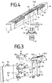
- FIG. 3 shows structural details of the design and arrangement of the shaving heads SK1, SK2 and SK3 according to FIGS and 2 controlling parallelogram joint P is shown.
- Fig. 3 shows a side part S of a frame 14.
- two bolts 17a, 18 are provided which form the pivot bearings 12 and 13 with the bores 19, 20 of the transverse joints 3, 4.
- two bolts 21, 22 are provided, which together with the bores 23, 24 of the rods 10 and 11 form the pivot bearings 7 and 8.
- each further bore 29, 30 is provided which, together with the bolts 30a, 31 provided on the lever 17, form the pivot bearings 15 and 16.
- the upper knives 1 and 2 for example made of shaving foils, of the shaving heads SK1 and SK2 which can be moved relative to one another by means of the rods 10, 11.
- a fastening element 32 is provided on the lever 17, to which the shaving head SK3 designed as a long-hair cutter is fastened - see FIG. 4.
- FIG. 4 shows an embodiment of a pivotable shaving head SK3 with a coupling element 34 which effects the pivoting movement and the drive movement on its lower knife 33.
- the upper knife 36 which is provided with a plurality of slits 35, is fastened at the ends on a carrier element 37, 38.
- the carrier elements 37, 38 serve to fasten the shaving head SK3 to the fastening elements 32 of the levers 17 of the parallelogram joints P provided at the front ends of the shaving heads SK1 and SK2 - see, for example, FIG. 7.
- the upper knife 36 is U-shaped, the one that comes into contact with the skin Is formed flat on the outside, by means of the webs 39 formed by the slots 35, the hair to be cut into the cutting area formed by the upper knife 36 and the lower knife 33 particularly effectively in order to be cut there.
- the lower knife 33 is coupled to the coupling element 34, on which a drive transmission element 40 which is oriented transversely to the direction of vibration of the lower knife 33 is formed.
- a groove 41 is formed in the drive transmission element 40, into which a drive element 43 acted upon by a spring 42 engages.
- the spring 42 and the drive element 43 are arranged in a housing 44 which is directly or indirectly coupled to a drive (not shown) provided in the housing 45 - see FIG. 7 or FIG. 8 - of the dry shaving apparatus.
- the coupling element 34 with the lower knife 33 is held in a resilient contact on the inside of the upper knife 36 via the drive element 43 engaging in the groove 41.
- the arc shape of the inner wall 46 of the groove 41 corresponds to the arc shape of the swivel arc of the shaving head SK3.
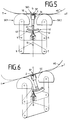
- FIGS. 5, 6 and 7 show a further embodiment of the dry shaving apparatus with a shaving head SK3 which is pivotably mounted about the axis Z and is designed as a long-hair cutter.
- the shaving heads SK1 and SK2 which are designed as short hair cutters, are each coupled at the end to a parallelogram joint P - only one of which is shown schematically.
- the design of the shaving head SK3 arranged between these two shaving heads SK1 and SK2 corresponds to the embodiment according to FIG. 4.
- the lower knives 59, 60 assigned to the upper knives 1 and 2 of the shaving heads SK1, SK2 are spring-mounted on the respective drive pins 61, 62.
- the spring-mounted drive element 43 automatically engages with the groove 41 of the transmission element 40 during the placement process of the completed frame 14 - see FIGS. 4, 5 or 6.
- the outside of the flat upper knife 36 of the The shaving head SK3 has the tangent T. Accordingly, the axis Z, about which the shaving head SK3 is pivotally mounted, lies slightly below the tangent T on the straight line G, that is to say below the intersection point SP of the straight line G with the tangent T. It has been shown that a displacement of the Z axis can be carried out without any appreciable impairment of the pivoting movement of the shaving head SK3 at a certain distance from the intersection point SP shown and described in FIGS. 1 and 2.
- the limits of the permissible distance of the axis Z to the intersection SP can be due to the numerous influencing variables, such as, for example, the outer contour of the shaving head SK3, the friction of its upper knife 36 on the skin, the skin-walking effect of the skin, the distance between the shaving heads SK1 to SK2 and the like, for the respective one Embodiment can be determined by practical tests.
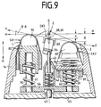
- FIG. 8 shows an exploded view of a further embodiment of a pivotably mounted shaving head SK3.
- a shaving head frame 49 is removably attached.
- a drive element 63 coupled to the drive of the dry shaving apparatus transmits the drive movement via a coupling element 64, which can be coupled to this, via three spring-mounted drive elements 61, 43 and 62 to the lower cutters 59, 33 and 60 of the three shaving heads SK1, SK2 and SK3 via the lower cutters 59 , 33 and 60 provided coupling elements 80, 34 and 81.
- Each of the upper knives 1 and 2 of the shaving heads SK1 and SK2 designed as short hair cutters is movably mounted in the frame 14 which can be coupled to the shaving head frame 49 such that a relative movement of the two shaving heads SK1 and SK2 to one another is ensured.
- An embodiment of such a movable The arrangement of the upper knives 1 and 2 in a frame 14 which can be coupled to a shaving head frame 49 is known, for example, from the document JP-4-132 581 A mentioned in the introduction to the description, which is expressly incorporated by reference here.
- each of the upper knives 1, 2 is resiliently mounted in a frame 14, so that when different external forces are exerted on the upper knives 1, 2, each of the upper knives 1, 2, relative to the other upper knife 1, 2, performs a relative movement.
- This distance X the size of which depends on the force acting on the respective upper knife 1, 2, also arises when both upper knives 1, 2 are evenly subjected to external forces and against the pressure of the springs provided in the frame 14 can be moved in the direction of the shaver housing 45.
- This relative movement of the upper knife 1, 2 also acts against the pressure of the springs, by means of which the respective lower knife 33, 59, 60 are held in contact with the respective upper knife 36, 1, 2.
- These springs are provided between the coupling element transmitting the drive movement and the respective lower knife 33, 59, 60.
- the springs assigned to the lower knives 59, 33, 60 are provided in the coupling element 64 and act on the drive elements 61, 43, 62 or the coupling elements 80, 34, 81.
- the storage of the shaving head SK3 by means of the bearing bolts 47, 48 in the two recesses 68, 69 ensures, on the one hand, the pivoting movement of the shaving head SK3 and a movement of the shaving head SK3 into the frame 14 in the direction of the housing 45.
- the means that shaving heads SK1, SK2, SK3 located in the starting position - as shown in FIGS. 8 and 9 - find a corresponding movement of the shaving heads SK1, SK2 and SK3 from the outside when acting on the outer knives 1, 2, 36 common horizontal straight line H by a distance X, to this horizontal straight line H and thus a displacement of the axis Z of the pivotable shaving head SK3 instead.
- FIG. 9 only one movement variant of three shaving heads SK1, SK2 and SK3 which can be moved independently of one another, for example, is shown schematically, for example.
- the shaving heads SK1 and SK2 are on a common coupling element 64 each against the pressure of one on the upper knife 1, 2 and one on its lower knife 59, 60 acting spring 90, 91 mounted independently of one another so as to be movable.
- the shaving head SK3 arranged between the shaving heads SK1 and SK2 can be moved in the recesses 68, 69 parallel to the direction of the ridges R and can be moved relative to the shaving heads SK1 and SK2 against the pressure of the spring 42 and can be pivoted about the axis Z.
- the shaving head SK2 and the shaving head SK3 move by a corresponding distance X in the direction of the arrow R.
- This movement results in a corresponding displacement of the axis Z within of the recesses 68, 69 and a swiveling movement of the shaving head SK3, the outer contour / upper knife of which automatically adapts to the swiveling angle, which is determined by the angle B which the tangent T or shear plane SE to the outer contour of the two shaving heads SK1 and SK2 to the horizontal line H.
- the three shaving heads SK1, SK2 and SK3 are shifted accordingly by a corresponding distance X from the starting position of the horizontal straight line H in the direction of the arrow R, due to the pivotable mounting of the shaving head SK3 in the recesses 68, 69 the shaving head SK3 assumes a pivoting angle which corresponds to the respective angle B of the tangent T or shear plane SE placed on the outer contour of the two shaving heads SK1 and SK2.
- An additional advantage of the embodiment according to FIGS. 8 and 9 is that the shaving head SK3, which can be moved in the direction of the arrow R against the pressure of a spring and pivotable about the axis Z, can also perform a relative movement with respect to the adjacent shaving heads SK1 and SK2, in particular a Can assume pivot position slightly below the pivot position of the shear plane SE. This favors the constant contact of the three shaving heads SK1, SK2 and SK3 on the skin to be shaved, in particular a continuous adaptation to the constantly changing course of the skin contour to be shaved.
Landscapes
- Life Sciences & Earth Sciences (AREA)
- Forests & Forestry (AREA)
- Engineering & Computer Science (AREA)
- Mechanical Engineering (AREA)
- Dry Shavers And Clippers (AREA)
- Brushes (AREA)
Abstract
Description
Die Erfindung bezieht sich auf einen Trockenrasierapparat mit einem im Gehäuse vorgesehenen Antrieb, wenigstens zwei in Längsrichtung im wesentlichen parallel zueinander verlaufenden, aus jeweils einem Obermesser und einem Untermesser bestehenden Scherköpfen, die relativ und im wesentlichen parallel zueinander bewegbar sind.The invention relates to a dry shaving apparatus with a drive provided in the housing, at least two shaving heads running in the longitudinal direction essentially parallel to one another, each consisting of an upper knife and a lower knife, which can be moved relatively and essentially parallel to one another.
Ein Trockenrasierapparat der eingangs genannten Art ist aus der US-A-4,797,997 bekannt. Die beiden Obermesser der parallel zueinander verlaufenden Scherköpfe sind jeweils endseitig mit einem Parallelogrammgelenk gekoppelt, dessen Quergelenke an Seitenteilen eines gemeinsamen Rahmens schwenkbar angelenkt sind, um eine parallel verlaufende Relativbewegung der beiden Scherköpfe zu bewirken. Die den Obermessern zugeordneten Untermesser sind mit einem Kupplungselement schwenkbar gekoppelt und werden von jeweils einer Feder gegen das jeweilige Obermesser gedrückt. Das Kupplungselement ist mit dem Antrieb des Rasierapparates gekoppelt zwecks Übertragung einer Oszillationsbewegung auf die beiden Untermesser.A dry shaver of the type mentioned is known from US-A-4,797,997. The two upper knives of the shaving heads running parallel to one another are each coupled at the end to a parallelogram joint, the transverse joints of which are pivotably articulated on side parts of a common frame in order to bring about a parallel relative movement of the two shaving heads. The lower knives assigned to the upper knives are pivotally coupled to a coupling element and are each pressed against the respective upper knife by a spring. The coupling element is coupled to the drive of the razor for the purpose of transmitting an oscillating movement to the two lower knives.
Ein Trockenrasierapparat der eingangs genannten Art ist weiterhin aus der JP-4-132 581 A bekannt. Die beiden Obermesser der parallel zueinander verlaufenden Scherköpfe sind, jedes für sich, in einem gemeinsamen Wechselrahmen federnd gelagert, derart, daß bei Ausübung von außen auf die Obermesser unterschiedlich einwirkenden Kräfte jedes der Obermesser gegenüber dem jeweils anderen Obermesser eine entsprechende Relativbewegung ausführt. Die beiden Untermesser der Scherköpfe sind jeweils auf einem mit dem Antrieb des Rasierapparates gekoppelten Kupplungselement federnd angeordnet, wobei die hier vorgesehenen Federn zum einen die Untermesser gegen die Obermesser drücken und zum anderen die Relativbewegung der Obermesser ermöglichen.A dry shaver of the type mentioned is also known from JP-4-132 581 A. The two upper knives of the shaving heads running parallel to each other are each resiliently mounted in a common interchangeable frame, such that when exerted on the upper knives differently acting forces each of the upper knives executes a corresponding relative movement with respect to the other upper knife. The two The lower cutters of the shaving heads are each resiliently arranged on a coupling element coupled to the drive of the shaving apparatus, the springs provided here pressing the lower cutters against the upper cutters on the one hand and enabling the relative movement of the upper cutters on the other hand.
Aus der DE-OS 15 53 659 ist ein Trockenrasierapparat mit drei parallel zueinander angeordneten Scherköpfen bekannt. Der als Langhaarschneider ausgebildete, scharfkantige Schneidzähne aufweisende Scherkopf ist zwischen den beiden äußeren, als Kurzhaarschneider ausgebildeten Scherköpfen ausfahrbar angeordnet, um ein Konturenschneiden von Haaren zu ermöglichen.From DE-OS 15 53 659 a dry shaver with three parallel shaving heads is known. The shaving head, which is designed as a long hair cutter and has sharp-edged cutting teeth, is extendable between the two outer shaving heads, which are designed as short hair cutter, in order to enable contour cutting of hair.
Der Erfindung liegt die Aufgabe zugrunde, das Schneidsystem eines Trockenrasierapparates der eingangs genannten Art zu verbessern.The invention has for its object to improve the cutting system of a dry shaver of the type mentioned.
Nach der Erfindung wird diese Aufgabe dadurch gelöst, daß zwischen den beiden Scherköpfen ein weiterer Scherkopf um eine parallel zu den beiden Scherköpfen verlaufende Achse Z schwenkbar gelagert angeordnet ist.According to the invention, this object is achieved in that a further shaving head is arranged pivotably between the two shaving heads about an axis Z running parallel to the two shaving heads.
Die Lösung nach der Erfindung weist mehrere Vorteile auf. Die Lösung ermöglicht die Anordnung eines weiteren Scherkopfes zwischen zwei relativ und parallel zueinander bewegbaren Scherköpfen und gewährleistet mittels der schwenkbaren Lagerung des zwischen den relativ zueinander bewegbaren Scherköpfen vorgesehenen Scherkopfes eine Anpassung von dessen Schneidbereich an die sogenannte Schneidebene, die durch die jeweilige Winkellage einer an die äußere Kontur der relativ zueinander bewegbaren Scherköpfe gelegten Tangente definiert ist. Ein wesentlicher Vorteil nach der Erfindung besteht unter anderem darin, daß der mit den beiden relativ zueinander bewegbaren Scherköpfen wirksam werdende Schneidbereich des schwenkbar gelagerten Scherkopfes, gegenüber diese durch entsprechende Ausgestaltung eine andere Schneidfunktion ausüben kann, z.B. als Langhaarschneider zum Schneiden von langen, an der Haut anliegenden Haaren, ausgebildet sein kann, wodurch gleichzeitig ein Schnitt von langen Haaren und über die relativ zueinander bewegbaren Scherköpfen von kurzen Haaren gewährleistet ist.The solution according to the invention has several advantages. The solution enables the arrangement of a further shaving head between two shaving heads that can be moved relatively and parallel to one another and, by means of the pivotable mounting of the shaving head provided between the shaving heads that can be moved relative to one another, ensures an adaptation of its cutting area to the so-called cutting plane, which, due to the respective angular position, adjusts one to the outside Contour of the shear heads movable relative to each other is defined tangent. An important advantage according to the invention is, inter alia, that the cutting area which becomes effective with the two shaving heads which can be moved relative to one another of the pivotably mounted shaving head, compared to which, by appropriate design, can perform a different cutting function, for example as a long-hair cutter for cutting long hair lying against the skin, thereby simultaneously cutting long hair and short shaving heads that can be moved relative to one another Hair is guaranteed.
Eine bevorzugte Ausführungsform der Erfindung zeichnet sich dadurch aus, daß die Achse Z durch den Schnittpunkt SP zweier Geraden T und G verläuft, wobei T die gemeinsame Tangente an die äußere Kontur der beiden äußeren Scherköpfe SK1 und SK2 ist und G eine diese Tangente T1 in der Mitte des Abstandes A rechtwinklig schneidende Gerade ist, und A der Abstand der Tangentialpunkte TP1, TP2 der Tangente T an die äußere Kontur der beiden äußeren Scherköpfe SK1 und SK2 ist.A preferred embodiment of the invention is characterized in that the axis Z runs through the intersection SP of two straight lines T and G, where T is the common tangent to the outer contour of the two outer shaving heads SK1 and SK2 and G is this tangent T1 in the The middle of the distance A is a straight line intersecting, and A is the distance of the tangential points TP1, TP2 of the tangent T to the outer contour of the two outer shaving heads SK1 and SK2.
In weiterer Ausgestaltung der Erfindung ist vorgesehen, daß die Achse Z in etwa durch den Schnittpunkt SP zweier Gerade T und G verläuft, wobei T die gemeinsame Tangente an die äußere Kontur der beiden äußeren Scherköpfe SK1, SK2 ist und G eine diese Tangente T1 in der Mitte des Abstandes A rechtwinklig schneidende Gerade ist, und A der Abstand der Tangentialpunkte TP1, TP2 der Tangente T an die äußere Kontur der beiden äußeren Scherköpfe SK1, SK2 ist.In a further embodiment of the invention it is provided that the axis Z runs approximately through the intersection SP of two straight lines T and G, where T is the common tangent to the outer contour of the two outer shaving heads SK1, SK2 and G is this tangent T1 in the The middle of the distance A is a straight line intersecting, and A is the distance of the tangential points TP1, TP2 of the tangent T to the outer contour of the two outer shaving heads SK1, SK2.
Nach einer vorteilhaften Ausführungsform der Erfindung ist vorgesehen, daß bei Ausübung einer von außen auf relativ zueinander bewegbar angeordneten Scherköpfe wirkenden Kraft, die durch die Tangente T gebildete Scherebene SE sowie der zwischen diesen angeordnete Scherkopf um die Achse Z schwenkbar sind.According to an advantageous embodiment of the invention, it is provided that when a force is exerted on the outside of the shaving heads which are arranged to be movable relative to one another, the shear plane SE formed by the tangent T and the shaving head arranged between them can be pivoted about the axis Z.
Ein sehr wesentlicher Vorteil der Erfindung besteht darin, daß diese auf eine sehr einfache Weise eine Anpassung an unterschiedlich gestaltete Bewegungssysteme von zwei relativ zueinander bewegbaren Scherköpfen ermöglicht. Eine einfache und kostengünstige Ausführungsform der Erfindung zeichnet sich dadurch aus, daß die relative Bewegung der beiden äußeren Scherköpfe mittels eines Parallelogrammgelenkes steuerbar ist, an dem wenigstens ein weiterer Hebel zur Steuerung der Schwenkbewegung des mittleren Scherkopfes angelenkt ist. Vorzugsweise ist der mittlere Scherkopf auf dem Hebel angeordnet.A very important advantage of the invention is that it enables adaptation to differently designed movement systems of two shaving heads which can be moved relative to one another in a very simple manner. A simple and inexpensive embodiment of the invention is characterized in that the relative movement of the two outer shaving heads can be controlled by means of a parallelogram joint to which at least one further lever for controlling the pivoting movement of the middle shaving head is articulated. The middle shaving head is preferably arranged on the lever.
In weiterer Ausgestaltung der Erfindung ist der um die Achse Z schwenkbar gelagerte Scherkopf mit der Achse Z gegenüber wenigstens einem der beiden äußeren Scherköpfe relativ bewegbar angeordnet. Diese Ausführungsform der Erfindung gewährleistet eine optimale Anpassung des schwenkbar gelagerten Scherkopfes an relativ zueinander bewegbare Scherköpfe, die unabhängig voneinander relativ zueinander bewegbar angeordnet sind.In a further embodiment of the invention, the shaving head which is pivotably mounted about the axis Z is arranged so as to be relatively movable with the axis Z relative to at least one of the two outer shaving heads. This embodiment of the invention ensures an optimal adaptation of the pivotably mounted shaving head to shaving heads which can be moved relative to one another and which are arranged to be movable relative to one another independently of one another.
In weiterer Ausgestaltung der letztgenannten Ausführungsform ist vorgesehen, daß die Lage der Achse Z des schwenkbar gelagerten Scherkopfes durch Ausübung einer von außen auf den Scherkopf wirkenden Kraft in bezug auf die an die äußere Kontur der beiden äußeren Scherköpfe gelegte Tangente mittels der relativ bewegbaren Anordnung veränderbar ist.In a further embodiment of the last-mentioned embodiment it is provided that the position of the axis Z of the pivotably mounted shaving head can be changed by means of the relatively movable arrangement by exerting an external force acting on the shaving head with respect to the tangent to the outer contour of the two outer shaving heads .
In weiterer Ausgestaltung der Ausführungsformen nach den beiden zuvor genannten Ausführungsformen ist vorgesehen, daß bei Ausübung einer von außen auf wenigstens einer der Scherköpfe wirkenden Kraft der Schwenkwinkel A des schwenkbar gelagerten Scherkopfes im wesentlichen dem jeweiligen Winkel A entspricht, den die an die äußere Kontur der beiden äußeren Scherköpfe gelegte Tangente T bzw. Scherebene SE zu einer horizontalen Geraden H einnimmt.In a further embodiment of the embodiments according to the two aforementioned embodiments, it is provided that when exerting a force acting externally on at least one of the shaving heads, the pivoting angle A of the pivotably mounted shaving head corresponds essentially to the respective angle A which the tangent T or shear plane SE placed on the outer contour of the two outer shaving heads assumes to a horizontal straight line H.
In weiterer Ausgestaltung der Erfindung ist der um die Achse Z schwenkbar gelagerte Scherkopf als Langhaarschneider ausgebildet.In a further embodiment of the invention, the shaving head, which is pivotably mounted about the axis Z, is designed as a long-hair cutter.
Nach dem eingangs zitierten Stand der Technik sind die beiden relativ zueinander bewegbaren Scherköpfe bekanntlich als Kurzhaarschneider ausgebildet. Die Ausbildung des zwischen diesen als Langhaarschneider ausgebildeten schwenkbar gelagerten Scherkopfes gewährleistet automatisch eine Kombinationsrasur, das heißt, ein gleichzeitiges Schneiden von kurzen und langen Haaren.According to the prior art cited at the outset, the two shaving heads which are movable relative to one another are known to be designed as short hair cutters. The formation of the pivotably mounted shaving head, which is designed as a long hair cutter, automatically ensures a combination shave, that is to say simultaneous cutting of short and long hair.
Nach einer bevorzugten Ausführungsform der Erfindung ist das Obermesser des Langhaarschneiders im wesentlichen U-förmig ausgebildet. Durch die schwenkbare Anordnung des Langhaarschneiders ist gewährleistet, daß die ebenflächig ausgebildete Außenseite des Obermessers zur Anlage an die Haut gelangt und hautschonend über die Hautoberfläche bewegt werden kann, um lange Haare in den scheraktiven Schneidbereich von Obermesser und Untermesser einzufädeln. Ein wesentlicher Vorteil der U-förmigen Ausgestaltung des Obermessers des Langhaarschneiders besteht darin, daß dieser zusammen mit den als Kurzhaarschneider ausgebildeten Scherköpfen in beliebiger Richtung hautschonend über die Hautoberfläche bewegt werden kann und in allen Bewegungsrichtungen scheraktiv wirksam wird.According to a preferred embodiment of the invention, the upper knife of the long hair trimmer is essentially U-shaped. The pivotable arrangement of the long hair trimmer ensures that the flat outer surface of the upper knife comes into contact with the skin and can be moved over the surface of the skin in order to thread long hair into the shear-active cutting area of the upper knife and lower knife. A major advantage of the U-shaped configuration of the upper knife of the long-hair trimmer is that it can be moved over the skin surface in any direction together with the shaving heads designed as short-hair trimmers and is shear-active in all directions of movement.
Nach der Erfindung sind die parallel zu dem schwenkbar gelagerten Scherkopf angeordneten Scherköpfe als Kurzhaarschneider ausgebildet. In weiterer Ausgestaltung der Erfindung ist der schwenkbar gelagerte Scherkopf mit einem quer zur Längsrichtung der Scherköpfe schwenkbaren Kupplungselement gekoppelt, das mit einem die Oszillationsbewegung bewirkenden Antriebselement gekoppelt ist.According to the invention, the shaving heads arranged parallel to the pivotably mounted shaving head are designed as short hair cutters. In a further embodiment of the invention, the pivotably mounted shaving head is coupled to a coupling element which can be pivoted transversely to the longitudinal direction of the shaving heads and which is coupled to a drive element which effects the oscillating movement.
Nach einer sehr kostengünstigen Ausgestaltung der Erfindung ist vorgesehen, daß ein von dem Antrieb des Trockenrasierapparates angetriebenes Kupplungselement vorgesehen ist, auf dem die als Kurzhaarschneider ausgebildeten Scherköpfe SK1, SK2 relativ zueinander bewegbar angeordnet und ein Antriebselement für den schwenkbar gelagerten Scherkopf SK3 vorgesehen ist. Ein derartiges Kupplungselement ermöglicht einerseits eine einfache Koppelung bzw. Entkoppelung mit dem Antrieb des Trockenrasierapparates und andererseits eine leicht handhabbare Koppelung bzw. Entkoppe-lung mit bzw. ohne den Untermessern der relativ zueinander beweg- baren Scherköpfe.According to a very inexpensive embodiment of the invention, it is provided that a coupling element driven by the drive of the dry shaving apparatus is provided, on which the shaving heads SK1, SK2 designed as short hair cutters are arranged so as to be movable relative to one another and a drive element for the pivotably mounted shaving head SK3 is provided. Such a coupling element on the one hand enables simple coupling or decoupling with the drive of the dry shaving apparatus and, on the other hand, easy-to-handle coupling or decoupling with or without the lower knives of the shaving heads which can be moved relative to one another.
Nach einer weiteren Ausführungsform der Erfindung ist jedem der vorgesehenen Scherköpfe ein Kupplungselement zugeordnet, das mit im Gehäuse vorgesehenen Antrieb gekoppelt ist. Diese Ausführungsform ermöglicht beispielsweise in Verbindung mit einem als Doppelexzenter ausgebildeten Antrieb eine gegenläufige Oszillationsbewegung von einem der Untermesser zu wenigstens einem der anderen Untermesser der vorgesehenen Scherköpfe.According to a further embodiment of the invention, each of the shaving heads provided is assigned a coupling element which is coupled to the drive provided in the housing. This embodiment enables, for example in conjunction with a drive designed as a double eccentric, an opposing oscillating movement from one of the lower knives to at least one of the other lower knives of the shaving heads provided.
Nach einer weiteren Ausführungsform der Erfindung sind die als Kurzhaarschneider ausgebildeten Scherköpfe auf einem gemeinsamen, mit einem Antrieb gekoppelten Kupplungselement relativ zueinander bewegbar angeordnet. Diese Ausführungsform ermöglicht eine gegenläufige Oszillationsbewegung des Untermessers des schwenkbar gelagerten Scherkopfes in bezug auf die Untermesser der als Kurzhaarschneider ausgebildeten relativ zueinander bewegbaren Scherköpfe.According to a further embodiment of the invention, the shaving heads designed as short hair cutters are arranged so as to be movable relative to one another on a common coupling element coupled to a drive. This embodiment enables an opposing oscillation movement of the lower knife of the pivotably mounted shaving head with respect to the lower knife of the shaving heads, which are designed as short hair cutters and can be moved relative to one another.
Weitere bevorzugte Ausführungsformen der Erfindung ergeben sich aus den Unteransprüchen 7, 8, 19 und 20, die insbesondere einfache und preiswert herstellbare Maßnahmen zur Anordnung und Lagerung eines schwenkbaren Scherkopfes aufzeigen.Further preferred embodiments of the invention result from
In der nachfolgenden Beschreibung und den Zeichnungen sind einige Ausführungsbeispiele dargestellt. Es zeigt:
- Fig. 1
- eine schematische Darstellung eines Scherkopfsystems mit einem Parallelogrammgelenk zur Steuerung der Scherköpfe
- Fig. 2
- Stellung der Scherköpfe nach Fig. 1 bei Ausübung einer Kraft auf einen der Scherköpfe
- Fig. 3
- Konstruktive Details einer Scherkopfsteuerung nach Fig. 1 und Fig. 2
- Fig. 4
- Konstruktive Ausgestaltung eines schwenkbar gelagerten Langhaarschneiders mit Antriebselementen
- Fig. 5
- eine schematische Darstellung eines mittels Parallelogrammgelenk gesteuerten Scherkopfsystems und diesem zugeordneten schwenkbar gelagerten Langhaarschneidsystem
- Fig. 6
- Stellung der Scherköpfe nach Fig. 5 bei Ausübung einer Kraft auf einen der Scherköpfe
- Fig. 7
- eine Explosionsdarstellung des oberen Teils eines Rasierapparates mit Hilfsrahmen zur Aufnahme der Scherköpfe und einem Scherkopfrahmen.
- Fig. 8
- eine Explosionsdarstellung des oberen Teils eines Rasierapparates mit einem Scherkopfrahmen und einem Hilfsrahmen mit drei relativ zueinander bewegbaren Scherköpfen
- Fig. 9
- schematische Darstellung der Anordnung der drei relativ zueinander bewegbaren Scherköpfe mit schwenkbarer Lagerung des mittleren Scherkopfes nach Fig. 8
- Fig. 1
- is a schematic representation of a shaving head system with a parallelogram joint for controlling the shaving heads
- Fig. 2
- Position of the shaving heads according to FIG. 1 when a force is exerted on one of the shaving heads
- Fig. 3
- Constructive details of a shaving head control according to FIGS. 1 and 2
- Fig. 4
- Structural design of a pivoted long hair trimmer with drive elements
- Fig. 5
- is a schematic representation of a shaving head system controlled by means of a parallelogram joint and associated with this pivotably mounted long hair cutting system
- Fig. 6
- Position of the shaving heads according to FIG. 5 when a force is exerted on one of the shaving heads
- Fig. 7
- an exploded view of the upper part of a razor with subframe for receiving the shaving heads and a shaving head frame.
- Fig. 8
- an exploded view of the upper part of a razor with a shaving head frame and a sub-frame with three relatively movable shaving heads
- Fig. 9
- 8 shows a schematic representation of the arrangement of the three shaving heads that can be moved relative to one another with pivotable mounting of the middle shaving head according to FIG. 8
Fig. 1 zeigt in schematischer Darstellung zwei in Längsrichtung parallel zueinander verlaufende, als Kurzhaarschneider ausgebildete Scherköpfe SK1, SK2 sowie einen zwischen diesen Scherköpfen SK1 und SK2 angeordneten, als Langhaarschneider ausgebildeten Scherkopf SK3. Die beiden Obermesser 1, 2 der Scherköpfe SK1 und SK2 sind jeweils endseitig mit einem Parallelogrammgelenk P gekoppelt, dessen Quergelenke 3, 4 über Schwenklager 6, 7, 8 und 9 mit zwei parallel zu einer vertikalen Geraden G verlaufenden Stangen 10, 11 schwenkbar gekoppelt und über zwei weitere Schwenklager 12, 13 an den Seitenteilen S eines gemeinsamen Rahmens 14 - siehe Fig. 3 - schwenkbar angelenkt sind, um eine Relativbewegung der beiden an den oberen Enden der Stangen 10, 11 mittels Schwenklager 15, 16 schwenkbar angelenkten Scherköpfe SK1, SK2 zu bewirken bzw. zu steuern. Der Scherkopf SK3 ist mittels eines Hebels 17 an den beiden Schwenklagern 15, 16 schwenkbar angelenkt.1 shows, in a schematic representation, two shaving heads SK1, SK2 running parallel to one another in the longitudinal direction and designed as short hair cutters, and a shaving head SK3 arranged between these shaving heads SK1 and SK2 and designed as a long hair cutter. The two
Die die beiden bogenförmig ausgebildeten Scherköpfe SK1 und SK2 verbindende Tangentialebene ist eine gedachte Ebene, die im folgenden als Scherebene SE bezeichnet wird. Die gemeinsame Tangente T an die Bogenform der Scherköpfe SK1 und SK2, bestimmt mit den Tangentialpunkten TP1 und TP2 einerseits den Übergang von der Scherebene SE in die anschließenden Bogenformen und andererseits durch den Abstand A, den die Tangentialpunkte TP1 und TP2 zueinander haben, die Breite der Scherebene SE, deren Erstreckung in Längsrichtung der Scherköpfe SK1, SK2 von deren Länge abhängig ist. Eine Gerade G schneidet die Tangente T rechtwinklig und zwar in der Mitte des Abstandes A. Durch den aus diesem Schnitt resultierenden Schnittpunkt SP verläuft die Schwenkachse Z parallel zu den sich in Längsrichtung erstreckenden Scherköpfen SK1, SK2 und SK3. Der mit dem Parallelogrammgelenk P schwenkbar gekoppelte Scherkopf SK3 tangiert mit seiner äußeren Kontur, die ebenflächig gestaltet ist, die Tangente T bzw. Scherebene SE und vollzieht mit der Tangente T bzw. Scherebene SE eine Schwenkbewegung um die Achse Z, wie dies beispielsweise in Fig. 2 dargestellt ist. Die beiden Stangen 10, 11 bewegen sich bei Ausübung einer von außen auf die Scherköpfe SK1 und SK2 wirkenden Kraft relativ und parallel zueinander sowie parallel zu der Geraden G, mittels der der Schnittpunkt SP für die Achse Z bestimmt ist und auf der die Schwenklager 12 und 13 der Quergelenke 3 und 4 vorgesehen sind. Bei Ausübung einer von außen auf wenigstens einer der Scherköpfe SK1 oder SK2 wirkenden Kraft entspricht der Schwenkwinkel des schwenkbar gelagerten Scherkopfes SK3 dem jeweiligenWinkel B, den die an die äußere Kontur der beiden äußeren Scher- köpfe SK1 und SK2 gelegte Tangente T bzw. Scherebene SE zu einer, den Schnittpunkt SP schneidenden, horizontalen Geraden H ein- nimmt. Die horizontale Gerade H ist eine Hilfslinie, mit der die Stellung von relativ zueinander bewegbaren Scherköpfen SK1, SK2 bei Nichteinwirkung von außen auf diese einwirkenden Kräfte definiert ist, das heißt, die unbelastete Ausgangsstellung der Scherköpfe SK1, SK2 kennzeichnet.The tangential plane connecting the two arcuate shaving heads SK1 and SK2 is an imaginary plane, which is referred to below as the shear plane SE. The common tangent T to the arc shape of the shaving heads SK1 and SK2, with the tangential points TP1 and TP2, determines the transition from the one hand Shear plane SE into the subsequent arch shapes and, on the other hand, through the distance A that the tangential points TP1 and TP2 have to one another, the width of the shear plane SE, the extent of which in the longitudinal direction of the shaving heads SK1, SK2 depends on their length. A straight line G intersects the tangent T at right angles and in the middle of the distance A. Because of the intersection SP resulting from this cut, the pivot axis Z runs parallel to the shaving heads SK1, SK2 and SK3 extending in the longitudinal direction. The outer contour of the shaving head SK3, which is pivotally coupled to the parallelogram joint P, tangents the tangent T or shear plane SE and, with the tangent T or shear plane SE, pivots around the axis Z, as shown, for example, in FIG. 2 is shown. The two
In Fig. 3 sind konstruktive Einzelheiten der Ausbildung und Anordnung des die Scherköpfe SK1, SK2 und SK3 nach den Figuren 1 und 2 steuernden Parallelogrammgelenkes P dargestellt. Fig. 3 zeigt ein Seitenteil S eines Rahmens 14. An der Innenseite sind zwei Bolzen 17a, 18 vorgesehen, die mit den Bohrungen 19, 20 der Quergelenke 3, 4 die Schwenklager 12 und 13 bilden. An dem Quergelenk 3 sind zwei Bolzen 21, 22 vorgesehen, die mit den Bohrun- gen 23, 24 der Stangen 10 und 11 die Schwenklager 7 und 8 bilden. Die am Quergelenk 4 vorgesehenen Bolzen 25, 26 bilden mit den in den Stangen 10 und 11 vorgesehenen Bohrungen 27, 28 die Schwenk- lager 6 und 9. An den den Bohrungen 23, 24 gegenüberliegenden En- den der Stangen 10 und 11 ist jeweils eine weitere Bohrung 29, 30 vorgesehen, die mit den am Hebel 17 vorgesehenen Bolzen 30a, 31 die Schwenklager 15 und 16 bilden. An den oberen Enden der Stan- gen 10 und 11 sind die beispielsweise aus Scherfolien bestehenden Obermesser 1 und 2 der mittels der Stangen 10, 11 relativ zuein- ander bewegbaren Scherköpfe SK1 und SK2 vorgesehen.3 shows structural details of the design and arrangement of the shaving heads SK1, SK2 and SK3 according to FIGS and 2 controlling parallelogram joint P is shown. Fig. 3 shows a side part S of a
In der Mitte zwischen den beiden Bolzen 30a, 31 ist am Hebel 17 ein Befestigungselement 32 vorgesehen, an dem der als Langhaarschneider ausgebildete Scherkopf SK3 - siehe Fig. 4 - befestigt wird.In the middle between the two
In Fig. 4 ist eine Ausführungsform eines schwenkbar lagerbaren Scherkopfes SK3 mit einem die Schwenkbewegung und die Antriebsbewegung auf dessen Untermesser 33 bewirkenden Kupplungselementes 34 dargestellt. Das mit einer Vielzahl von Schlitzen 35 versehene Obermesser 36 ist jeweils endseitig auf einem Trägerelement 37, 38 befestigt. Die Trägerelemente 37, 38 dienen bei der Ausführungsform nach Fig. 3 zur Befestigung des Scherkopfes SK3 an den Befestigungselementen 32 der Hebel 17 der an den stirnseitigen Enden der Scherköpfe SK1 und SK2 jeweils vorgesehenen Parallelogrammgelenke P - siehe z.B. Fig. 7. Das Obermesser 36 ist U-förmig gestaltet, dessen zur Anlage an die Haut gelangende Außenseite ebenflächig ausgebildet ist, um mittels der durch die Schlitze 35 gebildeten Stege 39 die zu schneidenden Haare in den durch das Obermesser 36 und das Untermesser 33 gebildeten Schneidbereich besonders wirksam einzufädeln, um dort geschnitten zu werden. Das Untermesser 33 ist mit dem Kupplungselement 34, an dem ein quer zur Schwingungsrichtung des Untermessers 33 ausgerichtetes Antriebsübertragungselement 40 angeformt ist, gekoppelt. In dem Antriebsübertragungselement 40 ist eine Nut 41 eingeformt, in die ein von einer Feder 42 beaufschlagtes Antriebselement 43 eingreift. Die Feder 42 und das Antriebselement 43 sind in einem Gehäuse 44 angeordnet, das mit- telbar oder unmittelbar mit einem im Gehäuse 45 - siehe Fig. 7 oder Fig. 8 - des Trockenrasierapparates vorgesehenen Antrieb (nicht dargestellt) gekoppelt ist. Mittels der Feder 42 wird über das in die Nut 41 eingreifenden Antriebselement 43 das Kupplungselement 34 mit dem Untermesser 33 in einer federnden Anlage an der Innenseite des Obermessers 36 gehalten. Die Bogenform der Innenwandung 46 der Nut 41 entspricht der Bogenform des Schwenkbogens des Scherkopfes SK3.FIG. 4 shows an embodiment of a pivotable shaving head SK3 with a
In den Figuren 5, 6 und 7 ist eine weitere Ausführungsform des Trockenrasierapparates mit einem um die Achse Z schwenkbar gelagerten, als Langhaarschneider ausgebildeten, Scherkopf SK3 dargestellt. Nach dieser Ausführungsform sind die als Kurzhaarschneider ausgebildeten Scherköpfe SK1 und SK2 jeweils endseitig mit einem Parallelogrammgelenk P - von denen lediglich eines schematisch dargestellt ist - gekoppelt. Der zwischen diesen beiden Scherköpfen SK1 und SK2 angeordnete Scherkopf SK3 entspricht in seiner Ausgestaltung der Ausführungsform nach Fig. 4. Über an den Trägerelementen 37, 38 vorgesehenen Lagerbolzen 47, 48 ist der Scherkopf SK3 - siehe Fig. 7 - in einem auf das Gehäuse 45 aufsetzbaren Rahmen 14 - der von einem Scherkopfrahmen 49 umgeben ist oder auch Bestandteil des Scherkopfrahmens 49 sein kann - schwenkbar gelagert und zwar in den Bohrungen 70 und 71, die in den Seitenplatten 50, 51 des Rahmens 14 vorgesehen sind. Die in den Seitenplatten 50, 51 vorgesehenen Bohrungen 19, 20 dienen zur Aufnahme der Bolzen 17a, 18 und bilden mit diesen die Schwenklager 12, 13 zwecks Steuerung der Relativbewegung der beiden Scherköpfe SK1 und SK2 zueinander. Die in den Figuren 1, 5 und 6 angegebenen Schwenklager 6, 7, 8 und 9 sind in der Ausführungsform nach Fig. 7 als Filmscharniere ausgebildet und bilden mit den Stangen 10 und 11 sowie den daran angeordneten Obermessern 1 und 2 der beiden Scherköpfe SK1 und SK2 eine Baueinheit, die nach Einsatz der beiden Stangen 10 in die Schlitze 52 und 53 und den beiden Stangen 11 in die Schlitze 54, 55 sowie der Seitenplatten 50, 51 in die Schlitze 56, 57 von dem Rahmen 14 gehalten und getragen werden, zusammen mit dem mittels der Lagerbolzen 47, 48 in den Bohrungen 70, 71 der Seitenplatten 50, 51 schwenkbar angeordneten Scherkopf SK3. Der mit den Scherköpfen SK1, SK2, SK3 komplettierte Rahmen 14 wird auf die Gehäuseoberseite 58 des Gehäuses 45 aufgesetzt und mittels des den Rahmen 14 umgebenden Scherkopfrahmens 49 dort abnehmbar befestigt. Die den Obermessern 1 und 2 der Scherköpfe SK1, SK2 zugeordneten Untermesser 59, 60 sind auf den jeweiligen Antriebsstiften 61, 62 federnd gelagert. Das federnd gelagerte Antriebselement 43 gelangt während des Aufsetzvorganges des komplettierten Rahmens 14 automatisch in Eingriff mit der Nut 41 des Übertragungselementes 40 - siehe Figuren 4, 5 oder 6.FIGS. 5, 6 and 7 show a further embodiment of the dry shaving apparatus with a shaving head SK3 which is pivotably mounted about the axis Z and is designed as a long-hair cutter. According to this embodiment, the shaving heads SK1 and SK2, which are designed as short hair cutters, are each coupled at the end to a parallelogram joint P - only one of which is shown schematically. The design of the shaving head SK3 arranged between these two shaving heads SK1 and SK2 corresponds to the embodiment according to FIG. 4. Via bearing
Bei der Ausführungsform nach den Figuren 5, 6 und 7 tangiert die Außenseite des ebenflächig ausgebildeten Obermessers 36 des Scherkopfes SK3 die Tangente T. Demzufolge liegt die Achse Z, um die der Scherkopf SK3 schwenkbar gelagert ist, geringfügig unterhalb der Tangente T auf der Geraden G, das heißt, unterhalb des Schnittpunktes SP der Geraden G mit der Tangente T. Es hat sich gezeigt, daß eine Verlagerung der Achse Z ohne nennenswerte Beeinträchtigung der Schwenkbewegung des Scherkopfes SK3 in einem gewissen Abstand zu dem in den Figuren 1 und 2 dargestellten und beschriebenen Schnittpunkt SP vorgenommen werden kann. Die Grenzen des zulässigen Abstandes der Achse Z zum Schnittpunkt SP können aufgrund der zahlreichen Einflußgrößen, wie z.B. äußere Kontur des Scherkopfes SK3, Reibung dessen Obermessers 36 an der Haut, Hautwalkeffekt der Haut, Abstand der Scherköpfe SK1 bis SK2 zueinander und dergleichen, für die jeweilige Ausführungsform durch praktische Versuche ermittelt werden.In the embodiment according to FIGS. 5, 6 and 7, the outside of the flat
Fig. 8 zeigt in einer Explosionsdarstellung eine weitere Ausführungsform eines schwenkbar gelagerten Scherkopfes SK3. Auf der Gehäuseoberseite 58 des Gehäuses 45 ist ein Scherkopfrahmen 49 abnehmbar befestigt. Ein mit dem Antrieb des Trockenrasierapparates gekoppeltes Antriebselement 63 überträgt die Antriebsbewegung über ein mit diesem koppelbaren Kupplungselement 64 über drei federnd gelagerte Antriebselemente 61, 43 und 62 auf die Untermesser 59, 33 und 60 der drei Scherköpfe SK1, SK2 und SK3 über an den Untermessern 59, 33 und 60 vorgesehene Kupplungselemente 80, 34 und 81.8 shows an exploded view of a further embodiment of a pivotably mounted shaving head SK3. On the
Jedes der Obermesser 1 und 2 der als Kurzhaarschneider ausgebildeten Scherköpfe SK1 und SK2 ist in dem mit dem Scherkopfrahmen 49 koppelbaren Rahmen 14 derart bewegbar gelagert, daß eine Relativbewegung der beiden Scherköpfe SK1 und SK2 zueinander gewährleistet ist. Eine Ausführungsform einer derartigen bewegbaren Anordnung der Obermesser 1 und 2 in einen mit einem Scherkopfrahmen 49 koppelbaren Rahmen 14 ist beispielsweise aus der in der Beschreibungseinleitung genannten Druckschrift JP-4-132 581 A bekannt, die hier ausdrücklich in Bezug genommen wird. Gemäß Fig. 5 dieser bekannten Druckschrift ist jedes der Obermesser 1, 2 in einem Rahmen 14 federnd gelagert, so daß bei Ausübung von außen auf die Obermesser 1, 2 einwirkenden unterschiedlichen Kräften jedes der Obermesser 1, 2, gegenüber dem jeweils anderen Obermesser 1, 2, eine Relativbewegung ausführt. Die Obermesser 1, 2 nehmen dabei eine relative Stellung zueinander ein. Da jedes der beiden Obermesser 1, 2 federnd gelagert ist, stellt sich unter Berücksichtigung der auf beide Obermesser 1, 2 jeweils einwirkenden Kraft auch ein Abstand X zu einer an im unbelasteten Zustand, das heißt, in Ausgangsstellung befindlichen Obermesser 1, 2 an die Obermesser gelegten horizontalen Geraden H = Tangente ein. Dieser Abstand X, dessen Größe von der auf das jeweilige Obermesser 1, 2 einwirkenden Kraft abhängig ist, stellt sich auch ein, wenn beide Obermesser 1, 2 gleichmäßig von außen mit Kräften beaufschlagt und gegen den Druck der jeweils vorgesehenen Federn in den Rahmen 14 hinein in Richtung des Gehäuses 45 des Rasierapparates bewegt werden. Diese relative Bewegung der Obermesser 1, 2 wirkt auch gegen den Druck der Federn, mittels denen die jeweiligen Untermesser 33, 59, 60 in Anlage an dem jeweiligen Obermesser 36, 1, 2 gehalten werden. Diese Federn sind zwischen dem die Antriebsbewegung übertragenden Kupplungselement und dem jeweiligen Untermesser 33, 59, 60 vorgesehen.Each of the
Bei dem Ausführungsbeispiel nach den Figuren 8 und 9 sind die den Untermesser 59, 33, 60 jeweils zugeordneten Federn in dem Kupplungselement 64 vorgesehen und beaufschlagen die Antriebselemente 61, 43, 62, oder die Kupplungselemente 80, 34, 81.In the exemplary embodiment according to FIGS. 8 and 9, the springs assigned to the
In den beiden Innenwänden 66, 67 der Stirnseiten des Rahmens 14 ist jeweils eine in vertikaler Richtung verlaufende längliche Ausnehmung 68, 69 zur Aufnahme der Lagerbolzen 47, 48 des zwischen den beiden relativ zueinander bewegbaren Scherköpfe SK1 und SK2 angeordneten Scherkopfes SK3 vorgesehen.In the two
Die Lagerung des Scherkopfes SK3 mittels der Lagerbolzen 47, 48 in den beiden Ausnehmungen 68, 69 gewährleistet einerseits die Schwenkbewegung des Scherkopfes SK3 sowie eine Bewegung des Scherkopfes SK3 in den Rahmen 14 hinein in Richtung des Gehäuses 45. Ausgehend von drei im unbelasteten Zustand, das heißt, in Ausgangsstellung befindlichen Scherköpfen SK1, SK2, SK3 - wie dies in den Figuren 8 und 9 dargestellt ist - findet bei Einwirkung von außen auf die Obermesser 1, 2, 36 einwirkenden Kräften eine entsprechende Bewegung der Scherköpfe SK1, SK2 und SK3 von der gemeinsamen horizontalen Geraden H um einen Abstand X, zu dieser horizontalen Geraden H und somit eine Verlagerung der Achse Z des schwenkbaren Scherkopfes SK3 statt. Aus dieser Verlagerung der Achse Z und der Schwenkbarkeit des Scherkopfes SK3 um diese Achse Z ergibt sich automatisch eine Anpassung des Schwenkwinkels des Scherkopfes SK3 an den jeweiligen Schwenkwinkel B der Tangente T bzw. Scherebene SE, da die Anordnung der Ausnehmungen 68, 69 im Rahmen 14 derart getroffen ist, daß - wie aus Fig. 9 ersichtlich - eine Verlagerung der um die Achse Z schwenkbaren Tangente T bzw. Scherebene SE in Richtung Gehäuse 45 gegen den Druck der Feder 42 auf der Geraden G erfolgt.The storage of the shaving head SK3 by means of the bearing
In Fig. 9 ist lediglich eine Bewegungsvariante von drei unabhängig voneinander relativ zueinander bewegbaren Scherköpfen SK1, SK2 und SK3 beispielsweise schematisch dargestellt. Die Scherköpfe SK1 und SK2 sind auf einem gemeinsamen Kupplungselement 64 jeweils gegen den Druck einer auf deren Obermesser 1, 2 sowie einer auf deren Untermesser 59, 60 einwirkenden Feder 90, 91 unabhängig voneinander relativ zueinander bewegbar gelagert. Der zwischen den Scherköpfen SK1 und SK2 angeordnete Scherkopf SK3 ist in den Ausnehmungen 68, 69 in Pfellrichtung R parallel und relativ zu den Scherköpfen SK1 und SK2 gegen den Druck der Feder 42 bewegbar und um die Achse Z schwenkbar gelagert. Bei Ausübung beispielsweise von nur auf den Scherkopf SK2 und SK3 einwirkenden äußeren Kräften während des Gebrauchs des Trockenrasierap-parates bewegen sich der Scherkopf SK2 und der Scherkopf SK3 um einen entsprechenden Abstand X in Pfeilrichtung R. Aus dieser Bewegung resultiert eine entsprechende Verlagerung der Achse Z innerhalb der Ausnehmungen 68, 69 sowie eine Schwenkbewegung des Scherkopfes SK3, dessen äußere Kontur/Obermesser sich automatisch an den Schwenkwinkel anpasst, der bestimmt ist durch den Winkel B, den die Tangente T bzw. Scherebene SE an die äußere Kontur der beiden Scherköpfe SK1 und SK2 zur horizontalen Geraden H einnimmt.In FIG. 9, only one movement variant of three shaving heads SK1, SK2 and SK3 which can be moved independently of one another, for example, is shown schematically, for example. The shaving heads SK1 and SK2 are on a
Bei gleichzeitiger Ausübung von Kräften auf alle drei Scherköpfe SK1, SK2 und SK3 (nicht dargestellt) findet eine entsprechende Verschiebung der drei Scherköpfe SK1, SK2 und SK3 um einen entsprechenden Abstand X von der Ausgangsstellung der horizontalen Geraden H in Pfeilrichtung R statt, wobei aufgrund der schwenkbaren Lagerung des Scherkopfes SK3 in den Ausnehmungen 68, 69 der Scherkopf SK3 einen Schwenkwinkel einnimmt, der dem jeweiligen Winkel B der an die äußere Kontur der beiden Scherköpfe SK1 und SK2 gelegten Tangente T bzw. Scherebene SE entspricht.When forces are simultaneously exerted on all three shaving heads SK1, SK2 and SK3 (not shown), the three shaving heads SK1, SK2 and SK3 are shifted accordingly by a corresponding distance X from the starting position of the horizontal straight line H in the direction of the arrow R, due to the pivotable mounting of the shaving head SK3 in the
Ein zusätzlicher Vorteil der Ausführungsform nach den Figuren 8 und 9 besteht darin, daß der in Pfeilrichtung R gegen den Druck einer Feder bewegbare und um die Achse Z schwenkbare Scherkopf SK3 in bezug auf die benachbarten Scherköpfe SK1 und SK2 ebenfalls eine Relativbewegung ausführen kann, insbesondere eine Schwenkstellung geringfügig unterhalb der Schwenkstellung der Scherebene SE einnehmen kann. Dies begünstigt die ständige Anlage der drei Scherköpfe SK1, SK2 und SK3 an der zu rasierenden Haut, insbesondere eine kontinuierliche Anpassung an den ständig wechselnden Verlauf der zu rasierenden Hautkontur.An additional advantage of the embodiment according to FIGS. 8 and 9 is that the shaving head SK3, which can be moved in the direction of the arrow R against the pressure of a spring and pivotable about the axis Z, can also perform a relative movement with respect to the adjacent shaving heads SK1 and SK2, in particular a Can assume pivot position slightly below the pivot position of the shear plane SE. This favors the constant contact of the three shaving heads SK1, SK2 and SK3 on the skin to be shaved, in particular a continuous adaptation to the constantly changing course of the skin contour to be shaved.
Claims (20)
Applications Claiming Priority (2)
| Application Number | Priority Date | Filing Date | Title |
|---|---|---|---|
| DE4244164A DE4244164C2 (en) | 1992-12-24 | 1992-12-24 | Dry shaver with a pivoting long hair trimmer |
| DE4244164 | 1992-12-24 |
Publications (2)
| Publication Number | Publication Date |
|---|---|
| EP0603617A1 true EP0603617A1 (en) | 1994-06-29 |
| EP0603617B1 EP0603617B1 (en) | 1997-01-08 |
Family
ID=6476590
Family Applications (1)
| Application Number | Title | Priority Date | Filing Date |
|---|---|---|---|
| EP93119578A Expired - Lifetime EP0603617B1 (en) | 1992-12-24 | 1993-12-04 | Dry shaver with a pivotable long hair cutter |
Country Status (5)
| Country | Link |
|---|---|
| US (1) | US5704126A (en) |
| EP (1) | EP0603617B1 (en) |
| JP (1) | JP3514794B2 (en) |
| AT (1) | ATE147314T1 (en) |
| DE (2) | DE4244164C2 (en) |
Cited By (2)
| Publication number | Priority date | Publication date | Assignee | Title |
|---|---|---|---|---|
| US6223438B1 (en) | 1996-07-05 | 2001-05-01 | Braun Gmbh | Dry shaving apparatus |
| US6308414B1 (en) | 1996-07-05 | 2001-10-30 | Braun Gmbh | Dry shaving apparatus |
Families Citing this family (38)
| Publication number | Priority date | Publication date | Assignee | Title |
|---|---|---|---|---|
| US5611145A (en) * | 1991-12-20 | 1997-03-18 | Wetzel; Matthias | Dry-shaving apparatus |
| JP3699736B2 (en) * | 1995-01-11 | 2005-09-28 | 株式会社泉精器製作所 | Electric razor |
| JP2002052270A (en) * | 2000-08-11 | 2002-02-19 | Izumi Products Co | Rotary electric razor |
| DE10052296C1 (en) * | 2000-10-20 | 2002-04-04 | Braun Gmbh | Electrically-operated hair removal device has pulsed stroboscopic light signal provided by illumination device for illumination of relatively moving working elements |
| JP3979052B2 (en) * | 2001-09-25 | 2007-09-19 | 松下電工株式会社 | Reciprocating electric razor |
| KR100562388B1 (en) * | 2001-11-15 | 2006-03-17 | 마츠시다 덴코 가부시키가이샤 | Dry shaver with a cradle shaving head |
| KR100599921B1 (en) * | 2002-06-17 | 2006-07-12 | 마츠시다 덴코 가부시키가이샤 | Dry shaver with a trimmer |
| US7137205B2 (en) * | 2002-10-01 | 2006-11-21 | The Gillette Company | Linkage mechanism providing a virtual pivot axis for razor apparatus with pivotal head |
| DE60204780T2 (en) | 2002-10-01 | 2006-05-18 | The Gillette Co., Boston | Articulated gear with virtual swivel axis for hair removal device with oscillating head |
| GB2393679A (en) * | 2002-10-01 | 2004-04-07 | Gillette Man Inc | Linkage mechanism providing a virtual pivot axis for razor apparatus with pivotal head |
| DE10246519A1 (en) * | 2002-10-05 | 2004-04-15 | Braun Gmbh | Electric razor using foil cutters automatically adjusted to contact skin |
| US8627573B2 (en) | 2002-10-05 | 2014-01-14 | Braun Gmbh | Hair-removing device |
| JP2005040358A (en) * | 2003-07-22 | 2005-02-17 | Matsushita Electric Works Ltd | Shaver |
| JP4597989B2 (en) * | 2003-08-27 | 2010-12-15 | コーニンクレッカ フィリップス エレクトロニクス エヌ ヴィ | Short hair cutting device and shaving device equipped with long hair cutting device |
| JP4878750B2 (en) * | 2004-11-25 | 2012-02-15 | 株式会社泉精器製作所 | Reciprocating electric razor |
| DE102006004675A1 (en) * | 2006-02-02 | 2007-08-09 | Braun Gmbh | Electric razor |
| DE102006030947A1 (en) * | 2006-07-05 | 2008-01-10 | Braun Gmbh | Electric dry shaver |
| US20080034591A1 (en) * | 2006-08-08 | 2008-02-14 | Kam Fai Fung | Shaver with swivel head |
| JP4265666B2 (en) * | 2007-02-23 | 2009-05-20 | パナソニック電工株式会社 | Hair removal equipment |
| JP4862768B2 (en) * | 2007-07-12 | 2012-01-25 | パナソニック電工株式会社 | Electric razor |
| DE102008031132A1 (en) * | 2008-07-01 | 2010-01-07 | Braun Gmbh | Small electrical appliance for removing hair |
| DE102008048725A1 (en) * | 2008-09-24 | 2010-03-25 | Braun Gmbh | Hair removal device with skin preparation device |
| US8341846B1 (en) * | 2008-11-24 | 2013-01-01 | Lonnie Holmes | Hair clippers with electrically adjustable blades |
| JP4955711B2 (en) | 2009-01-15 | 2012-06-20 | パナソニック株式会社 | Electric razor |
| US8898909B2 (en) * | 2010-08-25 | 2014-12-02 | Spectrum Brands, Inc. | Electric shaver |
| CN104768718B (en) * | 2013-11-05 | 2016-09-21 | 皇家飞利浦有限公司 | Personal care device |
| EP2875916B2 (en) * | 2013-11-22 | 2021-09-29 | Koninklijke Philips N.V. | Mounting unit and hair cutting appliance |
| EP2875915B1 (en) * | 2013-11-22 | 2019-05-22 | Koninklijke Philips N.V. | Linkage unit and hair cutting appliance |
| EP3300863B1 (en) | 2016-09-28 | 2020-06-17 | Braun GmbH | Electric shaver |
| EP3300854B1 (en) | 2016-09-28 | 2020-06-10 | Braun GmbH | Electric shaver |
| EP3305485B1 (en) | 2016-09-28 | 2019-07-03 | Braun GmbH | Electric shaver |
| EP3300848B1 (en) | 2016-09-28 | 2019-10-23 | Braun GmbH | Electric shaver |
| EP3300861B1 (en) | 2016-09-28 | 2019-07-03 | Braun GmbH | Electrically driven device |
| EP3300843B1 (en) | 2016-09-28 | 2020-04-15 | Braun GmbH | Electric shaver |
| EP3403778B1 (en) * | 2017-05-17 | 2020-01-01 | Panasonic Intellectual Property Management Co., Ltd. | Hair cutting device |
| EP3546146B1 (en) * | 2018-03-27 | 2021-08-18 | Braun GmbH | Hair removal device |
| EP3546155B1 (en) | 2018-03-29 | 2022-07-20 | Braun GmbH | Personal care device such as electric shaver |
| EP3546154B1 (en) * | 2018-03-29 | 2022-06-01 | Braun GmbH | Electric shaver |
Citations (6)
| Publication number | Priority date | Publication date | Assignee | Title |
|---|---|---|---|---|
| DE1048509B (en) * | 1959-01-08 | |||
| DE1553659A1 (en) * | 1967-06-24 | 1971-05-27 | Braun Ag | Electrically powered dry shaver with two shaving heads for short haircuts |
| US3659342A (en) * | 1969-10-21 | 1972-05-02 | Paul Kobler | Mechanical razors |
| EP0297300A1 (en) * | 1987-06-27 | 1989-01-04 | Braun Aktiengesellschaft | Razor with a tilting shaving head system |
| US4797997A (en) * | 1986-11-07 | 1989-01-17 | The Gillette Company | Dry shavers |
| WO1993012916A2 (en) * | 1991-12-20 | 1993-07-08 | The Gillette Company | Dry-shaving apparatus |
Family Cites Families (10)
| Publication number | Priority date | Publication date | Assignee | Title |
|---|---|---|---|---|
| US2629169A (en) * | 1947-02-05 | 1953-02-24 | Jacob L Kleinman | Shaving implement |
| US2780864A (en) * | 1953-02-20 | 1957-02-12 | Jacob L Kleinman | Shaving implements |
| CH370673A (en) * | 1959-08-24 | 1963-07-15 | Kobler & Co | Dry shaver |
| US3967372A (en) * | 1972-03-31 | 1976-07-06 | Sunbeam Corporation | Shaver with adjustable long hair trimmer |
| US3827144A (en) * | 1973-05-24 | 1974-08-06 | Sperry Rand Corp | Shaver cutter head |
| US3911572A (en) * | 1974-06-14 | 1975-10-14 | Sperry Rand Corp | Trimmer device for an electric dry shaver |
| US4274199A (en) * | 1979-01-02 | 1981-06-23 | Sunbeam Corporation | Electric shaver |
| JPH04132581A (en) * | 1990-09-25 | 1992-05-06 | Matsushita Electric Works Ltd | Reciprocating electric razor |
| US5185926A (en) * | 1992-02-07 | 1993-02-16 | Remington Products, Inc. | Multiple foil and cutting blade assembly for electric dry shavers |
| US5398412A (en) * | 1992-04-23 | 1995-03-21 | Matsushita Electric Works, Ltd. | Reciprocatory dry shaver |
-
1992
- 1992-12-24 DE DE4244164A patent/DE4244164C2/en not_active Expired - Fee Related
-
1993
- 1993-12-04 AT AT93119578T patent/ATE147314T1/en not_active IP Right Cessation
- 1993-12-04 EP EP93119578A patent/EP0603617B1/en not_active Expired - Lifetime
- 1993-12-04 DE DE59305070T patent/DE59305070D1/en not_active Expired - Fee Related
- 1993-12-22 JP JP32514793A patent/JP3514794B2/en not_active Expired - Fee Related
-
1995
- 1995-09-14 US US08/528,058 patent/US5704126A/en not_active Expired - Fee Related
Patent Citations (6)
| Publication number | Priority date | Publication date | Assignee | Title |
|---|---|---|---|---|
| DE1048509B (en) * | 1959-01-08 | |||
| DE1553659A1 (en) * | 1967-06-24 | 1971-05-27 | Braun Ag | Electrically powered dry shaver with two shaving heads for short haircuts |
| US3659342A (en) * | 1969-10-21 | 1972-05-02 | Paul Kobler | Mechanical razors |
| US4797997A (en) * | 1986-11-07 | 1989-01-17 | The Gillette Company | Dry shavers |
| EP0297300A1 (en) * | 1987-06-27 | 1989-01-04 | Braun Aktiengesellschaft | Razor with a tilting shaving head system |
| WO1993012916A2 (en) * | 1991-12-20 | 1993-07-08 | The Gillette Company | Dry-shaving apparatus |
Cited By (4)
| Publication number | Priority date | Publication date | Assignee | Title |
|---|---|---|---|---|
| US6223438B1 (en) | 1996-07-05 | 2001-05-01 | Braun Gmbh | Dry shaving apparatus |
| US6308414B1 (en) | 1996-07-05 | 2001-10-30 | Braun Gmbh | Dry shaving apparatus |
| US6615492B2 (en) | 1996-07-05 | 2003-09-09 | Braun Gmbh | Dry shaving apparatus |
| US7237339B2 (en) | 1996-07-05 | 2007-07-03 | Brann Gmbh | Dry shaving apparatus |
Also Published As
| Publication number | Publication date |
|---|---|
| JPH06233873A (en) | 1994-08-23 |
| US5704126A (en) | 1998-01-06 |
| JP3514794B2 (en) | 2004-03-31 |
| EP0603617B1 (en) | 1997-01-08 |
| DE4244164C1 (en) | 1993-07-15 |
| DE59305070D1 (en) | 1997-02-20 |
| ATE147314T1 (en) | 1997-01-15 |
| DE4244164C2 (en) | 1995-09-07 |
Similar Documents
| Publication | Publication Date | Title |
|---|---|---|
| EP0603617B1 (en) | Dry shaver with a pivotable long hair cutter | |
| DE69224440T3 (en) | dry shaving | |
| DE3610736C2 (en) | ||
| EP1017546B1 (en) | Electric dry razor | |
| DE69303690T2 (en) | Cutting device | |
| DE3721243C2 (en) | ||
| DE19543095C1 (en) | Dry shaver | |
| DE69703844T2 (en) | DRY SHAVER | |
| EP0521295B1 (en) | Shaver head, especially the razor blade unit of a wet razor | |
| DE102006010323A1 (en) | Dry shaver with swiveling shaving head | |
| EP0008483B1 (en) | Hair cutter, in particular for dry-shavers | |
| DE4128218C1 (en) | ||
| DE3218799C2 (en) | Device for holding the upper knife of swing cut sheet metal shears | |
| DE69433024T2 (en) | Cutting devices for electric hair clippers | |
| EP0529406B1 (en) | Dry shaver | |
| DE1553814B2 (en) | Electric dry shaver | |
| AT401150B (en) | DEVICE FOR CUTTING HAIR | |
| DE3917849C1 (en) | ||
| DE2019746A1 (en) | Dry shaver | |
| DE4303426C2 (en) | Electric dry shaver | |
| DE1582376C3 (en) | mower | |
| DE1553790C3 (en) | Shaving head for dry razors | |
| DE3403761A1 (en) | Electric razor | |
| DE1582376B2 (en) | MOWER | |
| DE8704352U1 (en) | Electric shaver with a pivoting shaving head system |
Legal Events
| Date | Code | Title | Description |
|---|---|---|---|
| PUAI | Public reference made under article 153(3) epc to a published international application that has entered the european phase |
Free format text: ORIGINAL CODE: 0009012 |
|
| AK | Designated contracting states |
Kind code of ref document: A1 Designated state(s): AT CH DE FR GB IT LI NL |
|
| 17P | Request for examination filed |
Effective date: 19940721 |
|
| 17Q | First examination report despatched |
Effective date: 19950918 |
|
| RAP1 | Party data changed (applicant data changed or rights of an application transferred) |
Owner name: BRAUN AKTIENGESELLSCHAFT |
|
| GRAG | Despatch of communication of intention to grant |
Free format text: ORIGINAL CODE: EPIDOS AGRA |
|
| GRAH | Despatch of communication of intention to grant a patent |
Free format text: ORIGINAL CODE: EPIDOS IGRA |
|
| GRAH | Despatch of communication of intention to grant a patent |
Free format text: ORIGINAL CODE: EPIDOS IGRA |
|
| GRAA | (expected) grant |
Free format text: ORIGINAL CODE: 0009210 |
|
| ITF | It: translation for a ep patent filed | ||
| AK | Designated contracting states |
Kind code of ref document: B1 Designated state(s): AT CH DE FR GB IT LI NL |
|
| REF | Corresponds to: |
Ref document number: 147314 Country of ref document: AT Date of ref document: 19970115 Kind code of ref document: T |
|
| REG | Reference to a national code |
Ref country code: CH Ref legal event code: NV Representative=s name: PATENTANWALTSBUREAU BOSSHARD UND LUCHS Ref country code: CH Ref legal event code: EP |
|
| GBT | Gb: translation of ep patent filed (gb section 77(6)(a)/1977) |
Effective date: 19970108 |
|
| REF | Corresponds to: |
Ref document number: 59305070 Country of ref document: DE Date of ref document: 19970220 |
|
| ET | Fr: translation filed | ||
| PLBE | No opposition filed within time limit |
Free format text: ORIGINAL CODE: 0009261 |
|
| STAA | Information on the status of an ep patent application or granted ep patent |
Free format text: STATUS: NO OPPOSITION FILED WITHIN TIME LIMIT |
|
| 26N | No opposition filed | ||
| REG | Reference to a national code |
Ref country code: FR Ref legal event code: CD Ref country code: FR Ref legal event code: CA |
|
| REG | Reference to a national code |
Ref country code: CH Ref legal event code: PFA Free format text: BRAUN AKTIENGESELLSCHAFT TRANSFER- BRAUN AKTIENGESELLSCHAFT;BRAUN GMBH Ref country code: CH Ref legal event code: NV Representative=s name: PATENTANWALTSBUREAU BOSSHARD UND LUCHS;LUCHS & PAR |
|
| REG | Reference to a national code |
Ref country code: GB Ref legal event code: IF02 |
|
| PGFP | Annual fee paid to national office [announced via postgrant information from national office to epo] |
Ref country code: GB Payment date: 20021125 Year of fee payment: 10 |
|
| PGFP | Annual fee paid to national office [announced via postgrant information from national office to epo] |
Ref country code: FR Payment date: 20021217 Year of fee payment: 10 |
|
| PGFP | Annual fee paid to national office [announced via postgrant information from national office to epo] |
Ref country code: CH Payment date: 20021230 Year of fee payment: 10 |
|
| PG25 | Lapsed in a contracting state [announced via postgrant information from national office to epo] |
Ref country code: GB Free format text: LAPSE BECAUSE OF NON-PAYMENT OF DUE FEES Effective date: 20031204 |
|
| PGFP | Annual fee paid to national office [announced via postgrant information from national office to epo] |
Ref country code: AT Payment date: 20031219 Year of fee payment: 11 |
|
| PGFP | Annual fee paid to national office [announced via postgrant information from national office to epo] |
Ref country code: NL Payment date: 20031223 Year of fee payment: 11 |
|
| PG25 | Lapsed in a contracting state [announced via postgrant information from national office to epo] |
Ref country code: LI Free format text: LAPSE BECAUSE OF NON-PAYMENT OF DUE FEES Effective date: 20031231 Ref country code: CH Free format text: LAPSE BECAUSE OF NON-PAYMENT OF DUE FEES Effective date: 20031231 |
|
| GBPC | Gb: european patent ceased through non-payment of renewal fee |
Effective date: 20031204 |
|
| REG | Reference to a national code |
Ref country code: CH Ref legal event code: PL |
|
| PG25 | Lapsed in a contracting state [announced via postgrant information from national office to epo] |
Ref country code: FR Free format text: LAPSE BECAUSE OF NON-PAYMENT OF DUE FEES Effective date: 20040831 |
|
| REG | Reference to a national code |
Ref country code: FR Ref legal event code: ST |
|
| PG25 | Lapsed in a contracting state [announced via postgrant information from national office to epo] |
Ref country code: AT Free format text: LAPSE BECAUSE OF NON-PAYMENT OF DUE FEES Effective date: 20041204 |
|
| PG25 | Lapsed in a contracting state [announced via postgrant information from national office to epo] |
Ref country code: NL Free format text: LAPSE BECAUSE OF NON-PAYMENT OF DUE FEES Effective date: 20050701 |
|
| NLV4 | Nl: lapsed or anulled due to non-payment of the annual fee |
Effective date: 20050701 |
|
| PGFP | Annual fee paid to national office [announced via postgrant information from national office to epo] |
Ref country code: DE Payment date: 20051203 Year of fee payment: 13 |
|
| PG25 | Lapsed in a contracting state [announced via postgrant information from national office to epo] |
Ref country code: IT Free format text: LAPSE BECAUSE OF NON-PAYMENT OF DUE FEES;WARNING: LAPSES OF ITALIAN PATENTS WITH EFFECTIVE DATE BEFORE 2007 MAY HAVE OCCURRED AT ANY TIME BEFORE 2007. THE CORRECT EFFECTIVE DATE MAY BE DIFFERENT FROM THE ONE RECORDED. Effective date: 20051204 |
|
| PG25 | Lapsed in a contracting state [announced via postgrant information from national office to epo] |
Ref country code: DE Free format text: LAPSE BECAUSE OF NON-PAYMENT OF DUE FEES Effective date: 20070703 |