EP0603498A1 - Method and apparatus for folding a brim of a laminated panel around a panel rim to form a trim panel - Google Patents
Method and apparatus for folding a brim of a laminated panel around a panel rim to form a trim panel Download PDFInfo
- Publication number
- EP0603498A1 EP0603498A1 EP93117255A EP93117255A EP0603498A1 EP 0603498 A1 EP0603498 A1 EP 0603498A1 EP 93117255 A EP93117255 A EP 93117255A EP 93117255 A EP93117255 A EP 93117255A EP 0603498 A1 EP0603498 A1 EP 0603498A1
- Authority
- EP
- European Patent Office
- Prior art keywords
- substrate
- folding
- laminating
- rim
- edge
- Prior art date
- Legal status (The legal status is an assumption and is not a legal conclusion. Google has not performed a legal analysis and makes no representation as to the accuracy of the status listed.)
- Withdrawn
Links
Images


Classifications
-
- B—PERFORMING OPERATIONS; TRANSPORTING
- B29—WORKING OF PLASTICS; WORKING OF SUBSTANCES IN A PLASTIC STATE IN GENERAL
- B29C—SHAPING OR JOINING OF PLASTICS; SHAPING OF MATERIAL IN A PLASTIC STATE, NOT OTHERWISE PROVIDED FOR; AFTER-TREATMENT OF THE SHAPED PRODUCTS, e.g. REPAIRING
- B29C63/00—Lining or sheathing, i.e. applying preformed layers or sheathings of plastics; Apparatus therefor
- B29C63/02—Lining or sheathing, i.e. applying preformed layers or sheathings of plastics; Apparatus therefor using sheet or web-like material
- B29C63/04—Lining or sheathing, i.e. applying preformed layers or sheathings of plastics; Apparatus therefor using sheet or web-like material by folding, winding, bending or the like
-
- B—PERFORMING OPERATIONS; TRANSPORTING
- B29—WORKING OF PLASTICS; WORKING OF SUBSTANCES IN A PLASTIC STATE IN GENERAL
- B29L—INDEXING SCHEME ASSOCIATED WITH SUBCLASS B29C, RELATING TO PARTICULAR ARTICLES
- B29L2031/00—Other particular articles
- B29L2031/30—Vehicles, e.g. ships or aircraft, or body parts thereof
- B29L2031/3005—Body finishings
- B29L2031/3014—Door linings
-
- Y—GENERAL TAGGING OF NEW TECHNOLOGICAL DEVELOPMENTS; GENERAL TAGGING OF CROSS-SECTIONAL TECHNOLOGIES SPANNING OVER SEVERAL SECTIONS OF THE IPC; TECHNICAL SUBJECTS COVERED BY FORMER USPC CROSS-REFERENCE ART COLLECTIONS [XRACs] AND DIGESTS
- Y10—TECHNICAL SUBJECTS COVERED BY FORMER USPC
- Y10T—TECHNICAL SUBJECTS COVERED BY FORMER US CLASSIFICATION
- Y10T156/00—Adhesive bonding and miscellaneous chemical manufacture
- Y10T156/10—Methods of surface bonding and/or assembly therefor
- Y10T156/1002—Methods of surface bonding and/or assembly therefor with permanent bending or reshaping or surface deformation of self sustaining lamina
- Y10T156/1051—Methods of surface bonding and/or assembly therefor with permanent bending or reshaping or surface deformation of self sustaining lamina by folding
Definitions
- the present invention relates to USSN: 07/883,024 (Spengler et al.), filed on May 13, 1992, (our Docket No.: 2660), and to USSN: 07/883,025, (Spengler et al.) filed on May 13, 1992, (Our Docket No.: 2661).
- the invention relates to an apparatus and to a method for producing a trim panel having at least a substrate and a cover sheet laminated to the substrate with a sheet edge folded around a substrate rim onto a back of the substrate.
- the sheet edge and the substrate rim form together the panel brim that is to be folded.
- Trim panels of this type are used, for example, to cover the inner surfaces of automobile doors.
- the trim panels conventionally comprise a substrate and a decor cover sheet that itself may comprise several plies laminated to each other.
- the cover sheet is then laminated to the substrate that forms a backing.
- Various materials are used for making the substrate, such as synthetic plastic materials, for example ABS, polypropylene, fiberboard, for example, made of wood fibers embedded in phenolic resin, and others,e.g. fiberglass panels, and the like.
- the cover sheets are made of decorative cloth or vinyl or similar materials preferably bonded to foam materials, especially polyether foam, polyethylene foam, and the like.
- Patent Applications USSN: 07/883,025 (Spengler et al.) filed in the USA on May 13, 1992, and USSN: 07/883,024 (Spengler et al.) filed in the USA on May 13, 1992 are relevant to the formation of substrates and decorative cover sheets having more than one ply, for example, a decorative cover on a foam backing.
- Conventional adhesives are used in the laminating process which usually involves a heating of the substrate and a temperature control, more specifically, a cooling of the decor cover sheet or compound cover sheet comprising several plies to avoid damage to the decor material as described in more detail in the just mentioned two copending patent applications.
- U. S. Patent 4,634,483 (Spengler), issued January 6, 1987 discloses a margin folding tool (41) which has a finger movable back and forth horizontally to merely push the cover sheet edge over the substrate rim. A tucking operation is not possible.
- U. S. Patent 4,465,534 (Zelkowitz), issued on August 14, 1984; discloses an apparatus and method for upholstering a rigid chair shell.
- the shell forms the substrate and a decor material is rolled into a groove around the back of the chair shell.
- a decor material is rolled into a groove around the back of the chair shell.
- the sheet edge is rolled around a flexible tubular retaining element which is then rolled into a groove in the back of the chair shell.
- One embodiment of the method according to the invention is practiced by laminating a cover sheet to a substrate, whereby the cover sheet may be a compound sheet that itself comprises more than one ply.
- the laminating results in a prelaminated panel in which the cover sheet edge and the substrate rim together form a panel brim.
- the so prelaminated panel is held so that the panel brim protrudes from a tucking rim of a panel holding tool.
- the substrate rim forming part of the brim is then heated sufficiently for a laminating and bonding operation of the brim onto the back of the substrate.
- the protruding panel brim is first folded through an angle of at least 90°, whereupon a tucking rim of a tool is moved into cooperation with a fold completion tool for completing a fold in which the panel brim is bonded and laminated to the back of the substrate.
- the sheet edge should be cooled while the substrate brim is heated for protecting the cover sheet against damage by the heating of the substrate rim.
- the portion of the substrate forming the substrate rim should be thinner than the rest of the substrate, so that the resulting panel brim is also thinner than the prelaminated panel. This feature facilitates forming the fold in the transition area where the brim merges into the prelaminated panel.
- Another embodiment of the production method of the invention starts with precutting the substrate and cover sheet to such dimensions that the cover sheet has an area larger than the substrate, so that the sheet edge projects outside the substrate rim sufficiently to form the fold.
- the pre-cut sheet and substrate are then placed into or onto respective mold sections.
- the substrate is then heated and the temperature of the cover sheet is controlled sufficiently for a following laminating operation.
- a first mold member is then pressed against a second mold member for first laminating the cover sheet to the substrate, whereby the substrate rim is positioned at such a level that a folding device or member can subsequently reach behind the substrate rim.
- the heating and temperature control and the pressing operation takes place simultaneously.
- the folding member is moved into a position behind the substrate rim, whereby this movement folds the sheet edge against the back of the substrate. Then a relative movement is performed between the folding member and the second mold member toward each other to apply a pressure for laminating the sheet edge against the substrate back. Then, the folding member and the second mold member are moved in such a way that the folding member can be brought out of the moving range of a mold member that holds the laminated trim panel. Finally, the mold members are moved apart for removing the trim panel.
- the method of the first embodiment of the invention is preferably performed in an apparatus of the invention in which a tool, such as a molding tool, has a tucking edge and holds the prelaminated panel so that the sheet edge and the substrate rim, which together form a brim, protrudes from the tucking edge.
- a drive such as a piston cylinder drive, is connected to the first holding tool for moving the first holding tool in a first direction, for example, vertically up and down.
- a second tool that may comprise several components includes a heater for heating the substrate rim. If necessary, the sheet edge is simultaneously cooled to protect the decorative cover sheet against the heat resulting from the heating of the substrate rim.
- a second drive such as a piston cylinder device, moves the second tool with its heater in a second direction.
- the heater is moved horizontally.
- the second tool first folds the brim through an angle of at least 90° toward the back of the substrate.
- the movement of the second tool which may include the heater, positions the second tool for cooperation with the tucking edge of the first tool. If now the first tool is driven in the first direction into engagement with the second tool, the fold is completed.
- the second tool has a groove into which the first tool can move its tucking rim, thereby completing the folding operation.
- the second embodiment of the present method is best performed by an apparatus according to the invention in which a first laminating mold section has a substrate holding surface area and a second laminating mold section including a central mold member, has a cover sheet supporting second surface area.
- a first drive including one or more piston cylinder devices, for example, moves the first mold section and the central mold member of the second mold section relative to each other in a first direction, preferably a vertical direction for laminating the cover sheet to the substrate.
- the second mold section includes, in addition to the central mold member, at least one edge folding device mounted for movement in a second direction perpendicularly to the first direction, namely preferably horizontally.
- the edge folding device has a third surface area for supporting the sheet edge when the central mold member and the folding device are in a starting position for performing a laminating and edge folding operation.
- a second drive is provided for moving the edge folding device back and forth in the second direction when the central mold member is in a recessed position, whereby a folding member of the folding device can move behind the central mold member, thereby folding the sheet edge onto the back of the substrate around the rim of the substrate.
- the central mold member can now, driven by the first drive, move partly toward the first laminating mold section against the folding member, thereby pressing the sheet edge against the back of the substrate to complete the folding operation.
- Fig. 1 shows a first embodiment of an apparatus for producing a trim panel.
- the apparatus includes a first mold section 1 and a second mold section 2 forming, for example, upper and lower mold sections.
- the first mold section 1 comprises a surface area 3 for holding a substrate 4 by means of suction ducts, not shown, in Fig. 1.
- the substrate has a premolded substrate rim 4A.
- the first mold section 1 is driven, for example, by a first drive in the form of a piston cylinder device 5 connected to a machine frame 6 merely shown symbolically.
- the first mold section 1 is provided with heating ducts 7 through which a heated fluid is pumped by conventional heating and fluid conveying devices not shown.
- a decor or cover sheet 8 has been loaded onto the lower mold section 2 which includes a central mold member 9 having a cover sheet supporting second surface area 10 and a tucking rim 11.
- the first drive 5 it is possible to move the first mold section 1 and the central mold member 9 relative to each other in a first direction, for example, a vertical direction as indicated by the arrow 12.
- the second mold section includes at least one or several folding devices 13 distributed around the central mold member 9.
- Each folding device 13 has a surface 14 forming a third surface for supporting the edge 8A of the cover sheet 8.
- the surfaces 14 are surrounded by stop members 15 which make sure that the sheet 8 is properly centered in the apparatus.
- Each folding device 13 has a body 16 with a folding finger 17 forming a tucking groove 18. Further, the bodies 16 are provided with ducts 19 for passing a temperature control fluid, preferably a cooling fluid through these ducts 19.
- Each body 16 is mounted on a slide back 20 by a slide block 21, which is guided along the back 20 by guide rails 22 for movement back and forth as indicated by the arrows 23 driven by second drive members such as piston cylinder devices 24 for performing a folding operation to be described below.
- the second drives 24 are mounted on the machine frame 6.
- the movement direction indicated by the arrows 23 is perpendicularly to the first movement direction 12. In the shown embodiment this second direction extends horizontally.
- the central mold member 9 is mounted, for example, on piston rods 25 of drive cylinders 26 mounted to a table 6A forming part of the machine frame 6.
- the piston rods 25 perform a guide function for guiding the central mold member 9 vertically up and down.
- the piston rods 25 may be merely guided in respective cylinders without the need for an application of hydraulic pressure provided that the drive 5 can perform a sufficient stroke.
- the piston or guide rods 25 are surrounded by compression springs 27 which permit the central mold member 9 to yield in the vertical direction, whereby a force is stored in these compression springs 27, the use of which will be described below in connection with the function of the apparatus for applying a laminating pressure.
- Fig. 1 shows that a premolded substrate 4 has been loaded onto the upper mold section 1 and a precut cover sheet 8 that may be a multi-ply sheet, has been loaded onto the lower mold section 2.
- the sheet 8 has a sufficient size that its sheet edges 8A surround the substrate rim 4A sufficiently to permit the folding operation which will now be described with reference to Figs. 2 to 9.
- Fig. 2 shows heaters 28 that are movable horizontally into and out of the space between the upper mold section 1 and the lower mold section 2 back and forth as indicated by the arrow 29.
- the drive means for positioning the heaters 28 are not shown in Fig. 2.
- the heaters may, for example, be infrared heaters.
- the heater 28 has an upwardly effective section 28A for heating the substrate 4 and a downwardly effective section 28B for heating the cover sheet 8. When a sufficient heating has taken place, the heaters 28 will be withdrawn as indicated by the arrow 29.
- the central mold member 9 is provided with cooling ducts 30 for cooling the outerwardly facing decorative surface of the sheet 8 while its inwardly facing surface is heated for the lamination and bonding to the substrate 4.
- the cooling ducts 19 in the folding devices 13 cool the outwardly facing surfaces of the sheet edges 8A.
- Fig. 3 illustrates the laminating process of the substrate 4 onto the back of the sheet 8 after the heaters 28 have been removed and the upper mold section 1 has been pressed against the central mold member 9, whereby the compression springs 27 are compressed as shown in Fig. 3. Simultaneously, the sheet edges 8A are folded to an angle of about 90° by the folding fingers 17. When the compression springs 27 have reached their limit, the bonding pressure will be applied for a sufficient length of time to laminate the cover sheet 8 to the substrate 4.
- Fig. 4 illustrates the activation of the folding devices 13 by the drive devices 24 moving the folding devices 13 in the direction of the arrows 31. This movement enables the folding fingers 17 to fold the sheet edges further inwardly as shown in Fig. 4 into positions behind the substrate back.
- Fig. 5 illustrates the release of the laminating pressure in the drive device 5, whereby the energy stored in the springs 27 lifts the central mold member sufficiently to tug the sheet edge around the substrate rims 4A by moving the tucking rim or rims 11 of the central mold member 9 into or toward the tucking grooves 18 of the folding fingers 17.
- the springs 27 are thereby partially relaxed as shown in Fig. 5.
- the slanted or ramp forming sections of the folding fingers 17 press the sheet edge against the back surface of the substrate 4, thereby laminating and bonding the sheet edges against the substrate back.
- These ramps 17A are shaped to conform to the substrate back.
- Fig. 6 illustrates the activation of the drive 5 in a downward direction as indicated by the arrow 32 after a sufficient bonding time has elapsed to form the finished folded rim shown in Fig. 6.
- the downward movement is sufficient so that the ramps 17A of the folding fingers 17 can clear the finished folded rim as shown in Fig. 7 by the arrows 33 upon activation of the drives 24 in the outward direction.
- Fig. 8 illustrates the lifting of the upper mold section 1 in the direction of the arrow 34 by the drive 5, whereby the finished trim panel is lifted along with the upper mold section since the suction is still effective.
- the upper mold section 1 is lifted sufficiently for conveniently removing the finished panel from the apparatus as shown in Fig. 9, making the apparatus ready for a renewed operational cycle that begins with the attachment of a substrate 4 to the upper mold section 1 and the placing of a cover sheet 8 on the lower mold section 2 as shown in Fig. 1.
- Fig. 9 further shows a manifold 35 connected to a suction source by a coupler 36. The suction source is not shown.
- the manifold 35 leads through ducts 37 to suction holes 38 which hold the substrate 4 as long as suction is applied.
- FIG. 10 illustrates an embodiment for simultaneously handling several sets of upper and lower mold sections.
- a machine frame 39 has mounted therein a first table 40 and a second table 41.
- Each table carries a platform 40A and 41A respectively.
- Each platform is movable up and down by a piston cylinder device 40B or 41B.
- the platform 40A is shown in its up position and the platform 41A is shown in its down position.
- the piston cylinder devices are operated from a hydraulic section 42 of the apparatus which is of conventional construction.
- the left-hand platform 40A carries two sets of first laminating mold sections 43.
- the right-hand platform 41A carries two first or lower mold sections 44.
- a central post 45 that may also be a carrier wall forms part of the machine frame.
- the tables 40 and 41 are conventionally secured to the post or carrier wall 45 and to the uprights 39A of the machine frame 39.
- a hinge 46 at the top of the post or carrier wall 45 secures a flip-flop table 47 to the post or carrier wall 45 for movement back and forth in a clockwise or counterclockwise direction for cooperation with one or the other set of the lower mold sections 43 or 44.
- the flip-flop table 47 carries a first set of substrate holding mold sections 48 on one of its sides and a second set of substrate holding mold sections 49 on its opposite side.
- the mold sections 48 cooperate with the mold sections 43 and the mold sections 49 cooperate with the mold sections 44, depending in which position the flip-flop table 47 is held at the moment.
- the molding and folding operation takes place between the mold sections 44 and 49 while the mold sections 43 and 48 are being heated by heaters 50 supported by a carriage 51 movable back and forth in the machine frame 39 on rails 52 and rollers 53.
- the carriage 51 is driven by a motor 54 through a crank drive 55 or the like for shifting the heaters 50 back and forth as indicated by the arrows 56 in Fig. 11.
- a control panel 57 forms part of the apparatus, but not of the invention.
- the panel may include a suction source.
- the heaters 50 mounted to the carriage 51 are movable back and forth in the guide rails 52 as indicated by the arrows 56 through a motor 54 and a crank or similar drive 55.
- the motor 54 is mounted on a bracket 57 which in turn is secured to cross bars 58 mounted to the machine frame 39.
- a guard rail or fence 59 surrounds the machine.
- a temperature control device 60 including heaters and cooling elements for the fluids passing through the above mentioned heating and cooling ducts are incorporated in the temperature control device 60.
- the apparatus shown in Figs. 10 and 11 operates in such a way that the flip-flop table or plate 47 hinged at 46 to the machine frame post 45 can alternately cooperate with one set or the other set of mold sections 43 or 44, whereby one set of mold sections is ready for loading and heating, while the other cooperates with one set of the mold sections on the flip-flop or carrier plate 47 in one horizontal position and vice versa with the carrier plate 47 in another horizontal position in the machine frame.
- the table or plate 47 through an angle of 180° the heating devices are moved into the out of the way position shown in Fig. 11.
- Fig. 12 the mold section on the left-hand table 40 has been loaded with a cover sheet 8 while pressure is applied in the right-hand section of the apparatus corresponding to Fig. 5 described above.
- the springs exert a steady force for the laminating and bonding of the folded sheet edge to the back of the substrate.
- a substrate 4 has been loaded onto the mold section 48.
- Fig. 13 the heaters 50 have been brought into the position for heating the substrate 4 and the sheet 8.
- the table 40 would be in a higher position than shown in Fig. 13.
- Figs. are not intended to be to scale.
- Fig. 14 the heating continues, but the compression in the right-hand section is such that the folding devices 13 are ready to be moved out of the way corresponding to Fig. 6.
- the central mold member is lowered by its own piston cylinder device surrounded by the springs 27 which are fully compressed in this position.
- the flip-flop plate or table 47 is ready to be moved counterclockwise as indicated by the double arrow 61.
- the drive means for the plate 47 are not shown in detail since they are conventional. For example, an electric motor driving a sprocket connected to the hinge 46 through a sprocket chain could move alternately clockwise and counterclockwise within the rhythm of the production sequence as controlled by the control panel 57.
- Fig. 15 the folding devices 13 have been moved out of the way corresponding to Fig. 7.
- Fig. 16 the flip-flop plate 47 has been moved through an angle of 180° around the hinge 46, whereby the formerly upwardly facing mold section 48 now faces downwardly and the formerly downwardly facing mold section 49 faces upwardly, so that the now finished trim panel 62 can be removed by an operator.
- the central mold section 43 will now be lowered to perform the initial folding of the sheet edge as described above with reference to Fig. 5.
- the right-hand side is ready for receiving a sheet to be placed manually by an operator.
- the right-hand portion will be brought to its upper position by its respective drive.
- the turntable has made its total 180° turn.
- Fig. 17 shows the further folding step with the folding devices moved inwardly corresponding to Fig. 4. The right-hand portion is still ready to receive a new cover sheet.
- Fig. 18 the left-hand portion currently functions as described above with reference to Fig. 5, whereby low pressure bonding takes place over the laminating area between the substrate and the cover sheet and also for the edge laminating and bonding.
- safety devices such as so-called light curtains, will be provided in the machine frame shown in Figs. 10 and 11 to protect an operator who will be merely required to insert prelaminated substrates and precut cover sheets and remove finished trim panels.
- Fig. 19 the finished trim panel 62 is now removed as indicated by the arrow 63 while the laminating takes place in the lower left-hand portion as described above with reference to Fig. 5.
- a new precut sheet 8 will now be inserted into the right-hand portion of Fig. 19. The operation is repeated starting with Fig. 12.
- Figs. 20 to 26 show a further embodiment of the present apparatus for practicing the production method according to the invention.
- the cover sheet 64 and the substrate 65 do not need to have different dimensions.
- the cover sheet edge 64A and the substrate rim 65A form together a brim 66.
- the substrate rim 65A is thinner than the substrate itself.
- a first tool 67 which may form a mold section having its own drive 68, such as a piston cylinder drive shown in Fig. 21, is provided with a tucking rim 67A having a ramp 67B.
- Fig. 21 shows the tool 67 of Fig. 20 in a cooperation position with a second tool 69 having its own drive 70 in the form of a piston cylinder device.
- a piston rod 71 carries a heating block 72 heated by a heater 73.
- the piston cylinder device 70 moves the heating block with its heater back and forth as indicated by the arrow 74.
- the upper end 72A of the heating block 72 is connected through a heat insulating piece 75 to the free end of the piston rod 71.
- the second tool also includes a counterholder 76 having itself a ramp 77 and cooling ducts 78.
- the counterholder 76 is mounted by a bracket 79 to a machine frame 80.
- a folding tool 82 having a ramp 83 and a folding groove 84 with its own ramp 85 is movable back and forth horizontally as indicated by the arrow 86 by its own drive means not shown, but corresponding, for example, to the piston cylinder device 70 of Fig. 21.
- the folding tool 82 has also cooling ducts 87.
- Fig. 23 the folding tool 82 has been moved to the right as indicated by the arrow 88, whereby the brim 66 is folded through an angle of 90° as shown.
- Fig. 24 shows how the tool 67 is moved up as indicated by the arrow 89 with the aid of its own drive 68 shown in Fig. 21.
- the tucking rim 67A moves into the groove 84, whereby the two ramps 67B and 85 cooperate in providing the sufficient pressure to complete the folding as shown in Fig. 24.
- the tool 67 is lowered after the folding has been completed, whereupon the finished trim panel can be removed from the holding surface of the tool 67.
- Figs. 25 and 26 illustrate a modified counterholder 90 cooperating with the tool 67 and the heater 72 as described above.
- the counter holder 90 has a counterholding surface 90A and a ramp 91 that cooperates with the ramp 67B in the completion of the folding as shown in Fig. 26.
- the ramp 91 leads into a tucking groove 92 that receives the tucking edge 67A of the tool 67 for the completion of the folding.
- the counter holder 90 is also provided with cooling ducts 93 and has its own drive 94 movable back and forth in the direction of the arrow 95.
- the tool 67 moves up as indicated by the arrow 96 to complete the fold.
- the drives 70 and 97 will be driven in synchronism toward and away from each other.
- the tool 67 may actually remain at the same level if the counterholder 90 is also movable vertically up and down.
Landscapes
- Engineering & Computer Science (AREA)
- Manufacturing & Machinery (AREA)
- Shaping Of Tube Ends By Bending Or Straightening (AREA)
Abstract
A method and apparatus for forming trim panels has upper (1) and lower (9) mold sections which perform a laminating and bonding between a substrate (4) and a cover sheet (8) while simultaneously cooperating with one or more folding devices (13) to fold a sheet edge around a substrate rim to bond the sheet edge (8A) to the back of the substrate rim (4A). Where prelaminated sheets are used, a brim is formed of the sheet edge and a substrate rim and the brim is first folded, after heating, through an angle of 90° and then through a further angle of 90° to complete the fold.
Description
- The present invention relates to USSN: 07/883,024 (Spengler et al.), filed on May 13, 1992, (our Docket No.: 2660), and to USSN: 07/883,025, (Spengler et al.) filed on May 13, 1992, (Our Docket No.: 2661).
- The invention relates to an apparatus and to a method for producing a trim panel having at least a substrate and a cover sheet laminated to the substrate with a sheet edge folded around a substrate rim onto a back of the substrate. The sheet edge and the substrate rim form together the panel brim that is to be folded.
- Trim panels of this type are used, for example, to cover the inner surfaces of automobile doors. The trim panels conventionally comprise a substrate and a decor cover sheet that itself may comprise several plies laminated to each other. The cover sheet is then laminated to the substrate that forms a backing. Various materials are used for making the substrate, such as synthetic plastic materials, for example ABS, polypropylene, fiberboard, for example, made of wood fibers embedded in phenolic resin, and others,e.g. fiberglass panels, and the like. The cover sheets are made of decorative cloth or vinyl or similar materials preferably bonded to foam materials, especially polyether foam, polyethylene foam, and the like. The contents of the above mentioned U. S. Patent Applications USSN: 07/883,025 (Spengler et al.) filed in the USA on May 13, 1992, and USSN: 07/883,024 (Spengler et al.) filed in the USA on May 13, 1992 are relevant to the formation of substrates and decorative cover sheets having more than one ply, for example, a decorative cover on a foam backing. Conventional adhesives are used in the laminating process which usually involves a heating of the substrate and a temperature control, more specifically, a cooling of the decor cover sheet or compound cover sheet comprising several plies to avoid damage to the decor material as described in more detail in the just mentioned two copending patent applications.
- The problem of neatly trimming or edge folding the edges of the cover sheet has been one of longstanding. The above mentioned two U. S. Patent Applications try to avoid a folding operation altogether. However, depending on the type of materials used for specific purposes, and depending on the type of panel construction, an edge folding may be unavoidable.
- U. S. Patent 4,634,483 (Spengler), issued January 6, 1987 discloses a margin folding tool (41) which has a finger movable back and forth horizontally to merely push the cover sheet edge over the substrate rim. A tucking operation is not possible.
- U. S. Patent 4,465,534 (Zelkowitz), issued on August 14, 1984; discloses an apparatus and method for upholstering a rigid chair shell. The shell forms the substrate and a decor material is rolled into a groove around the back of the chair shell. To hold the sheet edge in the groove, the sheet edge is rolled around a flexible tubular retaining element which is then rolled into a groove in the back of the chair shell.
- U. S. Patent 4,323,406 (Morello), issued on April 6, 1982, discloses a method for covering panels involving a tucking operation into a specifically formed groove in the backing. The locking of the sheet edge in the groove is also accomplished by elastic means. A directly laminating and bonding of the sheet edge onto the back of the substrate cannot be accomplished by the teachings of Morello.
- In view of the foregoing, it is the aim of the invention to achieve the folowing objects singly or in combination:
to combine into a single sequence of operations the laminating and bonding of a cover sheet, especially a compound multi-ply cover sheet, such as a decorative cover sheet onto a substrate and simultaneously edge folding and bonding the folded sheet edge onto the back of the substrate;
to laminate sheet edges of a prelaminated sheet onto the back of a substrate after folding the sheet edge around the rim of the substrate;
to provide a laminating and edge folding apparatus that permits the simultaneous laminating and bonding of the cover sheet to the substrate and of the sheet edge onto the back of the substrate; and
to provide an apparatus capable of edge folding and edge laminating the sheet edge of a prelaminated panel onto the back of the panel substrate. - One embodiment of the method according to the invention is practiced by laminating a cover sheet to a substrate, whereby the cover sheet may be a compound sheet that itself comprises more than one ply. The laminating results in a prelaminated panel in which the cover sheet edge and the substrate rim together form a panel brim. The so prelaminated panel is held so that the panel brim protrudes from a tucking rim of a panel holding tool. The substrate rim forming part of the brim is then heated sufficiently for a laminating and bonding operation of the brim onto the back of the substrate. When the heating is sufficient the protruding panel brim is first folded through an angle of at least 90°, whereupon a tucking rim of a tool is moved into cooperation with a fold completion tool for completing a fold in which the panel brim is bonded and laminated to the back of the substrate. Preferably, the sheet edge should be cooled while the substrate brim is heated for protecting the cover sheet against damage by the heating of the substrate rim. Moreover, the portion of the substrate forming the substrate rim should be thinner than the rest of the substrate, so that the resulting panel brim is also thinner than the prelaminated panel. This feature facilitates forming the fold in the transition area where the brim merges into the prelaminated panel.
- Another embodiment of the production method of the invention starts with precutting the substrate and cover sheet to such dimensions that the cover sheet has an area larger than the substrate, so that the sheet edge projects outside the substrate rim sufficiently to form the fold. The pre-cut sheet and substrate are then placed into or onto respective mold sections. The substrate is then heated and the temperature of the cover sheet is controlled sufficiently for a following laminating operation. A first mold member is then pressed against a second mold member for first laminating the cover sheet to the substrate, whereby the substrate rim is positioned at such a level that a folding device or member can subsequently reach behind the substrate rim. The heating and temperature control and the pressing operation takes place simultaneously. Then, the folding member is moved into a position behind the substrate rim, whereby this movement folds the sheet edge against the back of the substrate. Then a relative movement is performed between the folding member and the second mold member toward each other to apply a pressure for laminating the sheet edge against the substrate back. Then, the folding member and the second mold member are moved in such a way that the folding member can be brought out of the moving range of a mold member that holds the laminated trim panel. Finally, the mold members are moved apart for removing the trim panel.
- The method of the first embodiment of the invention is preferably performed in an apparatus of the invention in which a tool, such as a molding tool, has a tucking edge and holds the prelaminated panel so that the sheet edge and the substrate rim, which together form a brim, protrudes from the tucking edge. A drive, such as a piston cylinder drive, is connected to the first holding tool for moving the first holding tool in a first direction, for example, vertically up and down. A second tool that may comprise several components includes a heater for heating the substrate rim. If necessary, the sheet edge is simultaneously cooled to protect the decorative cover sheet against the heat resulting from the heating of the substrate rim. A second drive, such as a piston cylinder device, moves the second tool with its heater in a second direction. Preferably, the heater is moved horizontally. When the second tool moves horizontally, it first folds the brim through an angle of at least 90° toward the back of the substrate. The movement of the second tool which may include the heater, positions the second tool for cooperation with the tucking edge of the first tool. If now the first tool is driven in the first direction into engagement with the second tool, the fold is completed. Preferably, the second tool has a groove into which the first tool can move its tucking rim, thereby completing the folding operation.
- The second embodiment of the present method is best performed by an apparatus according to the invention in which a first laminating mold section has a substrate holding surface area and a second laminating mold section including a central mold member, has a cover sheet supporting second surface area. A first drive, including one or more piston cylinder devices, for example, moves the first mold section and the central mold member of the second mold section relative to each other in a first direction, preferably a vertical direction for laminating the cover sheet to the substrate. The second mold section includes, in addition to the central mold member, at least one edge folding device mounted for movement in a second direction perpendicularly to the first direction, namely preferably horizontally. The edge folding device has a third surface area for supporting the sheet edge when the central mold member and the folding device are in a starting position for performing a laminating and edge folding operation. A second drive is provided for moving the edge folding device back and forth in the second direction when the central mold member is in a recessed position, whereby a folding member of the folding device can move behind the central mold member, thereby folding the sheet edge onto the back of the substrate around the rim of the substrate. The central mold member can now, driven by the first drive, move partly toward the first laminating mold section against the folding member, thereby pressing the sheet edge against the back of the substrate to complete the folding operation.
- In order that the invention may be clearly understood, it will now be described, by way of example, with reference to the accompanying drawings, wherein:
- Fig. 1
- is a sectional view through a laminating apparatus according to a first embodiment of the invention, showing a first upper laminating mold section and a second lower laminating mold section, including a central mold member and two folding devices;
- Fig. 2
- is a view similar to that of Fig. 1, but showing additionally the position of heaters that can be moved into and out of the space between the upper and lower mold sections;
- Fig. 3
- shows the laminating step combined with a partial folding step of the sheet edge;
- Fig. 4
- shows the progress of the edge folding operation;
- Fig. 5
- shows the completion of the folding operation and laminating the sheet edge onto the back of the substrate;
- Fig. 6
- shows the withdrawal of the central mold member to a position that clears the folding device for its subsequent withdrawal;
- Fig. 7
- shows the completion of the laminating and edge folding operation with the folding devices in their starting position;
- Fig. 8
- shows the finished trim panel now carried by the upper mold section for removal;
- Fig. 9
- is a view similar to Fig. 8, however with the finished trim panel removed and further illustrating suction ducts in the upper mold section for holding either the substrate or the finished panel;
- Fig. 10
- is an elevational front view of a second embodiment of an apparatus according to the invention, permitting the use of a plurality of upper and lower mold sections in a sequence of operational steps;
- Fig. 11
- is a top plan view of the apparatus according to Fig. 10;
- Figs. 12 to 19
- show sectional views of upper and lower mold sections as used in the apparatus of Figs. 10 and 11 to illustrate a sequence of laminating and edge folding steps;
- Fig. 20
- shows a first tool, partly broken away, such as a lower mold section, for holding a prelaminated panel so that a panel brim protrudes from a tucking edge of the first tool;
- Fig. 21
- shows a side view of the tool of Fig. 20 cooperating with a counterholding member and with a heater forming a second tool;
- Fig. 22
- shows the tool of Fig. 20 in a lowered position ready for cooperation with a folding and tucking tool;
- Fig. 23
- shows the beginning of a folding operation of the brim of the panel;
- Fig. 24
- shows the completion of the folding operation;
- Fig. 25
- is a view similar to that of Fig. 21, however, modified by replacing a stationary counterholder by a movable counterholder which simultaneously functions as a tucking tool; and
- Fig. 26
- is a view similar to that of Fig. 24, but showing the completion of a folding operation in the apparatus of Fig. 25.
- Fig. 1 shows a first embodiment of an apparatus for producing a trim panel. The apparatus includes a
first mold section 1 and asecond mold section 2 forming, for example, upper and lower mold sections. Thefirst mold section 1 comprises asurface area 3 for holding asubstrate 4 by means of suction ducts, not shown, in Fig. 1. The substrate has apremolded substrate rim 4A. Thefirst mold section 1 is driven, for example, by a first drive in the form of apiston cylinder device 5 connected to amachine frame 6 merely shown symbolically. Thefirst mold section 1 is provided with heating ducts 7 through which a heated fluid is pumped by conventional heating and fluid conveying devices not shown. A decor or coversheet 8 has been loaded onto thelower mold section 2 which includes acentral mold member 9 having a cover sheet supportingsecond surface area 10 and a tucking rim 11. With the aid of thefirst drive 5 it is possible to move thefirst mold section 1 and thecentral mold member 9 relative to each other in a first direction, for example, a vertical direction as indicated by thearrow 12. - The second mold section includes at least one or several
folding devices 13 distributed around thecentral mold member 9. Eachfolding device 13 has asurface 14 forming a third surface for supporting theedge 8A of thecover sheet 8. Thesurfaces 14 are surrounded bystop members 15 which make sure that thesheet 8 is properly centered in the apparatus. Eachfolding device 13 has abody 16 with afolding finger 17 forming a tuckinggroove 18. Further, thebodies 16 are provided withducts 19 for passing a temperature control fluid, preferably a cooling fluid through theseducts 19. Eachbody 16 is mounted on a slide back 20 by aslide block 21, which is guided along the back 20 byguide rails 22 for movement back and forth as indicated by thearrows 23 driven by second drive members such aspiston cylinder devices 24 for performing a folding operation to be described below. The second drives 24 are mounted on themachine frame 6. The movement direction indicated by thearrows 23 is perpendicularly to thefirst movement direction 12. In the shown embodiment this second direction extends horizontally. - The
central mold member 9 is mounted, for example, onpiston rods 25 ofdrive cylinders 26 mounted to a table 6A forming part of themachine frame 6. Thepiston rods 25 perform a guide function for guiding thecentral mold member 9 vertically up and down. In a simplified embodiment, thepiston rods 25 may be merely guided in respective cylinders without the need for an application of hydraulic pressure provided that thedrive 5 can perform a sufficient stroke. - The piston or guide
rods 25 are surrounded by compression springs 27 which permit thecentral mold member 9 to yield in the vertical direction, whereby a force is stored in these compression springs 27, the use of which will be described below in connection with the function of the apparatus for applying a laminating pressure. - Fig. 1 shows that a
premolded substrate 4 has been loaded onto theupper mold section 1 and aprecut cover sheet 8 that may be a multi-ply sheet, has been loaded onto thelower mold section 2. Thesheet 8 has a sufficient size that itssheet edges 8A surround thesubstrate rim 4A sufficiently to permit the folding operation which will now be described with reference to Figs. 2 to 9. - Fig. 2 shows
heaters 28 that are movable horizontally into and out of the space between theupper mold section 1 and thelower mold section 2 back and forth as indicated by thearrow 29. The drive means for positioning theheaters 28 are not shown in Fig. 2. The heaters may, for example, be infrared heaters. Theheater 28 has an upwardlyeffective section 28A for heating thesubstrate 4 and a downwardlyeffective section 28B for heating thecover sheet 8. When a sufficient heating has taken place, theheaters 28 will be withdrawn as indicated by thearrow 29. Thecentral mold member 9 is provided withcooling ducts 30 for cooling the outerwardly facing decorative surface of thesheet 8 while its inwardly facing surface is heated for the lamination and bonding to thesubstrate 4. Similarly, the coolingducts 19 in thefolding devices 13 cool the outwardly facing surfaces of the sheet edges 8A. - Fig. 3 illustrates the laminating process of the
substrate 4 onto the back of thesheet 8 after theheaters 28 have been removed and theupper mold section 1 has been pressed against thecentral mold member 9, whereby the compression springs 27 are compressed as shown in Fig. 3. Simultaneously, the sheet edges 8A are folded to an angle of about 90° by thefolding fingers 17. When the compression springs 27 have reached their limit, the bonding pressure will be applied for a sufficient length of time to laminate thecover sheet 8 to thesubstrate 4. - Fig. 4 illustrates the activation of the
folding devices 13 by thedrive devices 24 moving thefolding devices 13 in the direction of thearrows 31. This movement enables thefolding fingers 17 to fold the sheet edges further inwardly as shown in Fig. 4 into positions behind the substrate back. - Fig. 5 illustrates the release of the laminating pressure in the
drive device 5, whereby the energy stored in thesprings 27 lifts the central mold member sufficiently to tug the sheet edge around the substrate rims 4A by moving the tucking rim or rims 11 of thecentral mold member 9 into or toward the tuckinggrooves 18 of thefolding fingers 17. Thesprings 27 are thereby partially relaxed as shown in Fig. 5. Simultaneously, the slanted or ramp forming sections of thefolding fingers 17 press the sheet edge against the back surface of thesubstrate 4, thereby laminating and bonding the sheet edges against the substrate back. Theseramps 17A are shaped to conform to the substrate back. - Fig. 6 illustrates the activation of the
drive 5 in a downward direction as indicated by thearrow 32 after a sufficient bonding time has elapsed to form the finished folded rim shown in Fig. 6. The downward movement is sufficient so that theramps 17A of thefolding fingers 17 can clear the finished folded rim as shown in Fig. 7 by thearrows 33 upon activation of thedrives 24 in the outward direction. - Fig. 8 illustrates the lifting of the
upper mold section 1 in the direction of thearrow 34 by thedrive 5, whereby the finished trim panel is lifted along with the upper mold section since the suction is still effective. Theupper mold section 1 is lifted sufficiently for conveniently removing the finished panel from the apparatus as shown in Fig. 9, making the apparatus ready for a renewed operational cycle that begins with the attachment of asubstrate 4 to theupper mold section 1 and the placing of acover sheet 8 on thelower mold section 2 as shown in Fig. 1. Fig. 9 further shows a manifold 35 connected to a suction source by acoupler 36. The suction source is not shown. The manifold 35 leads throughducts 37 to suctionholes 38 which hold thesubstrate 4 as long as suction is applied. - Fig. 10 illustrates an embodiment for simultaneously handling several sets of upper and lower mold sections. A
machine frame 39 has mounted therein a first table 40 and a second table 41. Each table carries aplatform piston cylinder device 40B or 41B. Theplatform 40A is shown in its up position and theplatform 41A is shown in its down position. The piston cylinder devices are operated from ahydraulic section 42 of the apparatus which is of conventional construction. The left-hand platform 40A carries two sets of firstlaminating mold sections 43. The right-hand platform 41A carries two first orlower mold sections 44. - A central post 45 that may also be a carrier wall forms part of the machine frame. The tables 40 and 41 are conventionally secured to the post or carrier wall 45 and to the
uprights 39A of themachine frame 39. Ahinge 46 at the top of the post or carrier wall 45 secures a flip-flop table 47 to the post or carrier wall 45 for movement back and forth in a clockwise or counterclockwise direction for cooperation with one or the other set of thelower mold sections - The flip-flop table 47 carries a first set of substrate holding
mold sections 48 on one of its sides and a second set of substrate holdingmold sections 49 on its opposite side. Themold sections 48 cooperate with themold sections 43 and themold sections 49 cooperate with themold sections 44, depending in which position the flip-flop table 47 is held at the moment. - As shown in Fig. 10, the molding and folding operation takes place between the
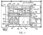
mold sections mold sections heaters 50 supported by acarriage 51 movable back and forth in themachine frame 39 onrails 52 androllers 53. Thecarriage 51 is driven by amotor 54 through acrank drive 55 or the like for shifting theheaters 50 back and forth as indicated by thearrows 56 in Fig. 11. - A
control panel 57 forms part of the apparatus, but not of the invention. The panel may include a suction source. - Referring to Fig. 11, the previously used reference numbers, especially those used in Fig. 10 are also used in Fig. 11. The
heaters 50 mounted to thecarriage 51 are movable back and forth in the guide rails 52 as indicated by thearrows 56 through amotor 54 and a crank orsimilar drive 55. Themotor 54 is mounted on abracket 57 which in turn is secured to crossbars 58 mounted to themachine frame 39. A guard rail orfence 59 surrounds the machine. Atemperature control device 60 including heaters and cooling elements for the fluids passing through the above mentioned heating and cooling ducts are incorporated in thetemperature control device 60. - The apparatus shown in Figs. 10 and 11 operates in such a way that the flip-flop table or
plate 47 hinged at 46 to the machine frame post 45 can alternately cooperate with one set or the other set ofmold sections carrier plate 47 in one horizontal position and vice versa with thecarrier plate 47 in another horizontal position in the machine frame. During tilting, the table orplate 47 through an angle of 180° the heating devices are moved into the out of the way position shown in Fig. 11. - The operation of the apparatus shown in Figs. 10 and 11 will now be described in more detail with reference to Figs. 12 to 19, wherein components already described above with reference to Fig. 1 will not be described again.
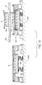
- In Fig. 12, the mold section on the left-hand table 40 has been loaded with a
cover sheet 8 while pressure is applied in the right-hand section of the apparatus corresponding to Fig. 5 described above. The springs exert a steady force for the laminating and bonding of the folded sheet edge to the back of the substrate. Asubstrate 4 has been loaded onto themold section 48. - In Fig. 13 the
heaters 50 have been brought into the position for heating thesubstrate 4 and thesheet 8. For this purpose, the table 40 would be in a higher position than shown in Fig. 13. Thus, these Figs. are not intended to be to scale. - In Fig. 14, the heating continues, but the compression in the right-hand section is such that the
folding devices 13 are ready to be moved out of the way corresponding to Fig. 6. However, in Fig. 14, the central mold member is lowered by its own piston cylinder device surrounded by thesprings 27 which are fully compressed in this position. The flip-flop plate or table 47 is ready to be moved counterclockwise as indicated by thedouble arrow 61. The drive means for theplate 47 are not shown in detail since they are conventional. For example, an electric motor driving a sprocket connected to thehinge 46 through a sprocket chain could move alternately clockwise and counterclockwise within the rhythm of the production sequence as controlled by thecontrol panel 57. - In Fig. 15 the
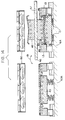
folding devices 13 have been moved out of the way corresponding to Fig. 7. In Fig. 16 the flip-flop plate 47 has been moved through an angle of 180° around thehinge 46, whereby the formerly upwardly facingmold section 48 now faces downwardly and the formerly downwardly facingmold section 49 faces upwardly, so that the now finishedtrim panel 62 can be removed by an operator. Thecentral mold section 43 will now be lowered to perform the initial folding of the sheet edge as described above with reference to Fig. 5. The right-hand side is ready for receiving a sheet to be placed manually by an operator. For this purpose the right-hand portion will be brought to its upper position by its respective drive. By this time the turntable has made its total 180° turn. The left lower table moves up until the lower mold is pushed down for cooperation with themold section 48 against the force of the springs to perform the partial folding of the sheet edge as described with reference to Fig. 5. Fig. 17 shows the further folding step with the folding devices moved inwardly corresponding to Fig. 4. The right-hand portion is still ready to receive a new cover sheet. - In Fig. 18, the left-hand portion currently functions as described above with reference to Fig. 5, whereby low pressure bonding takes place over the laminating area between the substrate and the cover sheet and also for the edge laminating and bonding.
- Incidentally, safety devices such as so-called light curtains, will be provided in the machine frame shown in Figs. 10 and 11 to protect an operator who will be merely required to insert prelaminated substrates and precut cover sheets and remove finished trim panels.
- In Fig. 19 the finished
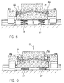
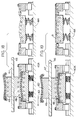
trim panel 62 is now removed as indicated by thearrow 63 while the laminating takes place in the lower left-hand portion as described above with reference to Fig. 5. Anew precut sheet 8 will now be inserted into the right-hand portion of Fig. 19. The operation is repeated starting with Fig. 12. - Figs. 20 to 26 show a further embodiment of the present apparatus for practicing the production method according to the invention. In this embodiment the
cover sheet 64 and thesubstrate 65 do not need to have different dimensions. However, thecover sheet edge 64A and thesubstrate rim 65A form together abrim 66. Preferably, thesubstrate rim 65A is thinner than the substrate itself. Thus, a folding around the transition area 64B between thebrim 66 and the thicker substrate section is facilitated. Afirst tool 67 which may form a mold section having itsown drive 68, such as a piston cylinder drive shown in Fig. 21, is provided with atucking rim 67A having aramp 67B. - Fig. 21 shows the
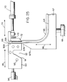
tool 67 of Fig. 20 in a cooperation position with asecond tool 69 having itsown drive 70 in the form of a piston cylinder device. Apiston rod 71 carries aheating block 72 heated by aheater 73. Thepiston cylinder device 70 moves the heating block with its heater back and forth as indicated by thearrow 74. Theupper end 72A of theheating block 72 is connected through a heat insulating piece 75 to the free end of thepiston rod 71. The second tool also includes acounterholder 76 having itself aramp 77 andcooling ducts 78. Thecounterholder 76 is mounted by abracket 79 to amachine frame 80. - In Fig. 22, the heating has been completed, and the
tool 67 has been moved down by itsdrive 68 as indicated by thedouble arrow 81 from the level shown in Figs. 20 and 21 to a lower level shown in Figs. 22 and 23. At the lower level, afolding tool 82 having aramp 83 and afolding groove 84 with itsown ramp 85 is movable back and forth horizontally as indicated by thearrow 86 by its own drive means not shown, but corresponding, for example, to thepiston cylinder device 70 of Fig. 21. Thefolding tool 82 has also coolingducts 87. - In Fig. 23, the
folding tool 82 has been moved to the right as indicated by thearrow 88, whereby thebrim 66 is folded through an angle of 90° as shown. - Fig. 24 shows how the
tool 67 is moved up as indicated by thearrow 89 with the aid of itsown drive 68 shown in Fig. 21. Thus, the tucking rim 67A moves into thegroove 84, whereby the tworamps tool 67 is lowered after the folding has been completed, whereupon the finished trim panel can be removed from the holding surface of thetool 67. - Figs. 25 and 26 illustrate a modified
counterholder 90 cooperating with thetool 67 and theheater 72 as described above. Thecounter holder 90 has acounterholding surface 90A and aramp 91 that cooperates with theramp 67B in the completion of the folding as shown in Fig. 26. Theramp 91 leads into a tuckinggroove 92 that receives thetucking edge 67A of thetool 67 for the completion of the folding. Thecounter holder 90 is also provided withcooling ducts 93 and has itsown drive 94 movable back and forth in the direction of thearrow 95. After the brim has been folded through 90° by the movement of thecounterholder 90 to the right as indicated by thearrow 95, thetool 67 moves up as indicated by thearrow 96 to complete the fold. Thedrives 70 and 97 will be driven in synchronism toward and away from each other. Thetool 67 may actually remain at the same level if thecounterholder 90 is also movable vertically up and down. - Although the invention has been described with reference to specific example embodiments, it will be appreciated that it is intended to cover all modifications and equivalents within the scope of the appended claims.
Claims (31)
- An apparatus for producing a trim panel having at least a substrate and a cover sheet laminated to said substrate with a sheet edge folded around a substrate rim onto a back of said substrate, comprising a first laminating mold section having a substrate holding first surface area, a second laminating mold section including a central mold member having a cover sheet supporting second surface area, first drive means for moving said first mold section and said central mold member relative to each other in a first direction for laminating, said second mold section further comprising at least one edge folding means mounted for movement in a second direction extending perpendicularly to said first direction, said at least one edge folding means having a third surface area for supporting said sheet edge when said central mold member and said at least one edge folding means are in a starting position for a laminating and edge folding operation, and second drive means for moving said edge folding means back and forth in said second direction when said central mold member is in a recessed position relative to said third surface, whereby a folding member of said at least one one edge folding means can move behind said central mold member thereby folding said sheet edge onto said back of said substrate around said rim of said substrate, whereby said central mold member can move partly toward said first laminating mold section against said folding member to thereby press said sheet edge against said back of said substrate.
- The apparatus of claim 1, further comprising elastically yielding support means for supporting said central mold member, said first drive means guiding said central mold member in said first direction, when said central mold member is driven by said first drive means, said support means storing a compression force for laminating.
- The apparatus of claim 2, wherein said first drive means comprise piston cylinder drives including piston rods for guiding and driving said central mold member, and wherein said elastically yielding support means comprise compression springs surrounding said piston rods, said compression springs holding said central mold member in said starting position in the absence of a driving force applied by said piston cylinder drives.
- The apparatus of claim 3, wherein in said starting position at least a portion of said second surface area of said central mold member is level with said third surface area of said edge folding means.
- The apparatus of claim 1, further comprising guide means for guiding said at least one edge folding means in said second direction when said edge folding means are driven by said second drive means in said second direction.
- The apparatus of claim 1, further comprising heater means for preheating said substrate and said cover sheet while said substrate is held by said upper mold section and said cover sheet is supported by said central mold member.
- The apparatus of claim 1, wherein said first laminating mold section is arranged above said second laminating mold section, wherein said first direction is vertical and said second direction is horizontal.
- The apparatus of claim 1, further comprising a frame, two sets of said first laminating mold section and two sets of said second laminating mold section arranged in said frame for movement relative to each other, and heater means for heating substrates held by said first laminating mold sections and for heating cover sheets supported by said second laminating mold sections.
- The apparatus of claim 8, further comprising a carrier plate for carrying said two sets of first mold sections, a machine frame member, hinge means for securing said carrier plate to said machine frame member so that said carrier plate is tiltable through an angle of at least 180°, wherein said two sets of said first laminating mold sections are secured to opposite sides of said carrier plate, and wherein said two sets of second laminating mold sections are so positioned that one set of second laminating mold sections is ready for loading while the other cooperates with one of said first mold sections on said carrier plate in one horizontal position and vice versa with said carrier plate in another horizontal position in said frame.
- The apparatus of claim 9, further comprising heater means positioned for heating substrates and cover sheets on any one of said first and second laminating mold sections, and means for moving said heater back and forth.
- The apparatus of claim 1, further comprising means connected to said first laminating mold sections, to said second laminating mold sections, and to said at least one edge folding means for individually controlling the temperature of said mold sections and of said folding means.
- The apparatus of claim 1, wherein said folding member of said at least one edge folding means comprises a folding finger having said third surface on a first side thereof, a projection with a slanted surface on a second side of said folding finger opposite said first side, and a tucking groove below said first side of said folding finger.
- The apparatus of claim 12, wherein said second surface area of said central mold member has a contour for shaping said trim panel, said central mold member comprising a tucking rim for cooperation with said tucking groove of said folding finger.
- The apparatus of claim 12, wherein said folding finger comprises a sheet positioning rim on said first side of said folding finger for initially precisely positioning a precut sheet.
- An apparatus for producing a trim panel having at least a substrate and a cover sheet laminated to said substrate with a sheet edge folded around a substrate rim onto a back of said substrate, comprising a laminating first mold member, a laminating second mold member, and at least one edge folding third member, said first mold member having a substrate holding first surface, said second mold member having a cover sheet supporting second surface, said third member having a sheet edge supporting third surface, said first surface having an area smaller than said substrate, said substrate rim extends outside said first surface area, said second surface having an area larger than said substrate so that said sheet edge extends outside said first surface area and outside said substrate, said third surface extending outside said second surface and at a first level in common with at least a portion of said second surface when said three members are in a starting position relative to each other, drive means for moving said three members relative to each other for cooperation with each other in a laminating and edge folding operation, whereby in a first laminating step said substrate and said cover sheet are laminated to each other at a second level sufficiently below said first level for said third member to reach behind said back of said substrate, thereby folding said sheet edge around said substrate rim and against said back of said substrate, said drive means including means for pressing said substrate back against said third member for laminating said sheet edge against said substrate back.
- The apparatus of claim 15, further comprising temperature control means for individually controlling the temperature of said three members.
- The apparatus of claim 15, wherein said drive means comprise first drive means for moving said first and second mold members vertically relative to each other and second drive means for moving said third member horizontally, said first drive means including a power drive and compression springs supporting said second mold member, whereby an expansion force is stored in said compression springs when said power drive moves said first and second members in a spring compressing direction, said expansion force providing a laminating pressure when said power drive moves in a spring release direction.
- A method for producing a trim panel having at least a substrate and a cover sheet laminated to said substrate with a sheet edge folded around a substrate rim onto a back of said substrate, comprising the following steps:(a) preparing said substrate and cover sheet so that said cover sheet has an area larger than said substrate whereby a sheet edge projects outside said substrate rim and separately loading said substrate and cover sheet into a mold,(b) heating said substrate and controlling the temperature of said cover sheet sufficiently for a following laminating step,(c) pressing a first mold member against a second mold member for first laminating said cover sheet to said substrate, whereby said substrate rim is positioned at such a level that a folding member can reach behind said substrate rim,(d) moving said folding member into a position behind said substrate rim, thereby folding said sheet edge against said back of said substrate,(e) moving at least one of said folding member and said second mold member toward each other to apply a pressure to said sheet edge for second laminating said sheet edge to said substrate back,(f) moving said second mold member out of a moving range of said folding member and moving said folding member out from behind said second mold member, and(g) moving said first and second mold members apart and removing the trim panel.
- The method of claim 18, wherein three different pressures are applied during said first and second laminating.
- The method of claim 1, wherein said folding begins as said step (c) when said sheet edge passes said folding member, wherein a fold over takes place in said step (d), and wherein a tucking operation is performed in said step (e).
- An apparatus for producing trim panels having at least a substrate and a cover sheet laminated to said substrate with a cover sheet edge folded around a substrate rim onto a back of said trim panel, comprising first tool means for holding a prelaminated panel, said first tool means having a tucking edge, said sheet edge and said substrate rim forming a brim protruding from said tucking edge, first drive means for moving said first tool means in a first direction, second tool means for heating said substrate rim forming part of said brim, second drive means for moving said second tool means in a second direction extending perpendicularly to said first direction, whereby movement of said second tool means in said second direction folds said brim through an angle of at least 90°, said movement of said second tool means positioning said second tool means for cooperation with said tucking edge of said first tool means when said first drive means move said first tool means in said first direction into engagement with said second tool means to complete a folding operation.
- The apparatus of claim 21, wherein said second tool means comprise means for backing said protruding cover sheet edge opposite said heating means, said second drive means pressing said heating tool means and said backing means toward each other across a gap to press said substrate rim against said cover sheet edge backed in said gap by said backing means, said second tool means further comprising fold completion means for folding said brim through a further angle of 90°, said fold completion means cooperating with said tucking rim of said first tool means for making a complete fold of said brim to form said trim panel.
- The apparatus of claim 22, wherein said tucking tool rim of said first tool means comprises a first ramp, said backing means of said second tool means having a second ramp for cooperation with said first ramp of said first tool means during a heating operation, said fold completion means of said second tool means having a third ramp for cooperation with said first ramp during a fold completion operation.
- The apparatus of claim 22, wherein said fold completion means of said second tool means comprise a folding groove for cooperating with said tucking rim of said first tool means during a fold completion operation.
- The apparatus of claim 23, wherein said second ramp of said second tool means first pushes said brim formed by said sheet edge and said substrate rim, through said angle of at least 90°.
- The apparatus of claim 22, wherein said first drive means move said first tool means vertically, wherein said second drive means move said second heating tool means horizontally, and wherein said second drive means comprise first and second horizontally effective piston cylinder drives for operating said backing means and said heating tool means.
- The apparatus of claim 22, wherein said backing means of said second tool means is arranged at a first horizontal level, wherein said second heating tool means is arranged for horizontal movement by said second drive means substantially in said first horizontal level, and wherein said fold completion means is arranged at a second horizontal level for cooperation with said tucking rim of said first tool means, said first drive means moving said first tool means vertically into cooperation with said second tool means at said first horizontal level and with said fold completion means at said second horizontal level.
- The apparatus of claim 27, wherein said backing means of said second tool means are stationary at said first horizontal level, and wherein said fold completion means are arranged at said second horizontal level below said first horizontal level.
- A method for producing a trim panel having at least a substrate and a cover sheet laminated to said substrate with a sheet edge folded around a substrate rim onto a back of said trim panel, comprising the following steps:(a) laminating said cover sheet to said substrate to form a prelaminated panel, so that said sheet edge and said substrate rim together form a panel brim,(b) holding said panel so that said panel brim protrudes from a tucking rim of a panel holding tool,(c) heating said substrate rim sufficiently for a laminating and bonding operation,(d) folding said protruding panel brim through an angle of at least 90°, and(e) moving said tucking rim into cooperation with a fold completion means for completing a fold.
- The method of claim 29, further comprising cooling said protruding sheet edge while heating said protruding substrate rim for protecting said cover sheet against damage by the heating of the substrate rim.
- The method of claim 29, making said substrate rim thinner than said substrate so that said panel brim is thinner than said prelaminated panel, and forming said fold where said thinner brim merges into said prelaminated panel.
Applications Claiming Priority (3)
| Application Number | Priority Date | Filing Date | Title |
|---|---|---|---|
| US996901 | 1992-12-23 | ||
| US07/996,901 US5324384A (en) | 1992-12-23 | 1992-12-23 | Apparatus for laminating a trim panel and folding a brim around the panel rim |
| PCT/EP1994/002069 WO1995035197A1 (en) | 1992-12-23 | 1994-06-22 | Method and apparatus for folding a brim of a laminated panel around a panel rim to form a trim panel |
Publications (1)
| Publication Number | Publication Date |
|---|---|
| EP0603498A1 true EP0603498A1 (en) | 1994-06-29 |
Family
ID=26070110
Family Applications (1)
| Application Number | Title | Priority Date | Filing Date |
|---|---|---|---|
| EP93117255A Withdrawn EP0603498A1 (en) | 1992-12-23 | 1993-10-25 | Method and apparatus for folding a brim of a laminated panel around a panel rim to form a trim panel |
Country Status (4)
| Country | Link |
|---|---|
| US (1) | US5324384A (en) |
| EP (1) | EP0603498A1 (en) |
| JP (1) | JP2833668B2 (en) |
| WO (1) | WO1995035197A1 (en) |
Cited By (19)
| Publication number | Priority date | Publication date | Assignee | Title |
|---|---|---|---|---|
| EP0637500A2 (en) * | 1993-07-16 | 1995-02-08 | SATURNO S.p.A MATERIE PLASTICHE | Process for producing vehicle interior panels, device implementing the process, and panel produced thereby |
| DE9420596U1 (en) * | 1994-12-23 | 1995-03-09 | Kiefel Gmbh Paul | Folding device for trim parts |
| EP0686478A1 (en) * | 1994-06-08 | 1995-12-13 | Gerhard Pirchl | Lined metal article and method for its manufacture |
| WO1995035197A1 (en) * | 1992-12-23 | 1995-12-28 | Kodama Chemical Industry Co., Ltd. | Method and apparatus for folding a brim of a laminated panel around a panel rim to form a trim panel |
| EP0712759A1 (en) * | 1994-11-18 | 1996-05-22 | Kasai Kogyo Co., Ltd. | Automotive upholstery components and method for making the same |
| WO1997006939A1 (en) * | 1995-08-21 | 1997-02-27 | G.O.R. Applicazioni Speciali S.P.A. | Thermoforming mold with trimming movable side blades |
| FR2738769A1 (en) * | 1995-09-19 | 1997-03-21 | Sotira | Mould for enclosing insert in thermoplastic reinforcing |
| EP0792734A3 (en) * | 1996-03-01 | 1998-08-05 | Volkswagen Aktiengesellschaft | Method and device for folding a cover sheet around an edge |
| US6019869A (en) * | 1996-09-25 | 2000-02-01 | Fifield; Steven | Laminating machine |
| WO2000028861A1 (en) * | 1998-11-18 | 2000-05-25 | De-Ta Spa | Method to cover padded components for seats and relative device |
| EP1008430A1 (en) * | 1997-02-10 | 2000-06-14 | Kaneka Corporation | Skin-carrying in-mold expanded molded body manufacturing method, the molded body, and mold used for manufacturing the same |
| FR2815569A1 (en) * | 2000-10-19 | 2002-04-26 | Eurostyle Sa | Edge-forming of plastic component over-molded onto decor by injection, trims projecting edge, heats it and folds it down using plungers |
| WO2005037586A1 (en) * | 2003-09-30 | 2005-04-28 | Michael Greidenweis | Covering method and covering device |
| FR2909306A3 (en) * | 2006-12-01 | 2008-06-06 | Renault Sas | Thermoformed piece and reinforcement element assembling arrangement for motor vehicle, has thermoformed piece whose end is folded around end of reinforcement element, so that side of piece contacts with side of end of reinforcement element |
| DE102007040879A1 (en) * | 2007-08-29 | 2009-03-05 | Iac Group Gmbh | Lining part i.e. inner lining, producing method for door of motor vehicle, involves tilting edges of covering material piece by tilting unit around edges of carrier component to wrapping, and pressing wrapping at front surface of component |
| DE102008006715A1 (en) * | 2008-01-30 | 2009-08-06 | Faurecia Innenraum Systeme Gmbh | Method for laminating a multilayer plastic component |
| US20140333097A1 (en) * | 2007-08-10 | 2014-11-13 | Johnson Controls Technology Company | Vehicle panel |
| DE102006054079B4 (en) | 2005-12-13 | 2021-11-25 | Lear Corp. | Method of forming an article covered with a textile |
| EP3915932A4 (en) * | 2020-01-07 | 2022-11-23 | Toyoda Iron Works Co., Ltd. | Manufacturing device and manufacturing method for component with outer layer |
Families Citing this family (37)
| Publication number | Priority date | Publication date | Assignee | Title |
|---|---|---|---|---|
| JP2851244B2 (en) * | 1994-02-09 | 1999-01-27 | 児玉化学工業株式会社 | Multilayer laminate and method of manufacturing multilayer laminate panel |
| US5641379A (en) * | 1994-04-18 | 1997-06-24 | Cesano; Franco | Apparatus for producing a thermoplastic article having an undercut cross-section |
| US6096166A (en) * | 1994-07-12 | 2000-08-01 | Liou; Tim | Speaker cover assembly apparatus |
| JPH08267592A (en) * | 1995-03-31 | 1996-10-15 | Sintokogio Ltd | Decorative element bonding apparatus |
| US5718791A (en) * | 1995-06-05 | 1998-02-17 | R + S Stanztechnik Gmbh | Method of laminating a trim panel and folding a cover sheet edge around the panel rim |
| JP3189969B2 (en) * | 1995-07-21 | 2001-07-16 | 新東工業株式会社 | Method and apparatus for embedding decorative wood |
| US5895624A (en) * | 1996-06-18 | 1999-04-20 | Android Industries Of Michigan, Llc | Method and apparatus for forming thick wall plastic sheets having formable decorative film layers |
| US6524506B2 (en) | 2000-12-26 | 2003-02-25 | R+S Technik Gmbh | Combination tool for edge-folding and cutting a panel rim |
| EP1371476A1 (en) * | 2002-02-15 | 2003-12-17 | R+S Technik GmbH | Apparatus for manufacturing vehicle interior parts |
| JP3940413B2 (en) * | 2004-10-05 | 2007-07-04 | 小島プレス工業株式会社 | Sheet press machine |
| US7866364B2 (en) * | 2006-04-28 | 2011-01-11 | Hewlett-Packard Development Company, L.P. | Fabrication tool for bonding |
| US20080003322A1 (en) * | 2006-05-22 | 2008-01-03 | Lear Corporation | Vacuum, wrap, and trim system for the manufacturer of components |
| US20080029204A1 (en) * | 2006-08-03 | 2008-02-07 | Jeremy Knopow | Machine and method for assembling a fabric sweeper |
| US7597371B2 (en) * | 2007-05-01 | 2009-10-06 | Toyota Motor Engineering & Manufacturing North America, Inc. | Lead-in for trim assembly |
| US7666269B2 (en) * | 2007-05-18 | 2010-02-23 | The Boeing Company | Methods for edge-wrapping a panel |
| DE102008009762A1 (en) * | 2008-02-19 | 2009-08-20 | Faurecia Innenraum Systeme Gmbh | Device and method for laminating a carrier layer with a decorative layer |
| US8012290B2 (en) * | 2008-06-30 | 2011-09-06 | Herbert Olbrich Gmbh & Co. Kg | Method and apparatus for producing a three-dimensionally molded, laminated article with transfer-printed surface decoration |
| DE102011015818A1 (en) * | 2011-04-01 | 2012-10-04 | Faurecia Innenraum Systeme Gmbh | Umbugverfahren, Umbugvorrichtung and component with Umbug |
| KR101353994B1 (en) * | 2011-08-23 | 2014-01-21 | 삼성디스플레이 주식회사 | Apparatus for assembly film and glass |
| US9511690B2 (en) | 2012-04-23 | 2016-12-06 | Global Ip Holdings, Llc | Cargo management system including a vehicle load floor having a cellulose-based core and made by a composite, compression molding process and having a wood grain finish |
| US9527268B2 (en) | 2012-04-23 | 2016-12-27 | Global Ip Holdings, Llc | Method of making a sandwich-type composite panel having a cellulose-based core and a living hinge and panel obtained by performing the method |
| US9539749B2 (en) * | 2012-05-15 | 2017-01-10 | Blackberry Limited | Formable inserts and related methods |
| WO2014061457A1 (en) * | 2012-10-15 | 2014-04-24 | シャープ株式会社 | Molding device, molding device unit, and molding method |
| DE102012020484B4 (en) | 2012-10-18 | 2023-07-20 | Faurecia Innenraum Systeme Gmbh | Process for producing a component and component having at least two layers |
| US10618203B2 (en) | 2013-02-08 | 2020-04-14 | Global Ip Holdings, Llc | Method of making a trimmed, laminated trim component |
| US10532499B2 (en) | 2013-02-08 | 2020-01-14 | Global Ip Holdings, Llc | Method of making a laminated trim component |
| US10166704B2 (en) | 2013-02-08 | 2019-01-01 | Global Ip Holdings, Llc | Method of making a laminated trim component at a pair of spaced first and second molding stations |
| US10279512B2 (en) | 2013-02-08 | 2019-05-07 | Global Ip Holdings, Llc | Method of making a laminated trim component at a molding station |
| US10076856B2 (en) * | 2015-06-15 | 2018-09-18 | International Automotive Components Group North America, Inc. | Manufacture of an article having a decorative cover sheet overlying a substrate |
| JP6618288B2 (en) * | 2015-07-17 | 2019-12-11 | スリーエム イノベイティブ プロパティズ カンパニー | Sticking device, sticking method and film |
| DE102017104638B4 (en) | 2017-03-06 | 2022-04-07 | Olbrich Gmbh | Device for folding over excess material from a lamination around an edge area of a workpiece and a corresponding method |
| WO2019239437A1 (en) * | 2018-06-15 | 2019-12-19 | Benassi, Gabriella | Automatic machine for coating panels with leather or fabrics |
| US11518160B2 (en) * | 2019-08-29 | 2022-12-06 | Inteva Products, Llc | Method for non-contact adhesive activation and wrapping of a decorative skin to a part having curved surfaces and a part formed by the method |
| CN112453251B (en) * | 2020-10-30 | 2022-06-21 | 惠州市诚业家具有限公司 | Automatic forming process and forming die for storage basket |
| US11518072B2 (en) | 2020-12-02 | 2022-12-06 | Global Ip Holdings, Llc | Automated manufacturing method and system and in-mold coated plastic article produced thereby |
| US11618188B2 (en) | 2020-12-02 | 2023-04-04 | Global Ip Holdings, Llc | Automated manufacturing method and system and in-mold coated plastic article produced thereby |
| KR20230020690A (en) | 2021-08-04 | 2023-02-13 | 현대모비스 주식회사 | Press device for manufacturing crash pads for vehicles equipped with real wood seats |
Citations (5)
| Publication number | Priority date | Publication date | Assignee | Title |
|---|---|---|---|---|
| US2284833A (en) * | 1938-07-06 | 1942-06-02 | Imp Knife Company Inc | Method and apparatus for making knife handles and component parts thereof |
| US3580770A (en) * | 1967-01-31 | 1971-05-25 | Tripro Inc | Method for producing laminated structures |
| US4174988A (en) * | 1976-01-30 | 1979-11-20 | Chivas Products Ltd. | Method and apparatus for making padded straps |
| US4537646A (en) * | 1983-06-10 | 1985-08-27 | Hoyle James E | Lap desk |
| EP0533311A1 (en) * | 1991-09-17 | 1993-03-24 | Kasai Kogyo Co., Ltd. | Bonding device and bonding process for fabricating an interior component |
Family Cites Families (8)
| Publication number | Priority date | Publication date | Assignee | Title |
|---|---|---|---|---|
| US3075862A (en) * | 1956-09-25 | 1963-01-29 | Volkswagenwerk Ag | Cover panels and method of manufacture |
| NL296494A (en) * | 1962-08-11 | 1900-01-01 | ||
| IT1120348B (en) * | 1979-04-27 | 1986-03-19 | Morello Sergio | PROCEDURE FOR THE MANUFACTURE OF CLADDING PANELS AND PANELS OBTAINED BY SUCH PROCEDURE |
| US4357723A (en) * | 1979-05-18 | 1982-11-09 | Knoll International, Inc. | Apparatus and method for upholstering a rigid chair shell |
| US4617081A (en) * | 1985-02-04 | 1986-10-14 | Bleau Charles D | Side flap fold apparatus for a disk envelope |
| US4634483A (en) * | 1985-03-15 | 1987-01-06 | Stanztechnik Gmbh R & S | Apparatus for performing several different operations on an initially flat work piece |
| US4839126A (en) * | 1987-09-14 | 1989-06-13 | Griesdorn Carl P | Method and apparatus for folding the edges of a sheet of material |
| US5324384A (en) * | 1992-12-23 | 1994-06-28 | R & S Stanztechnik Gmbh | Apparatus for laminating a trim panel and folding a brim around the panel rim |
-
1992
- 1992-12-23 US US07/996,901 patent/US5324384A/en not_active Expired - Fee Related
-
1993
- 1993-10-25 EP EP93117255A patent/EP0603498A1/en not_active Withdrawn
-
1994
- 1994-06-22 JP JP8501516A patent/JP2833668B2/en not_active Expired - Lifetime
- 1994-06-22 WO PCT/EP1994/002069 patent/WO1995035197A1/en unknown
Patent Citations (5)
| Publication number | Priority date | Publication date | Assignee | Title |
|---|---|---|---|---|
| US2284833A (en) * | 1938-07-06 | 1942-06-02 | Imp Knife Company Inc | Method and apparatus for making knife handles and component parts thereof |
| US3580770A (en) * | 1967-01-31 | 1971-05-25 | Tripro Inc | Method for producing laminated structures |
| US4174988A (en) * | 1976-01-30 | 1979-11-20 | Chivas Products Ltd. | Method and apparatus for making padded straps |
| US4537646A (en) * | 1983-06-10 | 1985-08-27 | Hoyle James E | Lap desk |
| EP0533311A1 (en) * | 1991-09-17 | 1993-03-24 | Kasai Kogyo Co., Ltd. | Bonding device and bonding process for fabricating an interior component |
Cited By (24)
| Publication number | Priority date | Publication date | Assignee | Title |
|---|---|---|---|---|
| WO1995035197A1 (en) * | 1992-12-23 | 1995-12-28 | Kodama Chemical Industry Co., Ltd. | Method and apparatus for folding a brim of a laminated panel around a panel rim to form a trim panel |
| EP0637500A2 (en) * | 1993-07-16 | 1995-02-08 | SATURNO S.p.A MATERIE PLASTICHE | Process for producing vehicle interior panels, device implementing the process, and panel produced thereby |
| EP0637500A3 (en) * | 1993-07-16 | 1995-11-29 | Saturno Spa | Process for producing vehicle interior panels, device implementing the process, and panel produced thereby. |
| EP0686478A1 (en) * | 1994-06-08 | 1995-12-13 | Gerhard Pirchl | Lined metal article and method for its manufacture |
| EP0712759A1 (en) * | 1994-11-18 | 1996-05-22 | Kasai Kogyo Co., Ltd. | Automotive upholstery components and method for making the same |
| US5695865A (en) * | 1994-11-18 | 1997-12-09 | Kasai Kogyo Co., Ltd. | Automotive upholstery components and method for making the same |
| DE9420596U1 (en) * | 1994-12-23 | 1995-03-09 | Kiefel Gmbh Paul | Folding device for trim parts |
| WO1997006939A1 (en) * | 1995-08-21 | 1997-02-27 | G.O.R. Applicazioni Speciali S.P.A. | Thermoforming mold with trimming movable side blades |
| FR2738769A1 (en) * | 1995-09-19 | 1997-03-21 | Sotira | Mould for enclosing insert in thermoplastic reinforcing |
| EP0792734A3 (en) * | 1996-03-01 | 1998-08-05 | Volkswagen Aktiengesellschaft | Method and device for folding a cover sheet around an edge |
| US6019869A (en) * | 1996-09-25 | 2000-02-01 | Fifield; Steven | Laminating machine |
| EP1008430A1 (en) * | 1997-02-10 | 2000-06-14 | Kaneka Corporation | Skin-carrying in-mold expanded molded body manufacturing method, the molded body, and mold used for manufacturing the same |
| EP1008430A4 (en) * | 1997-02-10 | 2002-02-20 | Kaneka Corp | Skin-carrying in-mold expanded molded body manufacturing method, the molded body, and mold used for manufacturing the same |
| WO2000028861A1 (en) * | 1998-11-18 | 2000-05-25 | De-Ta Spa | Method to cover padded components for seats and relative device |
| FR2815569A1 (en) * | 2000-10-19 | 2002-04-26 | Eurostyle Sa | Edge-forming of plastic component over-molded onto decor by injection, trims projecting edge, heats it and folds it down using plungers |
| WO2005037586A1 (en) * | 2003-09-30 | 2005-04-28 | Michael Greidenweis | Covering method and covering device |
| DE102006054079B4 (en) | 2005-12-13 | 2021-11-25 | Lear Corp. | Method of forming an article covered with a textile |
| FR2909306A3 (en) * | 2006-12-01 | 2008-06-06 | Renault Sas | Thermoformed piece and reinforcement element assembling arrangement for motor vehicle, has thermoformed piece whose end is folded around end of reinforcement element, so that side of piece contacts with side of end of reinforcement element |
| US20140333097A1 (en) * | 2007-08-10 | 2014-11-13 | Johnson Controls Technology Company | Vehicle panel |
| DE102007040879A1 (en) * | 2007-08-29 | 2009-03-05 | Iac Group Gmbh | Lining part i.e. inner lining, producing method for door of motor vehicle, involves tilting edges of covering material piece by tilting unit around edges of carrier component to wrapping, and pressing wrapping at front surface of component |
| DE102008006715A1 (en) * | 2008-01-30 | 2009-08-06 | Faurecia Innenraum Systeme Gmbh | Method for laminating a multilayer plastic component |
| WO2009095256A1 (en) * | 2008-01-30 | 2009-08-06 | Faurecia Innenraum Systeme Gmbh | Process for producing a moulding |
| US8562779B2 (en) | 2008-01-30 | 2013-10-22 | Faurecia Innenraum Systeme Gmbh | Method for manufacturing a moulded article |
| EP3915932A4 (en) * | 2020-01-07 | 2022-11-23 | Toyoda Iron Works Co., Ltd. | Manufacturing device and manufacturing method for component with outer layer |
Also Published As
| Publication number | Publication date |
|---|---|
| US5324384A (en) | 1994-06-28 |
| WO1995035197A1 (en) | 1995-12-28 |
| JPH09504489A (en) | 1997-05-06 |
| JP2833668B2 (en) | 1998-12-09 |
Similar Documents
| Publication | Publication Date | Title |
|---|---|---|
| US5324384A (en) | Apparatus for laminating a trim panel and folding a brim around the panel rim | |
| US5718791A (en) | Method of laminating a trim panel and folding a cover sheet edge around the panel rim | |
| US7699595B2 (en) | Method and apparatus for molding a laminated trim component without use of slip frame | |
| JPS61169347A (en) | Interior constituent for automobile | |
| KR101999990B1 (en) | Automation equipment for enveloping interior trim | |
| EP0569846A2 (en) | Apparatus for producing trim panels and method for securing such trim panels to a support | |
| CN112265207B (en) | Automobile trunk ornament production line and production method thereof | |
| KR200299852Y1 (en) | Device of joining interior material for a car door trim | |
| CN111716868B (en) | Covering machine for spare tire cover plate and processing technology of covering machine | |
| US4257840A (en) | Hot-press machine with facing layer carrying and setting apparatus | |
| JP2008100241A (en) | Press working method and press working apparatus | |
| KR102588207B1 (en) | Skin Thermocompression Mold Device of Interior Materials of Automobile | |
| CN213291299U (en) | Blanking mechanism for thermal forming of blanket for automobile passenger | |
| JP3019745B2 (en) | Molding method and molding apparatus for laminated molded articles | |
| JP3222399B2 (en) | Resin sheet lamination molding equipment | |
| JP2662933B2 (en) | Skin integral molding method | |
| US20100140831A1 (en) | Molded object-forming apparatus and method | |
| JP2968682B2 (en) | Skin integral molding method and apparatus therefor | |
| EP1186454B1 (en) | Method for producing lined panels for motor-vehicles | |
| JP3745933B2 (en) | Method for forming laminated molded body | |
| JPH05111956A (en) | Rolling-in method of end section of laminated material | |
| JP3681100B2 (en) | Method and apparatus for molding laminated molded body | |
| JPH0711968Y2 (en) | A device for cutting and separating a package lid in an automatic molding device for a package lid | |
| JP2999943B2 (en) | Crimping jig | |
| JPH05162717A (en) | Vacuum packaging device |
Legal Events
| Date | Code | Title | Description |
|---|---|---|---|
| PUAI | Public reference made under article 153(3) epc to a published international application that has entered the european phase |
Free format text: ORIGINAL CODE: 0009012 |
|
| AK | Designated contracting states |
Kind code of ref document: A1 Designated state(s): DE FR GB |
|
| 17P | Request for examination filed |
Effective date: 19940707 |
|
| STAA | Information on the status of an ep patent application or granted ep patent |
Free format text: STATUS: THE APPLICATION HAS BEEN WITHDRAWN |
|
| 18W | Application withdrawn |
Withdrawal date: 19951123 |