EP0602594A1 - Device for trimming a flat product, particularly a multi-layer printed product - Google Patents
Device for trimming a flat product, particularly a multi-layer printed product Download PDFInfo
- Publication number
- EP0602594A1 EP0602594A1 EP93120130A EP93120130A EP0602594A1 EP 0602594 A1 EP0602594 A1 EP 0602594A1 EP 93120130 A EP93120130 A EP 93120130A EP 93120130 A EP93120130 A EP 93120130A EP 0602594 A1 EP0602594 A1 EP 0602594A1
- Authority
- EP
- European Patent Office
- Prior art keywords
- cellular wheel
- knife
- cell
- wheel
- knives
- Prior art date
- Legal status (The legal status is an assumption and is not a legal conclusion. Google has not performed a legal analysis and makes no representation as to the accuracy of the status listed.)
- Granted
Links
Images


Classifications
-
- B—PERFORMING OPERATIONS; TRANSPORTING
- B65—CONVEYING; PACKING; STORING; HANDLING THIN OR FILAMENTARY MATERIAL
- B65H—HANDLING THIN OR FILAMENTARY MATERIAL, e.g. SHEETS, WEBS, CABLES
- B65H29/00—Delivering or advancing articles from machines; Advancing articles to or into piles
- B65H29/26—Delivering or advancing articles from machines; Advancing articles to or into piles by dropping the articles
- B65H29/28—Delivering or advancing articles from machines; Advancing articles to or into piles by dropping the articles from mechanical grippers
-
- B—PERFORMING OPERATIONS; TRANSPORTING
- B26—HAND CUTTING TOOLS; CUTTING; SEVERING
- B26D—CUTTING; DETAILS COMMON TO MACHINES FOR PERFORATING, PUNCHING, CUTTING-OUT, STAMPING-OUT OR SEVERING
- B26D11/00—Combinations of several similar cutting apparatus
-
- B—PERFORMING OPERATIONS; TRANSPORTING
- B26—HAND CUTTING TOOLS; CUTTING; SEVERING
- B26D—CUTTING; DETAILS COMMON TO MACHINES FOR PERFORATING, PUNCHING, CUTTING-OUT, STAMPING-OUT OR SEVERING
- B26D7/00—Details of apparatus for cutting, cutting-out, stamping-out, punching, perforating, or severing by means other than cutting
- B26D7/06—Arrangements for feeding or delivering work of other than sheet, web, or filamentary form
- B26D7/0675—Arrangements for feeding or delivering work of other than sheet, web, or filamentary form specially adapted for piles of sheets
-
- B—PERFORMING OPERATIONS; TRANSPORTING
- B26—HAND CUTTING TOOLS; CUTTING; SEVERING
- B26D—CUTTING; DETAILS COMMON TO MACHINES FOR PERFORATING, PUNCHING, CUTTING-OUT, STAMPING-OUT OR SEVERING
- B26D7/00—Details of apparatus for cutting, cutting-out, stamping-out, punching, perforating, or severing by means other than cutting
- B26D7/18—Means for removing cut-out material or waste
- B26D7/1845—Means for removing cut-out material or waste by non mechanical means
- B26D7/1863—Means for removing cut-out material or waste by non mechanical means by suction
-
- B—PERFORMING OPERATIONS; TRANSPORTING
- B65—CONVEYING; PACKING; STORING; HANDLING THIN OR FILAMENTARY MATERIAL
- B65H—HANDLING THIN OR FILAMENTARY MATERIAL, e.g. SHEETS, WEBS, CABLES
- B65H2301/00—Handling processes for sheets or webs
- B65H2301/40—Type of handling process
- B65H2301/44—Moving, forwarding, guiding material
- B65H2301/447—Moving, forwarding, guiding material transferring material between transport devices
- B65H2301/4471—Grippers, e.g. moved in paths enclosing an area
- B65H2301/44712—Grippers, e.g. moved in paths enclosing an area carried by chains or bands
-
- Y—GENERAL TAGGING OF NEW TECHNOLOGICAL DEVELOPMENTS; GENERAL TAGGING OF CROSS-SECTIONAL TECHNOLOGIES SPANNING OVER SEVERAL SECTIONS OF THE IPC; TECHNICAL SUBJECTS COVERED BY FORMER USPC CROSS-REFERENCE ART COLLECTIONS [XRACs] AND DIGESTS
- Y10—TECHNICAL SUBJECTS COVERED BY FORMER USPC
- Y10S—TECHNICAL SUBJECTS COVERED BY FORMER USPC CROSS-REFERENCE ART COLLECTIONS [XRACs] AND DIGESTS
- Y10S83/00—Cutting
- Y10S83/929—Particular nature of work or product
- Y10S83/934—Book, being made, e.g. trimming a signature
-
- Y—GENERAL TAGGING OF NEW TECHNOLOGICAL DEVELOPMENTS; GENERAL TAGGING OF CROSS-SECTIONAL TECHNOLOGIES SPANNING OVER SEVERAL SECTIONS OF THE IPC; TECHNICAL SUBJECTS COVERED BY FORMER USPC CROSS-REFERENCE ART COLLECTIONS [XRACs] AND DIGESTS
- Y10—TECHNICAL SUBJECTS COVERED BY FORMER USPC
- Y10T—TECHNICAL SUBJECTS COVERED BY FORMER US CLASSIFICATION
- Y10T83/00—Cutting
- Y10T83/202—With product handling means
- Y10T83/2066—By fluid current
- Y10T83/207—By suction means
-
- Y—GENERAL TAGGING OF NEW TECHNOLOGICAL DEVELOPMENTS; GENERAL TAGGING OF CROSS-SECTIONAL TECHNOLOGIES SPANNING OVER SEVERAL SECTIONS OF THE IPC; TECHNICAL SUBJECTS COVERED BY FORMER USPC CROSS-REFERENCE ART COLLECTIONS [XRACs] AND DIGESTS
- Y10—TECHNICAL SUBJECTS COVERED BY FORMER USPC
- Y10T—TECHNICAL SUBJECTS COVERED BY FORMER US CLASSIFICATION
- Y10T83/00—Cutting
- Y10T83/202—With product handling means
- Y10T83/2092—Means to move, guide, or permit free fall or flight of product
- Y10T83/2183—Product mover including gripper means
- Y10T83/219—Rotating or oscillating product handler
-
- Y—GENERAL TAGGING OF NEW TECHNOLOGICAL DEVELOPMENTS; GENERAL TAGGING OF CROSS-SECTIONAL TECHNOLOGIES SPANNING OVER SEVERAL SECTIONS OF THE IPC; TECHNICAL SUBJECTS COVERED BY FORMER USPC CROSS-REFERENCE ART COLLECTIONS [XRACs] AND DIGESTS
- Y10—TECHNICAL SUBJECTS COVERED BY FORMER USPC
- Y10T—TECHNICAL SUBJECTS COVERED BY FORMER US CLASSIFICATION
- Y10T83/00—Cutting
- Y10T83/465—Cutting motion of tool has component in direction of moving work
- Y10T83/4766—Orbital motion of cutting blade
- Y10T83/4795—Rotary tool
- Y10T83/4847—With cooperating stationary tool
-
- Y—GENERAL TAGGING OF NEW TECHNOLOGICAL DEVELOPMENTS; GENERAL TAGGING OF CROSS-SECTIONAL TECHNOLOGIES SPANNING OVER SEVERAL SECTIONS OF THE IPC; TECHNICAL SUBJECTS COVERED BY FORMER USPC CROSS-REFERENCE ART COLLECTIONS [XRACs] AND DIGESTS
- Y10—TECHNICAL SUBJECTS COVERED BY FORMER USPC
- Y10T—TECHNICAL SUBJECTS COVERED BY FORMER US CLASSIFICATION
- Y10T83/00—Cutting
- Y10T83/647—With means to convey work relative to tool station
- Y10T83/654—With work-constraining means on work conveyor [i.e., "work-carrier"]
- Y10T83/6542—Plural means to constrain plural work pieces
- Y10T83/6544—End of work protrudes through aperture in carrier
-
- Y—GENERAL TAGGING OF NEW TECHNOLOGICAL DEVELOPMENTS; GENERAL TAGGING OF CROSS-SECTIONAL TECHNOLOGIES SPANNING OVER SEVERAL SECTIONS OF THE IPC; TECHNICAL SUBJECTS COVERED BY FORMER USPC CROSS-REFERENCE ART COLLECTIONS [XRACs] AND DIGESTS
- Y10—TECHNICAL SUBJECTS COVERED BY FORMER USPC
- Y10T—TECHNICAL SUBJECTS COVERED BY FORMER US CLASSIFICATION
- Y10T83/00—Cutting
- Y10T83/869—Means to drive or to guide tool
- Y10T83/8776—Constantly urged tool or tool support [e.g., spring biased]
- Y10T83/8778—Ledger blade
-
- Y—GENERAL TAGGING OF NEW TECHNOLOGICAL DEVELOPMENTS; GENERAL TAGGING OF CROSS-SECTIONAL TECHNOLOGIES SPANNING OVER SEVERAL SECTIONS OF THE IPC; TECHNICAL SUBJECTS COVERED BY FORMER USPC CROSS-REFERENCE ART COLLECTIONS [XRACs] AND DIGESTS
- Y10—TECHNICAL SUBJECTS COVERED BY FORMER USPC
- Y10T—TECHNICAL SUBJECTS COVERED BY FORMER US CLASSIFICATION
- Y10T83/00—Cutting
- Y10T83/869—Means to drive or to guide tool
- Y10T83/8789—With simple revolving motion only
- Y10T83/8791—Tool mounted on radial face of rotor
Abstract
Description
Die Erfindung betrifft eine Einrichtung zum Beschneiden von flächigen Erzeugnissen, insbesondere mehrblättrigen Druckerzeugnissen, wie Zeitungen, Zeitschriften, Broschüren und dgl., an mindestens einem von zwei einander gegenüberliegenden Rändern, nach dem Oberbegriff des Patentanspruchs 1. Eine solche Einrichtung ist aus der EP-A-0 367 715 (bzw. der entsprechenden US-A-5,113,731) bekannt.The invention relates to a device for trimming flat products, in particular multi-sheet printed products, such as newspapers, magazines, brochures and the like, on at least one of two mutually opposite edges, according to the preamble of
Der Erfindung liegt die Aufgabe zugrunde, eine Einrichtung dieser Gattung derart weiterzubilden, daß sie sich mit geringem Aufwand an Druckerzeugnisse unterschiedlicher Breite anpassen läßt.The invention has for its object to develop a device of this type in such a way that it can be adapted to printed products of different widths with little effort.
Diese Aufgabe ist erfindungsgemäß mit den Merkmalen des Patentanspruchs 1 gelöst. Vorteilhafte Weiterbildungen sind Gegenstand der Unteransprüche.This object is achieved with the features of
Die erfindungsgemäße Unterteilung des Zellenrades in zwei relativ zueinander axial verstellbare Zellenradhälften macht es entbehrlich, die an den Speichen angeordneten, mit dem Zellenrad umlaufenden Messer auszutauschen oder einzeln zu verstellen, wenn das Format der zu beschneidenden Druckerzeugnisse sich ändert. Die Zuordnung der ortsfesten Gegenmesser zu den umlaufenden Messern bleibt bei der axialen Relativverstellung der beiden Zellenradhälften erhalten, so daß auch die Gegenmesser nicht einzeln neu eingestellt werden müssen. Dies gilt unabhängig davon, ob einem oder beiden Zellenradhälften nur je ein ortsfestes Gegenmesser oder deren mehrere zugeordnet sind.The subdivision of the cellular wheel according to the invention into two cell wheel halves which are axially adjustable relative to one another makes it unnecessary to replace the knives arranged on the spokes and rotating with the cellular wheel or to adjust them individually if the format of the printed products to be trimmed changes. The assignment of the fixed counter knife to the rotating knives is retained during the axial relative adjustment of the two cell wheel halves, so that the counter knife do not have to be reset individually. This applies regardless of whether only one fixed counter knife or several of them are assigned to one or both cell wheel halves.
Ein Ausführungsbeispiel der Erfindung wird im folgenden anhand schematischer Zeichnungen mit weiteren Einzelheiten erläutert. Es zeigen:
- Fig. 1
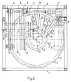
- eine Seitenansicht einer erfindungsgemäßen Einrichtung, in Richtung des Pfeils I in Fig. 2 gesehen;
- Fig. 2
- die Vorderansicht in Richtung des Pfeils II in Fig. 1;
- Fig. 3
- die zu Fig. 1 und 2 gehörige Draufsicht, teilweise als waagrechter Schnitt in der Ebene III-III in Fig. 2 gezeichnet;
- Fig. 4 A und B
- den oberen bzw. unteren Teil des Schnittes in der senkrechten Ebene IV-IV in Fig. 3;
- Fig. 5
- einen Ausschnitt aus der 4 B, vergrößert;
- Fig. 6
- die Ansicht in Richtung des Pfeils VI in Fig. 5;
- Fig. 7
- einen Ausschnitt aus Fig. 5, jedoch in einer Ruhestellung, weiter vergrößert;
- Fig. 8
- den Querschnitt VIII-VIII in Fig. 5, um 90° gedreht und vergrößert;
- Fig. 9
- einen Ausschnitt aus Fig. 8, weiter vergrößert;
- Fig. 10
- den Schnitt in der senkrechten Ebene X-X in Fig. 2, vergrößert;
- Fig. 11
- einen Ausschnitt aus Fig. 10, weiter vergrößert, und
- Fig. 12
- den Schnitt XII-XII in Fig. 11.
- Fig. 1
- a side view of a device according to the invention, seen in the direction of arrow I in Fig. 2;
- Fig. 2
- the front view in the direction of arrow II in Fig. 1;
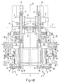
- Fig. 3
- the top view associated with Figures 1 and 2, partially drawn as a horizontal section in the plane III-III in Fig. 2.
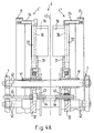
- 4 A and B
- the upper and lower part of the section in the vertical plane IV-IV in Fig. 3;
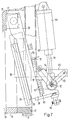
- Fig. 5
- a section of the 4 B, enlarged;
- Fig. 6
- the view in the direction of arrow VI in Fig. 5;
- Fig. 7
- a section of Figure 5, but in a rest position, further enlarged.
- Fig. 8
- the cross section VIII-VIII in Figure 5, rotated by 90 ° and enlarged.
- Fig. 9
- a section of Figure 8, further enlarged;
- Fig. 10
- the section in the vertical plane XX in Figure 2, enlarged.
- Fig. 11
- a section of Fig. 10, further enlarged, and
- Fig. 12
- the section XII-XII in Fig. 11.
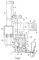
Die dargestellte Einrichtung hat die Aufgabe, mehrblättrige, gefalzte und geheftete Druckerzeugnisse P an ihrem vom Falz abgewandten Rand, der sogenannten Blume, sowie an zwei rechtwinklig zum Falz und zur Blume verlaufenden Seitenrändern zu beschneiden. In einem oberen Bereich eines quaderförmigen Gestells 1 ist ein erstes Zellenrad 2 um eine senkrechte Achse 3 drehbar gelagert. Darunter ist ein zweites Zellenrad 4 um eine waagrechte Achse 5 drehbar gelagert. Die Druckerzeugnisse P werden von einem Zuförderer 6 dem ersten Zellenrad 2 zugeführt, wo sie einzeln an ihrer Blume beschnitten (sogenannter Vorderbeschnitt) werden, dann vom ersten Zellenrad 2 einzeln in das zweite Zellenrad 4 abgeworfen, dort an ihren beiden Seitenrändern beschnitten (sogenannter Kopf-/Fußeschnitt) und schließlich von einem Abförderer 7 einzeln weiterbefördert.The device shown has the task of trimming multi-leaf, folded and stapled printed products P on their edge facing away from the fold, the so-called flower, and on two side edges running at right angles to the fold and the flower. In an upper area of a
Die beiden Zellenräder 2 und 4 sowie die beiden Förderer 6 und 7 werden gemeinsam von einem Motor 8 über ein Getriebe 9 kontinuierlich angetrieben. Zu diesem Zweck erstreckt sich vom Getriebe 9 eine Welle 10 senkrecht nach oben, die mit einem auf ihr angeordneten Antriebsritzel 11 in einen Zahnkranz 12 am äußeren Umfang des ersten Zellenrades 2 eingreift. Ferner erstreckt sich vom Getriebe 9 eine waagerechte Welle 13 zu einem Zahnriementrieb 14, der eine untere waagrechte Welle 15 antreibt; auf dieser sind zwei langgestreckte Antriebsritzel 16 angeordnet, die mit je einem Zahnkranz 17 am äußeren Umfang des zweiten Zellenrades 4 kämmen. Von diesen Zahnkränzen 17 aus werden die beiden Förderer 6 und 7 über je einen Zahnriementrieb 18 bzw. 19 angetrieben.The two
Das erste Zellenrad 2, das sich in Richtung des Pfeils 20 in Fig. 1, 2 und 3 dreht, hat eine Habe 21, die auf einem Lagerkörper 22 axial unverschiebbar gelagert ist und durch dreißig Speichen 23 mit einem zylindrischen Mantel 24 verbunden ist. Dadurch sind dreißig gleiche, nach oben und nach unten offene Zellen 25 gebildet. Die Anzahl der Speichen 23 und Zellen 25 ist nicht entscheidend; sie kann von Fall zu Fall entsprechend dem Bedarf festgelegt werden. Jede der Zellen 25 ist dazu bestimmt, ein Druckerzeugnis mit oben waagerecht liegender Blume aufzunehmen und mit einer Preßvorrichtung, die von bekannter Art sein kann, derart an eine der benachbarten Speichen 23 zu klemmen, daß das Druckerzeugnis P an seiner Blume beschnitten werden kann. Hierzu ist am oberen Rand jeder der Speichen 23 ein waagerechtes Messer 26 so befestigt, daß es mit dem ersten Zellenrad 2 umläuft.The first
Die Messer 26 sind gemäß Fig. 3 rückwärtsgeneigt; jedes von ihnen schließt mit einem von der Achse 3 ausgehenden Radius einen Winkel von ungefähr 20° ein.The
Der Lagerkörper 22 des ersten Zellenrades 2 trägt zwei Messerlager 27, an denen je ein Messerbalken 28 gelagert ist, der ein im Betrieb ortsfestes Gegenmesser 29 trägt. Von den beiden Gegenmessern 29 nimmt jeweils nur eines eine Arbeitsstellung ein, in der es mit den umlaufenden Messern 26 zusammenwirkt. Ist das zuerst benutzte Gegenmesser 29 stumpf geworden, so wird das zweite Gegenmesser 29 durch Schwenken seines Messerbalkens 28 in seine Arbeitsstellung geschwenkt, und das stumpf gewordene Gegenmesser wird samt seinem Messerbalken in eine Ruhestellung geschwenkt.The bearing
Es wird davon abgesehen, die am ersten Zellenrad 2 angeordneten Vorrichtungen zum Pressen der Druckerzeugnisse P sowie zum Führen und Schwenken der Gegenmesser 29 näher darzustellen und zu beschreiben, da insoweit auf entsprechende, im folgenden beschriebene Anordnungen im zweiten Zellenrad 4 verwiesen werden kann.It is not shown and described in more detail the devices arranged on the
Das zweite Zellenrad 4, das sich in Richtung des Pfeils 30 in Fig. 1 dreht, ist aus zwei Zellenradhälften 4' und 4'' zusammengesetzt. Jede Zellenradhälfte 4', 4'' hat eine Habe 31, die auf einem Lagerkörper 32 gelagert und durch dreißig Speichen 33 mit einem zylindrischen Mantel 34 und über diesen mit je einem der erwähnten Zahnkränze 17 verbunden ist. Auf diese Weise bilden die beiden Zellenradhälften gemeinsam dreißig Zellen 35, von denen sich jede zwischen zwei im axialen Abstand parallel zueinander angeordneten Speichen 33 erstreckt. Auch hier ist die Anzahl der Zellen 35 nicht entscheidend; sie stimmt vorzugsweise, jedoch nicht unbedingt, mit der Anzahl der Zellen 25 im ersten Zellenrad 2 überein. An jeder Speiche 33 ist ein Messer 36 befestigt, das unter einem Winkel von beispielsweise 20° gegen die Radialrichtung nach hinten geneigt ist.The
Jede der beiden Naben 31 trägt zwei Messerlager 37, an denen je ein Messerbalken 38 mit einem Gegenmesser 39 schwenkbar und in einer zur Drehachse 5 parallelen Richtung einstellbar gelagert ist. Jeder der beiden Hälften 4' und 4'' des zweiten Zellenrades 4 sind somit zwei Gegenmesser 39 zugeordnet, von denen jedoch jeweils nur eines seine Arbeitsstellung einnimmt, in der es mit den umlaufenden Messern 36 an der zugehörigen Zellenradhälfte zusammenwirkt, während das andere Gegenmesser in Reserve bleibt. Jedes Gegenmesser 39 hat gemäß Fig. 6 eine dachgiebelförmige Schneide.Each of the two
Die gesamte Anordnung des zweiten Zellenrades 4 mit seinen beiden Hälften 4' und 4'' und den zugehörigen Gegenmessern 39 ist symmetrisch in Bezug auf eine senkrechte, also zur Drehachse 5 normale, Symmetrieebene 40. Dieses gilt für jede Betriebseinstellung des zweiten Zellenrades 4.The entire arrangement of the second
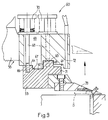
Die beiden Lagerkörper 32 für das zweite Zellenrad 4 sind mit je drei an ihnen ausgebildeten Gleitbüchsen 41 an insgesamt drei Führungsstangen 42 geführt, die parallel zur waagerechten Achse 5 in gleichen Abständen von dieser angeordnet und mit ihren Enden im Gestell 1 befestigt sind. An jeder der beiden Naben 31 ist außerdem eine zentrale Gewindebüchse 43 befestigt. Mit diesen Gewindebüchsen 43, von denen eine rechts- und die andere linksgängig ist, und die beide dem Betrag nach gleiche Steigungen haben, steht je ein entsprechender Gewindeschnitt 44 auf einer gemeinsamen Spindel 45 in Eingriff. Die Spindel 45 erstreckt sich längs der waagerechten Achse 5 und ist im Gestell 1 axial unverschiebbar gelagert. Durch Drehen der Spindel 45 in der einen oder anderen Richtung lassen sich die beiden Lagerkörper 32, und somit die beiden Hälften 4' und 4'' des zweiten Zellenrades 4, entsprechend dem Format der zu beschneidenden Druckerzeugnisse P zueinander hin oder voneinander weg verstellen. Zum Drehen der Spindel 45 kann ein Handrad oder auch ein beispielsweise elektrischer Servomotor vorgesehen sein.The two bearing
Jeder der beiden Messerbalken 38 trägt an seinem vom zugehörigen Messerlager 37 entfernten freien Ende ein Führungsglied 46, im dargestellten Beispiel eine exzentrisch, also einstellbar, am Messerbalken 38 frei drehbar gelagerte Laufrolle. Das Führungsglied 46 läuft in Betriebsstellung des zugehörigen Messerbalkens 38 auf einer ebenen ringförmigen Lauffläche 47 am Zahnkranz 17 der zugehörigen Hälfte des zweiten Zellenrades 4. Auf diese Weise wird gewährleistet, daß jedes der ortsfesten Gegenmesser 39 in seiner Betriebsstellung mit den zugehörigen umlaufenden Messern 36 einen genau einstellbaren und gleichbleibenden Schneidspalts bildet.Each of the two
Zum Andrücken des Führungsgliedes 46 an die zugehörige Lauffläche 47 sowie zum Schwenken aus der Betriebsstellung gemäß Fig. 4 B bis 6 in eine Ruhestellung gemäß Fig. 7 ist jedem Messerbalken 38 eine Anpreß- und Schwenkvorrichtung zugeordnet, die einen am zugehörigen Lagerkörper 32 befestigten, ungefähr radialen Stützbalken 48 und einen von diesem parallel zur waagerechten Achse 5 wegragenden Ausleger 49 aufweist. Am Stützbalken 48 ist ein hydraulischer oder pneumatischer Zylinder 50 gelagert, dessen Kolbenstange ein Stellglied 51 bildet und durch eine Gelenk 52 mit einem Lenker 53 und einem Koppelglied 54 verbunden ist. Der Lenker 53 ist mit seinem vom Gelenk 52 abgewandten Ende am Ausleger 49 gelagert und bildet zusammen mit dem Koppelglied 54 einen Kniehebel. Das Koppelglied 54 setzt sich zusammen aus einem am Gelenk 52 gelagerten Gehäuse 55, in dem ein Stößel 56 verschiebbar geführt und durch eine Federanordnung 57 in axialer Richtung vorgespannt ist. Der Stößel 56 ist gelenkig mit dem zugehörigen Messerbalken 38 verbunden.For pressing the
In Betriebsstellung des Gegenmessers 39 ist die das Stellglied 51 bildende Kolbenstange eingefahren. Dabei nimmt der vom Lenker 53 und Koppelglied 54 gebildete Kniehebel eine etwas mehr als gestreckte Übertotpunktstellung ein. Die Kraft, mit der die Laufrolle 46 an die Lauffläche 47 angepreßt wird, ist durch die Vorspannung der Federanordnung 57 bestimmt. Die im Betrieb auf das Gegenmesser 39 einwirkenden Schneidkräfte werden vom Messerbalken 38 auf einen ortsfesten Stützkörper 58 übertragen, der aus Kunststoff mit guten Gleiteigenschaften besteht. Soll das betreffende Gegenmesser 39 von der zugehörigen Zellenradhälfte des zweiten Zellenrades 4 weggeschwenkt werden, so wird das Stellglied 51 ausgefahren, so daß der Kniehebel 53, 54 gemäß Fig. 7 eine abgewinkelte Stellung einnimmt.In the operating position of the
Gemäß Fig. 8 und 9 ist jedes der Gegenmesser 39 an einer Halterung 59 befestigt, die durch eine Überlastsicherung 60 mit dem zugehörigen Messerbalken 38 verbunden ist. Zur Überlastsicherung 60 gehören ein vorderer Sitz 61 und ein hinterer Sitz 62 am Messerbalken 38 sowie eine zwischen diesen Sitzen 61 und 62 ausgebildete Vertiefung 63 und eine hinter dem hinteren Sitz 62 ausgebildete Vertiefung 64 im Messerbalken 38. An den Sitzen 61 und 62 liegt normalerweise je ein Vorsprung 65 bzw. 66 an, die an der Halterung 59 ausgebildet und durch eine Vertiefung 67 voneinander getrennt sind. In die Halterung 59 sind mehrere Zuganker 68 eingeschraubt, die sich durch je ein Langloch 69 im Messerbalken 38 hindurcherstrecken und an dessen von der Halterung 59 abgewandten Seite durch je eine Federanordnung 70 vorgespannt sind. Im dargestellten Beispiel sind die Federanordnungen 70 von je einem Tellerfederpaket gebildet, wie vor allem aus Fig. 9 ersichtlich ist. Die Halterung 59 hat außerdem einen vorderen Ansatz 71, der mit am zugehörigen Messerbalken 38 befestigten Sensoren 72 zusammenwirkt.8 and 9, each of the
Bei Überlastung eines Gegenmessers 39 verschiebt sich die zugehörige Halterung 59 aus ihrer in Fig. 8 abgebildeten normalen Stellung in die in Fig. 9 abgebildete Stellung. Dabei gleiten die beiden Vorsprünge 65 und 66 von ihren Sitzen 61 und 62 nach hinten und werden von den vorgespannten Zugankern 68 in je eine der beiden Vertiefungen 63 und 64 hineingezogen, wodurch einerseits der normale Schneidspalt S (Fig. 8) um ein Vielfaches vergrößert wird (Fig. 9) und andererseits eine weitere Verschiebung der Halterung 59 gegenüber dem zugehörigen Messerbalken 38 verhindert wird. Ferner verschwindet der Ansatz 71 aus dem Überwachungsbereich der zugehörigen Sensoren 72, so daß diese ein Signal abgeben, das als Notsignal gewertet und dazu benutzt wird, den zugehörigen Zylinder 50 umzusteuern, so daß das Stellglied 51 ausgefahren und dadurch der betreffende Messerbalken 38 in seine Ruhestellung gemäß Fig. 7 geschwenkt wird.If a
An jedem der Messerbalken 38 ist ferner ein Mundstück 73 einer Anlage zum Absaugen abgeschnittener Papierstreifen befestigt. Das Mundstück 73 ist ein in radialer Richtung des zweiten Zellenrades 4 langgestreckter Kasten, der zum zugehörigen Gegenmesser 39 hin offen ist und in seinem radial inneren Endbereich an eine Saugleitung 74 angeschlossen ist.On each of the cutter bars 38, a
Die radiale Tiefe jeder der Zellen 35 des zweiten Zellenrades 4 ist durch eine zu dessen Achse 5 parallele Anschlagleiste 75 begrenzt. Sämtliche Anschlagleisten 75 sind in gleichem Abstand von der Achse 5 derart angeordnet, daß die Druckerzeugnisse P zum Beschneiden ihrer seitlichen Ränder gerade tief genug in je eine der Zellen 35 eingeführt werden können. Die Länge der umlaufenden Messer 36 und der Gegenmesser 39 ist so bemessen, daß Druckerzeugnisse P unterschiedlicher Höhe - gemessen als Abstand zwischen Falz und Blume - in gleicher Weise seitlich beschnitten werden können.The radial depth of each of the
Damit die in je eine der Zellen 35 eingeführten Druckerzeugnisse P flach liegen und nicht durchhängen, ist an jeder der Speichen 33 ein Wandabschnitt 76 befestigt. Wenn die beiden Zellenradhälften 4' und 4'' des zweiten Zellenrades 4 zum Beschneiden großformatiger Druckerzeugnisse eingestellt sind und somit einen großen Abstand voneinander haben, beispielsweise wie in Fig. 4 A dargestellt, kann zwischen zusammengehörigen Wandabschnitten 76 ein kleiner Zwischenraum freibleiben, was unschädlich ist. Wenn die beiden Zellenradhälften 4' und 4'' für das Beschneiden von Druckerzeugnissen kleineren Formats einander genähert werden, schieben sich die Wandabschnitte 76 teleskopartig übereinander.So that the printed products P inserted into one of the
Jede der Zellen 35 enthält ein Paar Preßleisten 77, die parallel und in Nachbarschaft zu je einem der zugehörigen umlaufenden Messer 36 derart angeordnet sind, daß das in die betreffende Zelle eingeführte Druckerzeugnis P längs seiner beiden Ränder, die beschnitten werden sollen, zwischen je einer der Preßleisten 77 und dem benachbarten Messer 36 festgeklemmt wird, ehe mit dem Beschneiden begonnen wird. Jede der Preßleisten 77 ist gemäß Fig. 10 bis 12 mittels eines Gelenks 78 an einem Lenker 79 gelagert, der seinerseits mittels eines Lagers 80 an einem zweiarmigen Hebel 81 gelagert ist. Der zweiarmige Hebel 81 ist mittels eines Lagers 82 an der benachbarten Speiche 33 gelagert. Die geometrischen Achsen der Lager 80 und 82 sind ebenso wie die Achse des Gelenks 78 parallel zur Achse 5 des zweiten Zellenrades 4. Der Lenker 79 hat einen im wesentlichen radial nach außen ragenden Fortsatz 83; zwischen diesem und der Preßleiste 77 ist eine Feder 84 eingespannt, die im dargestellten Beispiel eine schraubenförmige Druckfeder ist.Each of the
Der Schwenkbereich des zweiarmigen Hebels 81 ist durch einen Zuganker 85 begrenzt. Durch eine Feder 86 - dargestellt ist eine schraubenförmige Druckfeder, durch die sich der Zuganker 85 hindurcherstreckt - ist der zweiarmige Hebel 81 derart vorgespannt, daß er bestrebt ist, die mit ihm verbundene Preßleiste 77 von der vor ihr - in Fig. 11 rechts von ihr - angeordneten Speiche 33 wegzuziehen. In gleichem Sinne wirkt eine Feder 87, die zwischen dem Lenker 79 und der vor ihm liegenden Speiche 33 eingespannt ist. Die Schwenkung des Lenkers 79 wird durch einen einstellbaren Anschlag 88 an der hinter ihm - in Fig. 11 links von ihm - angeordneten Speiche 33 begrenzt. An dem vom Lenker 79 entfernten Ende des zweiarmigen Hebels 81 ist eine Rolle 89 gelagert, die durch den Druck der Feder 86 an einer Steuerkurve 90 am zugehörigen Lagerkörper 32 anliegend gehalten wird. Auf diese Weise lassen sich die Druckerzeugnisse P, ihrer Dicke angepaßt, in einer vorbestimmten Lage in der sie aufnehmenden Zelle 35 sicher festpressen.The swivel range of the two-
Die beschriebene Einrichtung arbeitet folgendermaßen:
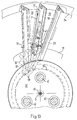
Unbeschnittene Druckerzeugnisse P werden vom Förderer 6 mit ihrem Falz nach unten hängend herangeschafft und in je eine Zelle 25 des ersten Zellenrades 2 fallengelassen. Der Fall wird begrenzt von einer Abstützung 91 in Gestalt bogenförmiger Leisten, die in einem Zuführbereich unterhalb des ersten Zellenrades 2 höheneinstellbar am Gestell 1 befestigt sind. Beim Weiterdrehen des ersten Zellenrades 2 wird jedes der Druckerzeugnisse in seiner Zelle 25 festgeklemmt und dann an seiner Blume beschnitten und anschließend wieder freigegeben, so daß das Druckerzeugnis etwas weiter nach unten rutscht, bis es mit seinem Falz auf einer unter dem ersten Zellenrad 2 angeordneten bogenförmigen Schiene 92 aufliegt. Die Schiene 92 ist zur Anpassung an unterschiedliche Druckerzeugnisse ebenfalls höheneinstellbar und außerdem in Umfangsrichtung einstellbar am Gestell 1 befestigt. Das Ende der Schiene 92 ist nach unten gebogen. Sobald ein Druckerzeugnis P diese Ende erreicht hat, fällt es aus seiner Zelle 25 in eine sich im selben Augenblick darunter vorbeibewegenden Zelle 35 des zweiten Zellenrades 4.The described device works as follows:
Untrimmed printed products P are brought in by the
In der Zelle 35 wird das Druckerzeugnis P mittels der beiden Preßleisten 77 festgeklemmt und anschließend an seinen beiden seitlichen Rändern beschnitten. Die Preßleisten 77 sind von den Steuerkurven 90 derart gesteuert, daß sie das nun fertig beschnittene Druckerzeugnis P wieder freigeben, so daß dieses nun unter dem Einfluß der Schwerkraft in einem unteren Bereich des zweiten Zellenrades 4 teilweise aus der Zelle 35 herausrutscht, bis die Blume des Druckerzeugnisses gegen eine dort angeordnete bogenförmige Abstützung 93 stößt. Diese Abstützung 93 endet in Fig. 1 rechts vom zweiten Zellenrad 4 in einem Bereich etwas unterhalb von dessen Achse 5, wo das Druckerzeugnis P nicht mehr von alleine weiter aus der Zelle 35 herausrutschen kann. Das Druckerzeugnis P ragt nun aber so weit radial über die Wandabschnitte 76 hinaus, daß es von einem Greifer 94 des Abförderers 7 erfaßt und weitertransportiert werden kann.The printed product P is clamped in the
Claims (10)
daß
that
dadurch gekennzeichnet,
daß die beiden Lagerkörper (32) auf mindestens zwei zur zentralen Achse (5) parallelen Führungsstangen (42) verschiebbar geführt sind.Device according to claim 1,
characterized,
that the two bearing bodies (32) are displaceably guided on at least two guide rods (42) parallel to the central axis (5).
dadurch gekennzeichnet,
daß die beiden Lagerkörper (32) je eine Gewindebuchse (43) aufweisen, in die ein Gewindeabschnitt (44) einer zur zentralen Achse (5) parallelen Spindel (45) eingreift.Device according to claim 1 or 2,
characterized,
that the two bearing bodies (32) each have a threaded bush (43) into which a threaded portion (44) of a spindle (45) parallel to the central axis (5) engages.
dadurch gekennzeichnet,
daß das Zellenrad (4) zwei Zahnkränze (17) aufweist, die zu je einer Zellenradhälfte gehören und mit je einem von zwei auf einer gemeinsamen Welle (15) angeordneten Antriebsritzeln (16) kämmen.Device according to one of claims 1 to 3,
characterized,
that the cellular wheel (4) has two sprockets (17) which each belong to a cellular wheel half and mesh with one of two drive pinions (16) arranged on a common shaft (15).
dadurch gekennzeichnet,
daß jedes Gegenmesser (39) an einem Messerbalken (38) befestigt ist, der über ein Messerlager (37) am zugehörigen Lagerkörper (32) gelagert und an einer Lauffläche (47) der zugehörigen Zellenradhälfte geführt ist.Device according to one of claims 1 to 4,
characterized,
that each counter knife (39) is attached to a knife bar (38) which is mounted on a knife bearing (37) on the associated bearing body (32) and is guided on a running surface (47) of the associated cellular wheel half.
dadurch gekennzeichnet,
daß
characterized,
that
dadurch gekennzeichnet,
daß an jedem Messerbalken (38) ein langgestrecktes Mundstück (73) angeordnet ist, das an eine Saugleitung (74) angeschlossen ist, sich längs des zugehörigen Gegenmessers (39) erstreckt und zu diesem hin offen ist.Device according to claim 5 or 6
characterized,
that an elongated mouthpiece (73) is arranged on each knife bar (38), which is connected to a suction line (74), extends along the associated counter knife (39) and is open towards the latter.
dadurch gekennzeichnet,
daß die Messer (36) und Gegenmesser (39) derart angeordnet sind, daß sie am Produkt (P) einen radial innen beginnenden ziehenden Schnitt ausführen.Device according to one of claims 1 to 7,
characterized,
that the knives (36) and counter-knives (39) are arranged in such a way that they make a drawing cut starting radially on the inside of the product (P).
dadurch gekennzeichnet,
daß jede der Saugleitungen (74) an einen radial inneren Endbereich des zugehörigen Mundstücks (73) angeschlossen ist.Device according to claim 8 in conjunction with claim 7,
characterized,
that each of the suction lines (74) is connected to a radially inner end region of the associated mouthpiece (73).
dadurch gekennzeichnet,
daß
characterized,
that
Applications Claiming Priority (2)
| Application Number | Priority Date | Filing Date | Title |
|---|---|---|---|
| DE4243060A DE4243060C2 (en) | 1992-12-18 | 1992-12-18 | Device for trimming flat products, in particular multi-sheet printed products |
| DE4243060 | 1992-12-18 |
Publications (2)
| Publication Number | Publication Date |
|---|---|
| EP0602594A1 true EP0602594A1 (en) | 1994-06-22 |
| EP0602594B1 EP0602594B1 (en) | 1995-12-06 |
Family
ID=6475827
Family Applications (1)
| Application Number | Title | Priority Date | Filing Date |
|---|---|---|---|
| EP93120130A Expired - Lifetime EP0602594B1 (en) | 1992-12-18 | 1993-12-14 | Device for trimming a flat product, particularly a multi-layer printed product |
Country Status (11)
| Country | Link |
|---|---|
| US (1) | US5501127A (en) |
| EP (1) | EP0602594B1 (en) |
| JP (1) | JP3360151B2 (en) |
| AT (1) | ATE131099T1 (en) |
| AU (1) | AU664931B2 (en) |
| CA (1) | CA2111717C (en) |
| DE (2) | DE4243060C2 (en) |
| ES (1) | ES2080574T3 (en) |
| FI (1) | FI102154B1 (en) |
| RU (1) | RU2121915C1 (en) |
| UA (1) | UA27761C2 (en) |
Cited By (4)
| Publication number | Priority date | Publication date | Assignee | Title |
|---|---|---|---|---|
| CH685153A5 (en) * | 1993-11-17 | 1995-04-13 | Grapha Holding Ag | Method for cutting off at least partly open sides from printing products fed regularly spaced apart |
| EP0753386A1 (en) * | 1995-07-11 | 1997-01-15 | Ferag AG | Apparatus for cutting folded printed products, such as newspapers, magazines, brochures or the like |
| CH690296A5 (en) * | 1995-09-27 | 2000-07-14 | Ferag Ag | Device for cutting continuously fed print products or print product groups between counter blade and cutting blade involves conveyor feeding products in direction parallel or crossways to predetermined cut line |
| EP1661833A1 (en) | 2004-11-26 | 2006-05-31 | Ferag AG | Method and device for treating printed products |
Families Citing this family (9)
| Publication number | Priority date | Publication date | Assignee | Title |
|---|---|---|---|---|
| DE59600953D1 (en) * | 1995-05-02 | 1999-01-21 | Grapha Holding Ag | METHOD AND DEVICE FOR HANDLING PRINTED PRODUCTS |
| CH690323A5 (en) * | 1995-10-04 | 2000-07-31 | Ferag Ag | Method and apparatus for cutting continuously demanded, in particular of paper products flochigen. |
| US5992284A (en) * | 1997-11-17 | 1999-11-30 | Urschel Laboratories Incorporated | Knife and cutting wheel for a food product slicing apparatus |
| US6792841B2 (en) | 1999-12-08 | 2004-09-21 | Urschel Laboratories Incorporated | Transverse food product slicer with inclined shear edge support surface enabling production of uniform thickness slices |
| EP1563968B1 (en) | 2004-02-17 | 2010-07-28 | Müller Martini Holding AG | A system for the trimming a printed product along the bloom edge and along each of the opposite side edges of the product |
| DE102004029170B4 (en) * | 2004-06-16 | 2007-05-03 | Man Roland Druckmaschinen Ag | Jib module for a printing machine |
| CH704642B1 (en) * | 2005-01-21 | 2012-09-28 | Ferag Ag | Apparatus for trimming of flexible, flat products. |
| EP1881010B1 (en) * | 2006-05-31 | 2010-08-11 | 3M Innovative Properties Company | Polymerizable compositions containing salts of barbituric acid derivatives |
| CA2657075A1 (en) * | 2008-03-17 | 2009-09-17 | Ferag Ag | Device and method for trimming folded printed products |
Citations (4)
| Publication number | Priority date | Publication date | Assignee | Title |
|---|---|---|---|---|
| US2745233A (en) * | 1951-03-10 | 1956-05-15 | Dow Corning | Semiautomatic book-forming machine and method |
| DE2237731A1 (en) * | 1971-08-19 | 1973-03-01 | Polygraph Leipzig | CUTTING PRODUCT FEEDING DEVICE FOR THREE KNIFE CUTTING MACHINES |
| FR2306800A1 (en) * | 1975-04-08 | 1976-11-05 | Ferag Ag | DEVICE FOR CUTTING SHEET PRODUCTS CONTINUOUSLY ARRIVING |
| EP0367715A1 (en) * | 1988-10-31 | 1990-05-09 | Ferag AG | Method and device for trimming printed produce |
Family Cites Families (10)
| Publication number | Priority date | Publication date | Assignee | Title |
|---|---|---|---|---|
| US1232776A (en) * | 1916-08-17 | 1917-07-10 | Internat Press Company | Paper and card gathering and jogging device. |
| US2245868A (en) * | 1938-09-10 | 1941-06-17 | Charles J Melby | Automatic edge-trimming machine |
| US2617461A (en) * | 1951-04-03 | 1952-11-11 | Gerda F Bach | Mushroom decapping, trimming, and cutting machine |
| US4496140A (en) * | 1983-09-19 | 1985-01-29 | Stobb, Inc. | Apparatus for handling a signature |
| DE3443032C1 (en) * | 1984-11-26 | 1986-04-30 | H. Putsch Gmbh & Co, 5800 Hagen | Cutting disc machine, in particular for cutting sugar beet |
| JPS61188350A (en) * | 1985-02-13 | 1986-08-22 | Oki Electric Ind Co Ltd | Front and back reversing mechanism |
| CH668244A5 (en) * | 1985-10-23 | 1988-12-15 | Ferag Ag | METHOD AND DEVICE FOR PROCESSING PRINTED PRODUCTS. |
| US5046711A (en) * | 1988-01-29 | 1991-09-10 | Hall Processing Systems | High speed drum type processing apparatus |
| JPH06104523B2 (en) * | 1989-05-11 | 1994-12-21 | 株式会社東京機械製作所 | Folding device impeller |
| US5011132A (en) * | 1990-05-29 | 1991-04-30 | Peter Guttinger | Load accumulator having positive drive conveyor |
-
1992
- 1992-12-18 DE DE4243060A patent/DE4243060C2/en not_active Expired - Fee Related
-
1993
- 1993-12-14 ES ES93120130T patent/ES2080574T3/en not_active Expired - Lifetime
- 1993-12-14 AT AT93120130T patent/ATE131099T1/en not_active IP Right Cessation
- 1993-12-14 EP EP93120130A patent/EP0602594B1/en not_active Expired - Lifetime
- 1993-12-14 DE DE59301107T patent/DE59301107D1/en not_active Expired - Lifetime
- 1993-12-16 AU AU52519/93A patent/AU664931B2/en not_active Ceased
- 1993-12-17 UA UA93003752A patent/UA27761C2/en unknown
- 1993-12-17 CA CA002111717A patent/CA2111717C/en not_active Expired - Fee Related
- 1993-12-17 US US08/168,415 patent/US5501127A/en not_active Expired - Lifetime
- 1993-12-17 RU RU93056624A patent/RU2121915C1/en not_active IP Right Cessation
- 1993-12-17 FI FI935714A patent/FI102154B1/en active
- 1993-12-20 JP JP34481493A patent/JP3360151B2/en not_active Expired - Fee Related
Patent Citations (4)
| Publication number | Priority date | Publication date | Assignee | Title |
|---|---|---|---|---|
| US2745233A (en) * | 1951-03-10 | 1956-05-15 | Dow Corning | Semiautomatic book-forming machine and method |
| DE2237731A1 (en) * | 1971-08-19 | 1973-03-01 | Polygraph Leipzig | CUTTING PRODUCT FEEDING DEVICE FOR THREE KNIFE CUTTING MACHINES |
| FR2306800A1 (en) * | 1975-04-08 | 1976-11-05 | Ferag Ag | DEVICE FOR CUTTING SHEET PRODUCTS CONTINUOUSLY ARRIVING |
| EP0367715A1 (en) * | 1988-10-31 | 1990-05-09 | Ferag AG | Method and device for trimming printed produce |
Cited By (5)
| Publication number | Priority date | Publication date | Assignee | Title |
|---|---|---|---|---|
| CH685153A5 (en) * | 1993-11-17 | 1995-04-13 | Grapha Holding Ag | Method for cutting off at least partly open sides from printing products fed regularly spaced apart |
| EP0753386A1 (en) * | 1995-07-11 | 1997-01-15 | Ferag AG | Apparatus for cutting folded printed products, such as newspapers, magazines, brochures or the like |
| AU699259B2 (en) * | 1995-07-11 | 1998-11-26 | Ferag Ag | Apparatus for trimming folded printed products, such as newspapers, periodicals, brochures and the like |
| CH690296A5 (en) * | 1995-09-27 | 2000-07-14 | Ferag Ag | Device for cutting continuously fed print products or print product groups between counter blade and cutting blade involves conveyor feeding products in direction parallel or crossways to predetermined cut line |
| EP1661833A1 (en) | 2004-11-26 | 2006-05-31 | Ferag AG | Method and device for treating printed products |
Also Published As
| Publication number | Publication date |
|---|---|
| ES2080574T3 (en) | 1996-02-01 |
| DE4243060A1 (en) | 1994-06-23 |
| DE59301107D1 (en) | 1996-01-18 |
| FI935714A (en) | 1994-06-19 |
| EP0602594B1 (en) | 1995-12-06 |
| AU664931B2 (en) | 1995-12-07 |
| UA27761C2 (en) | 2000-10-16 |
| CA2111717C (en) | 2004-07-20 |
| AU5251993A (en) | 1994-06-30 |
| FI102154B (en) | 1998-10-30 |
| FI935714A0 (en) | 1993-12-17 |
| JP3360151B2 (en) | 2002-12-24 |
| CA2111717A1 (en) | 1994-06-19 |
| JPH071387A (en) | 1995-01-06 |
| RU2121915C1 (en) | 1998-11-20 |
| FI102154B1 (en) | 1998-10-30 |
| ATE131099T1 (en) | 1995-12-15 |
| DE4243060C2 (en) | 1994-09-15 |
| US5501127A (en) | 1996-03-26 |
Similar Documents
| Publication | Publication Date | Title |
|---|---|---|
| EP0602594B1 (en) | Device for trimming a flat product, particularly a multi-layer printed product | |
| EP0602593B1 (en) | Device for trimming a flat product, particularly a multi-layer printed product | |
| DE2401340C3 (en) | Wrapping device in a coin wrapping machine | |
| DE3123183C2 (en) | ||
| CH689449A5 (en) | Cutting process for flat print products along preset cutting line | |
| DE69814853T2 (en) | Method and device for moving the circular knife of a machine for cutting paper rolls or the like | |
| DE1561716B1 (en) | Paper cutting machine with a cross cutter | |
| EP1260325B1 (en) | Three-side trimming machine | |
| DE102007030977A1 (en) | Cutting device for cutting a strip has a roller to rotate on a central swivel pin, a moving knife attached to the roller and fixed knife near the roller | |
| EP2279145B1 (en) | Folding device comprising upstream or downstream blade shafts or comparable tool shafts | |
| EP1156004B1 (en) | Folding apparatus | |
| DE2715794A1 (en) | CUTTING MACHINE | |
| DE2039844B1 (en) | DEVICE FOR CUTTING PAPER TRAILS FOR THE FOLDER OF A ROTARY PRINTING MACHINE | |
| WO2018071950A1 (en) | Device for cutting partial strips of predeterminable width | |
| DE2117311C3 (en) | Device for pulling sheets of paper from a stack | |
| CH713149A1 (en) | Method and device for transporting variable-thickness printed products. | |
| EP0774300A1 (en) | Compacting and treating device | |
| EP0832734B1 (en) | Method and apparatus for producing transverse precreases, in particular on envelope blanks | |
| EP0753386A1 (en) | Apparatus for cutting folded printed products, such as newspapers, magazines, brochures or the like | |
| DE2243504C2 (en) | Device for the continuous winding of a film web onto winding tubes | |
| DE583190C (en) | Machine for cutting a continuously guided tube made of paper | |
| DE411108C (en) | Rotary printing machine for producing cards from paper webs or the like. | |
| DE2534753A1 (en) | CARDBOARD MAKING MACHINE | |
| DE1511272C (en) | Cutting device for cross-cutting webs of foil material, for example paper | |
| DE2310944A1 (en) | METHOD AND APPARATUS FOR THE OPTIONAL MANUFACTURING OF WIDE-END OR TIP-END LETTERHOLDER FROM A PAPER WEB PULLED FROM A ROLL |
Legal Events
| Date | Code | Title | Description |
|---|---|---|---|
| PUAI | Public reference made under article 153(3) epc to a published international application that has entered the european phase |
Free format text: ORIGINAL CODE: 0009012 |
|
| AK | Designated contracting states |
Kind code of ref document: A1 Designated state(s): AT BE CH DE ES FR GB IT LI NL SE |
|
| 17P | Request for examination filed |
Effective date: 19940606 |
|
| 17Q | First examination report despatched |
Effective date: 19950505 |
|
| GRAA | (expected) grant |
Free format text: ORIGINAL CODE: 0009210 |
|
| AK | Designated contracting states |
Kind code of ref document: B1 Designated state(s): AT BE CH DE ES FR GB IT LI NL SE |
|
| REF | Corresponds to: |
Ref document number: 131099 Country of ref document: AT Date of ref document: 19951215 Kind code of ref document: T |
|
| REF | Corresponds to: |
Ref document number: 59301107 Country of ref document: DE Date of ref document: 19960118 |
|
| REG | Reference to a national code |
Ref country code: ES Ref legal event code: FG2A Ref document number: 2080574 Country of ref document: ES Kind code of ref document: T3 |
|
| ITF | It: translation for a ep patent filed |
Owner name: SOCIETA' ITALIANA BREVETTI S.P.A. |
|
| REG | Reference to a national code |
Ref country code: CH Ref legal event code: NV Representative=s name: SCHAAD, BALASS & PARTNER AG |
|
| ET | Fr: translation filed | ||
| GBT | Gb: translation of ep patent filed (gb section 77(6)(a)/1977) |
Effective date: 19960305 |
|
| PLBE | No opposition filed within time limit |
Free format text: ORIGINAL CODE: 0009261 |
|
| STAA | Information on the status of an ep patent application or granted ep patent |
Free format text: STATUS: NO OPPOSITION FILED WITHIN TIME LIMIT |
|
| 26N | No opposition filed | ||
| REG | Reference to a national code |
Ref country code: GB Ref legal event code: IF02 |
|
| PGFP | Annual fee paid to national office [announced via postgrant information from national office to epo] |
Ref country code: NL Payment date: 20021130 Year of fee payment: 10 |
|
| PGFP | Annual fee paid to national office [announced via postgrant information from national office to epo] |
Ref country code: AT Payment date: 20021204 Year of fee payment: 10 |
|
| PGFP | Annual fee paid to national office [announced via postgrant information from national office to epo] |
Ref country code: BE Payment date: 20021205 Year of fee payment: 10 |
|
| PG25 | Lapsed in a contracting state [announced via postgrant information from national office to epo] |
Ref country code: AT Free format text: LAPSE BECAUSE OF NON-PAYMENT OF DUE FEES Effective date: 20031214 |
|
| PG25 | Lapsed in a contracting state [announced via postgrant information from national office to epo] |
Ref country code: BE Free format text: LAPSE BECAUSE OF NON-PAYMENT OF DUE FEES Effective date: 20031231 |
|
| BERE | Be: lapsed |
Owner name: *FERAG A.G. Effective date: 20031231 |
|
| PG25 | Lapsed in a contracting state [announced via postgrant information from national office to epo] |
Ref country code: NL Free format text: LAPSE BECAUSE OF NON-PAYMENT OF DUE FEES Effective date: 20040701 |
|
| NLV4 | Nl: lapsed or anulled due to non-payment of the annual fee |
Effective date: 20040701 |
|
| REG | Reference to a national code |
Ref country code: CH Ref legal event code: PFA Owner name: FERAG AG Free format text: FERAG AG#ZUERICHSTRASSE 74#CH-8340 HINWIL (CH) -TRANSFER TO- FERAG AG#PATENTABTEILUNG Z. H. MARKUS FELIX ZUERICHSTRASSE 74#8340 HINWIL (CH) |
|
| PGFP | Annual fee paid to national office [announced via postgrant information from national office to epo] |
Ref country code: ES Payment date: 20081217 Year of fee payment: 16 |
|
| PGFP | Annual fee paid to national office [announced via postgrant information from national office to epo] |
Ref country code: IT Payment date: 20081223 Year of fee payment: 16 |
|
| PGFP | Annual fee paid to national office [announced via postgrant information from national office to epo] |
Ref country code: FR Payment date: 20081212 Year of fee payment: 16 |
|
| PGFP | Annual fee paid to national office [announced via postgrant information from national office to epo] |
Ref country code: GB Payment date: 20081216 Year of fee payment: 16 |
|
| GBPC | Gb: european patent ceased through non-payment of renewal fee |
Effective date: 20091214 |
|
| REG | Reference to a national code |
Ref country code: FR Ref legal event code: ST Effective date: 20100831 |
|
| PG25 | Lapsed in a contracting state [announced via postgrant information from national office to epo] |
Ref country code: FR Free format text: LAPSE BECAUSE OF NON-PAYMENT OF DUE FEES Effective date: 20091231 |
|
| PG25 | Lapsed in a contracting state [announced via postgrant information from national office to epo] |
Ref country code: GB Free format text: LAPSE BECAUSE OF NON-PAYMENT OF DUE FEES Effective date: 20091214 |
|
| REG | Reference to a national code |
Ref country code: ES Ref legal event code: FD2A Effective date: 20110325 |
|
| PG25 | Lapsed in a contracting state [announced via postgrant information from national office to epo] |
Ref country code: IT Free format text: LAPSE BECAUSE OF NON-PAYMENT OF DUE FEES Effective date: 20091214 |
|
| PG25 | Lapsed in a contracting state [announced via postgrant information from national office to epo] |
Ref country code: ES Free format text: LAPSE BECAUSE OF NON-PAYMENT OF DUE FEES Effective date: 20110314 |
|
| PG25 | Lapsed in a contracting state [announced via postgrant information from national office to epo] |
Ref country code: ES Free format text: LAPSE BECAUSE OF NON-PAYMENT OF DUE FEES Effective date: 20091215 |
|
| PGFP | Annual fee paid to national office [announced via postgrant information from national office to epo] |
Ref country code: CH Payment date: 20121205 Year of fee payment: 20 |
|
| PGFP | Annual fee paid to national office [announced via postgrant information from national office to epo] |
Ref country code: SE Payment date: 20121220 Year of fee payment: 20 |
|
| PGFP | Annual fee paid to national office [announced via postgrant information from national office to epo] |
Ref country code: DE Payment date: 20121220 Year of fee payment: 20 |
|
| REG | Reference to a national code |
Ref country code: DE Ref legal event code: R071 Ref document number: 59301107 Country of ref document: DE |
|
| REG | Reference to a national code |
Ref country code: DE Ref legal event code: R071 Ref document number: 59301107 Country of ref document: DE |
|
| REG | Reference to a national code |
Ref country code: CH Ref legal event code: PL |
|
| PG25 | Lapsed in a contracting state [announced via postgrant information from national office to epo] |
Ref country code: DE Free format text: LAPSE BECAUSE OF EXPIRATION OF PROTECTION Effective date: 20131217 |
|
| REG | Reference to a national code |
Ref country code: SE Ref legal event code: EUG |