EP0602401A1 - Support device for medical apparatus - Google Patents
Support device for medical apparatus Download PDFInfo
- Publication number
- EP0602401A1 EP0602401A1 EP93118525A EP93118525A EP0602401A1 EP 0602401 A1 EP0602401 A1 EP 0602401A1 EP 93118525 A EP93118525 A EP 93118525A EP 93118525 A EP93118525 A EP 93118525A EP 0602401 A1 EP0602401 A1 EP 0602401A1
- Authority
- EP
- European Patent Office
- Prior art keywords
- medical apparatus
- carrier
- clamping
- conductor rails
- clamping device
- Prior art date
- Legal status (The legal status is an assumption and is not a legal conclusion. Google has not performed a legal analysis and makes no representation as to the accuracy of the status listed.)
- Granted
Links
Images
Classifications
-
- A—HUMAN NECESSITIES
- A61—MEDICAL OR VETERINARY SCIENCE; HYGIENE
- A61G—TRANSPORT, PERSONAL CONVEYANCES, OR ACCOMMODATION SPECIALLY ADAPTED FOR PATIENTS OR DISABLED PERSONS; OPERATING TABLES OR CHAIRS; CHAIRS FOR DENTISTRY; FUNERAL DEVICES
- A61G13/00—Operating tables; Auxiliary appliances therefor
- A61G13/10—Parts, details or accessories
- A61G13/107—Supply appliances
-
- A—HUMAN NECESSITIES
- A61—MEDICAL OR VETERINARY SCIENCE; HYGIENE
- A61G—TRANSPORT, PERSONAL CONVEYANCES, OR ACCOMMODATION SPECIALLY ADAPTED FOR PATIENTS OR DISABLED PERSONS; OPERATING TABLES OR CHAIRS; CHAIRS FOR DENTISTRY; FUNERAL DEVICES
- A61G12/00—Accommodation for nursing, e.g. in hospitals, not covered by groups A61G1/00 - A61G11/00, e.g. trolleys for transport of medicaments or food; Prescription lists
- A61G12/002—Supply appliances, e.g. columns for gas, fluid, electricity supply
-
- A—HUMAN NECESSITIES
- A61—MEDICAL OR VETERINARY SCIENCE; HYGIENE
- A61M—DEVICES FOR INTRODUCING MEDIA INTO, OR ONTO, THE BODY; DEVICES FOR TRANSDUCING BODY MEDIA OR FOR TAKING MEDIA FROM THE BODY; DEVICES FOR PRODUCING OR ENDING SLEEP OR STUPOR
- A61M5/00—Devices for bringing media into the body in a subcutaneous, intra-vascular or intramuscular way; Accessories therefor, e.g. filling or cleaning devices, arm-rests
- A61M5/14—Infusion devices, e.g. infusing by gravity; Blood infusion; Accessories therefor
- A61M5/1414—Hanging-up devices
- A61M5/1415—Stands, brackets or the like for supporting infusion accessories
-
- H—ELECTRICITY
- H01—ELECTRIC ELEMENTS
- H01R—ELECTRICALLY-CONDUCTIVE CONNECTIONS; STRUCTURAL ASSOCIATIONS OF A PLURALITY OF MUTUALLY-INSULATED ELECTRICAL CONNECTING ELEMENTS; COUPLING DEVICES; CURRENT COLLECTORS
- H01R25/00—Coupling parts adapted for simultaneous co-operation with two or more identical counterparts, e.g. for distributing energy to two or more circuits
- H01R25/14—Rails or bus-bars constructed so that the counterparts can be connected thereto at any point along their length
- H01R25/142—Their counterparts
-
- H—ELECTRICITY
- H01—ELECTRIC ELEMENTS
- H01R—ELECTRICALLY-CONDUCTIVE CONNECTIONS; STRUCTURAL ASSOCIATIONS OF A PLURALITY OF MUTUALLY-INSULATED ELECTRICAL CONNECTING ELEMENTS; COUPLING DEVICES; CURRENT COLLECTORS
- H01R41/00—Non-rotary current collectors for maintaining contact between moving and stationary parts of an electric circuit
-
- H—ELECTRICITY
- H01—ELECTRIC ELEMENTS
- H01R—ELECTRICALLY-CONDUCTIVE CONNECTIONS; STRUCTURAL ASSOCIATIONS OF A PLURALITY OF MUTUALLY-INSULATED ELECTRICAL CONNECTING ELEMENTS; COUPLING DEVICES; CURRENT COLLECTORS
- H01R2201/00—Connectors or connections adapted for particular applications
- H01R2201/04—Connectors or connections adapted for particular applications for network, e.g. LAN connectors
-
- H—ELECTRICITY
- H01—ELECTRIC ELEMENTS
- H01R—ELECTRICALLY-CONDUCTIVE CONNECTIONS; STRUCTURAL ASSOCIATIONS OF A PLURALITY OF MUTUALLY-INSULATED ELECTRICAL CONNECTING ELEMENTS; COUPLING DEVICES; CURRENT COLLECTORS
- H01R2201/00—Connectors or connections adapted for particular applications
- H01R2201/06—Connectors or connections adapted for particular applications for computer periphery
-
- H—ELECTRICITY
- H01—ELECTRIC ELEMENTS
- H01R—ELECTRICALLY-CONDUCTIVE CONNECTIONS; STRUCTURAL ASSOCIATIONS OF A PLURALITY OF MUTUALLY-INSULATED ELECTRICAL CONNECTING ELEMENTS; COUPLING DEVICES; CURRENT COLLECTORS
- H01R2201/00—Connectors or connections adapted for particular applications
- H01R2201/12—Connectors or connections adapted for particular applications for medicine and surgery
-
- H—ELECTRICITY
- H01—ELECTRIC ELEMENTS
- H01R—ELECTRICALLY-CONDUCTIVE CONNECTIONS; STRUCTURAL ASSOCIATIONS OF A PLURALITY OF MUTUALLY-INSULATED ELECTRICAL CONNECTING ELEMENTS; COUPLING DEVICES; CURRENT COLLECTORS
- H01R4/00—Electrically-conductive connections between two or more conductive members in direct contact, i.e. touching one another; Means for effecting or maintaining such contact; Electrically-conductive connections having two or more spaced connecting locations for conductors and using contact members penetrating insulation
- H01R4/28—Clamped connections, spring connections
- H01R4/38—Clamped connections, spring connections utilising a clamping member acted on by screw or nut
Landscapes
- Health & Medical Sciences (AREA)
- Veterinary Medicine (AREA)
- Life Sciences & Earth Sciences (AREA)
- Animal Behavior & Ethology (AREA)
- General Health & Medical Sciences (AREA)
- Public Health (AREA)
- Biomedical Technology (AREA)
- Engineering & Computer Science (AREA)
- Nursing (AREA)
- Vascular Medicine (AREA)
- Anesthesiology (AREA)
- Heart & Thoracic Surgery (AREA)
- Hematology (AREA)
- Infusion, Injection, And Reservoir Apparatuses (AREA)
- Particle Accelerators (AREA)
- Catching Or Destruction (AREA)
- Basic Packing Technique (AREA)
Abstract
Description
Die Erfindung betrifft eine Trägervorrichtung für medizinische Apparate nach dem Oberbegriff des Anspruchs 1.The invention relates to a carrier device for medical apparatus according to the preamble of claim 1.
Eine derartige Trägervorrichtung ist aus der DE-C-40 30 368 bekannt. Mit dieser gattungsgemäßen Trägervorrichtung werden medizinische Apparate, z. B. in Form von Infusionsgeräten kabellos aufgestellt. Das größte Anwendungsgebiet liegt derzeit in der Patientenüberwachung und im infusionstherapeutischen Bereich. Grundsätzlich ist die Trägervorrichtung mit einer Kupplungseinrichtung versehen und der medizinische Apparat ist mit einer Klemmeinrichtung ausgestattet.Such a carrier device is known from DE-C-40 30 368. With this generic carrier device medical devices, for. B. wirelessly set up in the form of infusion equipment. The largest area of application is currently in patient monitoring and infusion therapy. Basically, the carrier device is provided with a coupling device and the medical apparatus is equipped with a clamping device.
Diese bekannte Trägervorrichtung weist zur Halterung mehrerer Infusionsgeräte eine Säule auf, auf die die Infusionsgeräte, die u-förmig ausgebildet sind, aufgeschoben werden. An der Säule sind leistenförmige Träger- und Kupplungselemente angebracht. Die aufschiebbaren Infusionsgeräte weisen nutartige Führungs- und Steckerelemente auf. Die mechanische Verbindung von Säule und Infusionsgeräten wird über die leistenförmigen Trägerelemente und entsprechende nutartige Führungselemente in den Infusionsgeräten hergestellt. Die elektrische Verbindung erfolgt über die Kupplungs- und entsprechende Steckerelemente. Die elektrische Stromversorgung der Infusionsgeräte erfolgt vom Inneren des Geräteträgers aus. Zusätzlich können die Infusionsgeräte, falls nicht am Geräteträger aufgeschoben, mit einem wiederaufladbaren Akkumulator versehen werden. Dieser Akkumulator wird bei Bedarf auf das Infusionsgerät aufgeschoben.This known carrier device has a column for holding a plurality of infusion devices, onto which the infusion devices, which are U-shaped, are pushed. Strip-shaped support and coupling elements are attached to the column. The slide-on infusion devices have groove-like guide and plug elements. The mechanical connection of the column and infusion devices is established via the strip-shaped support elements and corresponding groove-like guide elements in the infusion devices. The electrical connection is made via the coupling and corresponding connector elements. The electrical power supply of the infusion devices comes from the inside of the device carrier. In addition, the infusion devices can, if not slipped on the equipment rack, provided with a rechargeable battery. If necessary, this accumulator is pushed onto the infusion device.
Eine weitere Trägervorrichtung ist aus der DE-34 02 885 bekannt und weist eine freistehende Versorgungssäule auf, die als Geräteträger ausgebildet ist. An dieser Säule sind vertikale, paarweise an der Vorder- und Rückseite der Säule verlaufende Profilschienen angebracht, in denen Konsolen, Halter und Zubehörteile verschiebbar und mittels Gleitverriegelungen arretierbar sind. Durch diese Kopplungselemente erfolgt die mechanische Verbindung von Säule und medizinischen Apparaten. Weiterhin enthält die Säule Fluid-Leitungen und elektrische Leitungen, so daß auch hier die Stromversorgung der medizinischen Apparate vom Inneren des Gerätes aus erfolgt, nachdem die elektrische Leitung des medizinischen Apparates an den entsprechenden Versorgungsauslaß der Säule angeschlossen wurde.Another carrier device is known from DE-34 02 885 and has a free-standing supply column which is designed as a device carrier. This column has vertical, in pairs running on the front and back of the column rails, in which brackets, holders and accessories can be moved and locked with slide locks. These coupling elements are used to mechanically connect the column and medical devices. Furthermore, the column contains fluid lines and electrical lines, so that here too the power supply of the medical apparatus takes place from the inside of the device after the electrical line of the medical apparatus has been connected to the corresponding supply outlet of the column.
Diese gattungsgemäßen Trägervorrichtungen sind jedoch insofern nachteilig, als die mechanische und elektrische Verbindung mit hoher Genauigkeit hergestellt werden muß. Die elektrischen und mechanischen Verbindungselemente können erst nach einem gegenseitigen Ausrichten miteinander verbunden werden. Mit anderen Worten ist das Herstellen einer Verbindung zwischen Geräteträger und Infusionsgerät zeitaufwendig. Die schnelle Einsatzfähigkeit der gattungsgemäßen Trägervorrichtungen wird deshalb durch das komplizierte Kupplungsverfahren sehr beeinträchtigt, was in Notfällen hinderlich ist.However, these generic carrier devices are disadvantageous in that the mechanical and electrical connection must be made with high accuracy. The electrical and mechanical connecting elements can only be connected to one another after mutual alignment. In other words, establishing a connection between the device carrier and the infusion device is time-consuming. The quick operability of the generic carrier devices is therefore very impaired by the complicated coupling process, which is a hindrance in emergencies.
Es ist daher Aufgabe der vorliegenden Erfindung, eine Trägervorrichtung der im Oberbegriff des Anspruchs 1 angegebenen Art zu schaffen, welche größere Freizügigkeit bei der Anordnung der medizinischen Geräte bei einfachem und ausfallsicherem Aufbau ermöglicht.It is therefore an object of the present invention to provide a carrier device in the preamble of To provide claim 1 specified type, which allows greater freedom of movement in the arrangement of medical devices with a simple and fail-safe structure.
Die Lösung dieser Aufgabe erfolgt durch die Merkmale des Anspruchs 1.This object is achieved by the features of claim 1.
Die Kupplungseinrichtung der erfindungsgemäßen Trägervorrichtung weist zwei elektrisch voneinander isolierte Leiterschienen auf, die durchgehend entlang der Längserstreckung des Trägers verlaufen. Diese Leiterschienen gewähren die Stromversorgung bzw. Datenübertragung und die mechanische Befestigung von zumindest einem medizinischen Apparat. Das heißt, daß, betreffend den elektrischen Teil, die Stromversorgung, die Datenversorgung und der Personalaufruf komplett über die Leiterschienen erfolgt. Hierdurch ergibt sich der Vorteil, daß in großem Maße auf mehrfache und getrennte Kabelleistungen verzichtet werden kann, wodurch der benötigte Vorbereitungsaufwand für den Einsatz der medizinischen Apparate weitgehend verringert wird.The coupling device of the carrier device according to the invention has two conductor rails which are electrically insulated from one another and run continuously along the longitudinal extent of the carrier. These conductor rails provide the power supply or data transmission and the mechanical attachment of at least one medical device. This means that, with regard to the electrical part, the power supply, data supply and personnel calls are carried out entirely via the conductor rails. This has the advantage that it is largely possible to dispense with multiple and separate cable services, as a result of which the preparation effort required for the use of the medical apparatus is largely reduced.
Ebenfalls erlauben die sich durchgehend entlang der Längsrichtung erstreckenden Leiterschienen eine stufenlose Befestigung und Verschiebung von mehreren medizinischen Apparaten. Außerdem besteht ein weiterer Vorteil darin, daß die medizinischen Geräte an jeder beliebigen Stelle an den Schienen befestigt und verschoben werden können, ohne dafür die Apparate von den Leiterschienen entfernen zu müssen.Likewise, the conductor rails extending continuously along the longitudinal direction allow a continuous attachment and displacement of several medical devices. Another advantage is that the medical devices can be attached and moved anywhere on the rails without having to remove the apparatus from the conductor rails.
Die Unteransprüche haben vorteilhafte Weiterbildungen der
Erfindung zum Inhalt.The subclaims have advantageous developments of
Invention to the content.
Bei einer bevorzugten Ausführungsform sind die Leiterschienen der Trägervorrichtung als glatte Metallschienen ausgebildet. Hierdurch ergibt sich der Vorteil, daß die Leiterschienen leichter reinigbar sind und die Trägervorrichtung den hygienischen Erfordernissen entspricht.In a preferred embodiment, the conductor rails of the carrier device are designed as smooth metal rails. This has the advantage that the conductor rails are easier to clean and the carrier device meets the hygienic requirements.
Bei einer weiteren bevorzugten Ausführungsform sind die Leiterschienen der Trägervorrichtung über Koppelelemente miteinander verbunden, so daß eine weitere Verbindung von Leiterschienen untereinander ermöglicht wird.In a further preferred embodiment, the conductor rails of the carrier device are connected to one another via coupling elements, so that a further connection of conductor rails to one another is made possible.
Bei einer besonders bevorzugten Ausführungsform weist die Trägervorrichtung eine Spannungs- und Datenaustauscheinrichtung auf, die an der Basis des Trägers angeordnet ist. Hieraus resultiert der Vorteil, daß eine zentrale Steuerung und Überwachung von mehreren an der Trägervorrichtung angeschlossenen medizinischen Apparaten möglich wird.In a particularly preferred embodiment, the carrier device has a voltage and data exchange device which is arranged at the base of the carrier. This has the advantage that central control and monitoring of several medical devices connected to the carrier device is possible.
Bei einer besonders bevorzugten Ausführungsform ist die Spannungs- und Datenaustauscheinrichtung als Stromversorgungs- und Businterface ausgebildet. Diese Einrichtung erlaubt die gleichzeitige Stromversorgung und den Datentransfer zwischen den angeschlossenen medizinischen Geräten und einem Computer.In a particularly preferred embodiment, the voltage and data exchange device is designed as a power supply and bus interface. This device allows simultaneous power supply and data transfer between the connected medical devices and a computer.
Um eine Steuerung, bzw. Eingabe von Daten und eine interaktive grafische Datenverarbeitung zu ermöglichen, kann die Spannungs- und Datenaustauscheinrichtung mit einem Computer oder PC verbunden werden. Ebenfalls ist die Spannungs-Datenaustauscheinrichtung mit einer Stromquelle oder einem Stromversorgungsnetz verbindbar, damit die Stromversorgung sichergestellt ist.In order to enable control or input of data and interactive graphic data processing, the voltage and data exchange device can be connected to a computer or PC. The voltage data exchange device can also be connected to a power source or a power supply network, so that the power supply is ensured.
Die Erfindung betrifft ferner einen Träger nach Anspruch 8, der einen selbständig handelbaren Gegenstand darstellt.The invention further relates to a carrier according to claim 8, which is an independently tradable object.
Schließlich betrifft die Erfindung einen medizinischen Apparat nach einem der Ansprüche 9 bis 15, der vorzugsweise eine Klemmvorrichtung mit zwei elektrischen Kontakten aufweist, die mit den Leiterschienen kontaktierbar sind, so daß die elektrische Verbindung ohne zusätzliche Kabelverbindung erfolgt.Finally, the invention relates to a medical apparatus according to one of claims 9 to 15, which preferably has a clamping device with two electrical contacts which can be contacted with the conductor rails, so that the electrical connection takes place without additional cable connection.
Vorteilhafterweise weist die Klemmvorrichtung zwei gegenüber angeordnete Klemmbacken auf, die mittels einer Klemmschraube oder einer anderen geeigneten Klemmeinrichtung betätigbar sind. Hierdurch ergibt sich der weitere Vorteil, daß bei der mechanischen Arretierung gleichzeitig der elektrische Kontakt erfolgt, daß heißt in einem einfachen Arbeitsvorgang wird eine mechanische und elektrische Verbindung hergestellt. Ebenfalls ermöglicht eine solche Klemmeinrichtung ein leichtes Verschieben des medizinischen Apparates entlang der Leiterschienen, ohne daß die elektrische Verbindung unterbrochen wird.The clamping device advantageously has two clamping jaws arranged opposite one another, which can be actuated by means of a clamping screw or another suitable clamping device. This results in the further advantage that the electrical contact occurs simultaneously with the mechanical locking, that is to say a mechanical and electrical connection is established in a simple operation. Such a clamping device also enables the medical apparatus to be easily moved along the conductor rails without the electrical connection being interrupted.
Bei einer besonders bevorzugten Ausführungsform weist der medizinische Apparat einen integrierten wiederaufladbaren Akkumulator auf, was den Vorteil ergibt, daß der medizinische Apparat ständig über eine individuelle aufgeladene Stromquelle verfügt. Bei einer Netzausfallüberbrückung, bzw. einem mobilen Einsatz des medizinischen Apparates während eines Patiententransportes ist somit die Stromversorgung gewährleistet. Darüberhinaus kann aus Umweltgründen von Primärzellen zur Stromversorgung der Infusionsapparate vorteilhafterweise abgesehen werden.In a particularly preferred embodiment, the medical apparatus has an integrated rechargeable accumulator, which has the advantage that the medical apparatus always has an individually charged power source. In the event of a power failure bridging or a mobile use of the medical apparatus during patient transportation, the power supply is thus guaranteed. In addition, for environmental reasons, primary cells for supplying power to the infusion apparatus can advantageously be dispensed with.
Bei einer weiteren bevorzugten Ausführungsform ist der medizinische Apparat mit einem in der Klemmeinrichtung integrierten Umsetzer ausgestattet, was den Vorteil ergibt, daß unterschiedliche Datenübertragungstechniken angewendet werden können, z.B. im Fall eines Notbetriebs.In a further preferred embodiment, the medical apparatus is equipped with a converter integrated in the clamping device, which gives the advantage that different data transmission techniques can be used, for example in the case of an emergency operation.
Vorteilhafterweise ist die Klemmvorrichtung ein separates Bauteil, das über eine Kabelverbindung mit dem medizinischen Apparat verbunden werden kann, um ein einfaches Austauschen der Klemmvorrichtung z.B. nach einer Störung zu ermöglichen. Auch könnte die Klemmeinrichtung als integrales Bauteil des medizinischen Apparates ausgebildet sein.Advantageously, the clamping device is a separate component that can be connected to the medical apparatus via a cable connection in order to easily replace the clamping device, e.g. after a malfunction. The clamping device could also be designed as an integral component of the medical apparatus.
Weitere Einzelheiten, Merkmale und Vorteile der Erfindung ergeben sich aus nachfolgender Beschreibung eines Ausführungsbeispiels anhand der Zeichnung.Further details, features and advantages of the invention result from the following description of an embodiment with reference to the drawing.
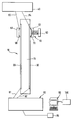
Die einzige Figur der Zeichnung zeigt eine schematische Darstellung einer erfindungsgemäßen Trägervorrichtung 10. Die Trägervorrichtung 10 weist einen langgestreckten (vorzugsweise säulenartigen) Träger 15 und zumindestens zwei Leiter- bzw. Stromschienen 20 und 30 auf. Vorteilhafterweise sind die Leiterschienen 20, 30 glatt und leicht reinigbar ausgebildet. Die Leiterschienen, über die die Strom- und Datenversorgung läuft, sind elektrisch voneinander isoliert angebracht. Die Leiterschienen 20, 30 können über nicht dargestellte Koppelelemente miteinander verbunden werden.The only figure in the drawing shows a schematic representation of a
Ferner ist an der Trägervorrichtung 10 zumindestens ein medizinischer Apparat 40 befestigt. Es können aber serienmäßig mehrere medizinische Apparate an der Trägervorrichtung 10 angeschlossen werden.Furthermore, at least one
Der medizinische Apparat 40 ist beispielsweise mit einer separaten Klemmeinrichtung bzw. Befestigungsklemme oder einem Halter 50 versehen, der über Leitungen 83 und 84 mit dem medizinischen Apparat verbunden ist. Mittels zwei einander gegenüber angeordneter Klemmbacken 61 und 62 ist die Klemmeinrichtung stufenlos an der Trägervorrichtung 10 befestigbar. Der medizinische Apparat 40 ist dadurch leicht entlang der Leiterschienen 20, 30 der Trägervorrichtung 10 zu verschieben.The
Zur Herstellung der mechanischen und elektrischen Verbindung an den Leiterschienen 20, 30 verfügt die Klemmeinrichtung über elektrische Kontakte 60 und 70. Mittels einer Klemmschraube 63 werden die Klemmbacken und die entsprechenden Kontakte an die Leiterschienen 20, 30 der Trägervorrichtung 10 geklemmt. Ebenfalls kann die Befestigungsklemme einen nicht dargestellten Umsetzer des Typs RS-232-CAMUS auf das "Busprotokoll" aufweisen, damit der serienmäßige Anschluß das voneinander unabhängige Funktionieren der einzelnen angeschlossenen medizinischen Apparate ermöglicht.To produce the mechanical and electrical connection on the
Kurze nicht dargestellte Verbindungskabel stellen die elektrische Verbindung zwischen dem medizinischen Apparat 40 und dem Umsetzer her. Die Stromversorgung und die Elektronik für die Datenaufbereitung (spezieller IDK) befindet sich in einer Spannungs- und Datenaustauscheinrichtung 80, z.B. im unteren Bereich des Trägers 15. Von dort aus sind Verbindungen 81 und 82 zum Computer 90 und für die Netzversorgung 85 hergestellt. Damit der Funktionsverlauf des medizinischen Apparates 40 beobachtet werden kann, ist ein Bedienungsmodul 100 mit dem Computer 90 verbunden.Short connecting cables, not shown, establish the electrical connection between the
Claims (14)
Applications Claiming Priority (2)
| Application Number | Priority Date | Filing Date | Title |
|---|---|---|---|
| DE4239625 | 1992-11-26 | ||
| DE4239625A DE4239625C1 (en) | 1992-11-26 | 1992-11-26 | Medical transfusion equipment connecting column - forms connection with data exchange equipment and has two conductors secured by clamp with jaws and electrical contacts |
Publications (2)
| Publication Number | Publication Date |
|---|---|
| EP0602401A1 true EP0602401A1 (en) | 1994-06-22 |
| EP0602401B1 EP0602401B1 (en) | 1997-09-03 |
Family
ID=6473614
Family Applications (1)
| Application Number | Title | Priority Date | Filing Date |
|---|---|---|---|
| EP93118525A Expired - Lifetime EP0602401B1 (en) | 1992-11-26 | 1993-11-17 | Support device for medical apparatus |
Country Status (5)
| Country | Link |
|---|---|
| US (1) | US5625537A (en) |
| EP (1) | EP0602401B1 (en) |
| JP (1) | JPH06205830A (en) |
| DE (2) | DE4239625C1 (en) |
| ES (1) | ES2109413T3 (en) |
Families Citing this family (10)
| Publication number | Priority date | Publication date | Assignee | Title |
|---|---|---|---|---|
| US5984921A (en) * | 1997-05-14 | 1999-11-16 | Ethicon-Endo-Surgery, Inc. | Method and apparatus for applying electrical energy to medical instruments |
| US6250482B1 (en) | 1998-12-15 | 2001-06-26 | Atrium Medical Corporation | Holder for a fluid recovery system |
| DE19940526C1 (en) * | 1999-08-26 | 2001-07-26 | Braun Melsungen Ag | Device for supplying infusion solutions or drugs to patient comprises series of modules, each of which contains infusion device or injection pump, connected to unit providing power in such a way that only one is connected directly to it |
| DE102007053327A1 (en) | 2007-11-08 | 2009-05-14 | Trumpf Medizin Systeme Gmbh + Co.Kg | Medical supply unit for power supply and data transmission in medical apparatus |
| PL2248503T3 (en) | 2009-05-07 | 2013-05-31 | Trumpf Medizin Systeme Gmbh & Co Kg | Medical supply unit with lockable adapters |
| EP2248504B1 (en) | 2009-05-07 | 2013-11-06 | TRUMPF Medizin Systeme GmbH + Co. KG | Medical supply unit with built-in modules |
| ES2551396T3 (en) * | 2012-01-04 | 2015-11-18 | Fresenius Vial Sas | Provision of a support and a medical device |
| NL1039493C2 (en) * | 2012-03-26 | 2013-09-30 | Medicarts Group B V | A SUPPORT SYSTEM FOR SUPPORTING EQUIPMENT, AND EQUIPMENT AND APPARATUS THEREFOR. |
| JP5934447B2 (en) * | 2012-11-09 | 2016-06-15 | フレゼニウス ヴィアル エスアーエスFresenius Vial SAS | Lock system for locking medical devices |
| CN104055576B (en) * | 2013-06-19 | 2016-06-22 | 迈柯唯医疗设备(苏州)有限公司 | Medical hoist tower system |
Citations (3)
| Publication number | Priority date | Publication date | Assignee | Title |
|---|---|---|---|---|
| US3781567A (en) * | 1973-01-17 | 1973-12-25 | W Papsco | Low voltage power distribution system |
| EP0453725A2 (en) * | 1990-04-27 | 1991-10-30 | STAFF GmbH & CO. KG | Transparent contact rail |
| EP0499660A1 (en) * | 1991-02-18 | 1992-08-26 | Siemens Aktiengesellschaft | Device for coupling electrical terminals |
Family Cites Families (3)
| Publication number | Priority date | Publication date | Assignee | Title |
|---|---|---|---|---|
| JPS5384171A (en) * | 1976-12-29 | 1978-07-25 | Fujitsu Ltd | Structure for mounting printed board |
| US4523683A (en) * | 1983-01-31 | 1985-06-18 | Hill-Rom Company, Inc. | Medical service column and mounting bracket |
| DE4030368C1 (en) * | 1990-09-26 | 1991-11-14 | B. Braun Melsungen Ag, 3508 Melsungen, De |
-
1992
- 1992-11-26 DE DE4239625A patent/DE4239625C1/en not_active Expired - Fee Related
-
1993
- 1993-10-27 JP JP5291412A patent/JPH06205830A/en active Pending
- 1993-11-17 EP EP93118525A patent/EP0602401B1/en not_active Expired - Lifetime
- 1993-11-17 ES ES93118525T patent/ES2109413T3/en not_active Expired - Lifetime
- 1993-11-17 DE DE59307264T patent/DE59307264D1/en not_active Expired - Fee Related
-
1996
- 1996-02-09 US US08/599,113 patent/US5625537A/en not_active Expired - Fee Related
Patent Citations (3)
| Publication number | Priority date | Publication date | Assignee | Title |
|---|---|---|---|---|
| US3781567A (en) * | 1973-01-17 | 1973-12-25 | W Papsco | Low voltage power distribution system |
| EP0453725A2 (en) * | 1990-04-27 | 1991-10-30 | STAFF GmbH & CO. KG | Transparent contact rail |
| EP0499660A1 (en) * | 1991-02-18 | 1992-08-26 | Siemens Aktiengesellschaft | Device for coupling electrical terminals |
Also Published As
| Publication number | Publication date |
|---|---|
| ES2109413T3 (en) | 1998-01-16 |
| DE4239625C1 (en) | 1993-08-05 |
| EP0602401B1 (en) | 1997-09-03 |
| US5625537A (en) | 1997-04-29 |
| DE59307264D1 (en) | 1997-10-09 |
| JPH06205830A (en) | 1994-07-26 |
Similar Documents
| Publication | Publication Date | Title |
|---|---|---|
| EP0602401B1 (en) | Support device for medical apparatus | |
| DE3642517C1 (en) | Device adapter | |
| EP0297667B1 (en) | Mobile radio equipment | |
| EP0221278A1 (en) | Support for printed circuits arranged in a rack | |
| EP1892804B1 (en) | Distributor for connecting actuators and/or sensors | |
| DE4124487A1 (en) | Adaptor plate for bus=bar - holds several flush-mounted electrical units in clips which are adjustable to suit width of unit | |
| EP0189522B1 (en) | Terminal board for connection of electrical apparatus | |
| EP0596344B1 (en) | Connector device for ECG electrodes | |
| EP0821841B1 (en) | Arrangement for connecting power supply lines to an electronic device and cubicle with such an arrangement | |
| DE102005022343A1 (en) | Safe mounting and supply of electrical power to a roof mounted X ray unit using a surface conductor strip | |
| DE10148470A1 (en) | Modular equipment connecting automation system components mechanically and electrically, includes bus segments with star-shaped coupling | |
| EP1403969B1 (en) | Device for apparatus power supply | |
| EP0461454A2 (en) | Distribution device | |
| DE3527914C2 (en) | ||
| DE2833022A1 (en) | CIRCUIT ARRANGEMENT FOR REMOTE POWERING FROM INTERFACES OF A DEVICE FOR MESSAGE TRANSMISSION TECHNOLOGY | |
| EP1566864B1 (en) | Socketmodule for a head of a medical ceiling mount | |
| EP0180856A2 (en) | Electrical apparatus | |
| EP0897187A2 (en) | Switch assembly with modular powerbus | |
| DE102019121914B3 (en) | Device for coupling at least two electronic devices and a system with at least two such devices | |
| EP0191943B1 (en) | Rail-mounted terminal assembly | |
| DE2342988A1 (en) | Series clamp for bus-bar with separating facility - uses S-shaped connection strap between wire terminal and busbar | |
| CH624512A5 (en) | Controller for a thyristor-supplied DC control drive | |
| DE19650988A1 (en) | Terminal block with built-in or pluggable electronics e.g. for computer | |
| EP0349782A1 (en) | Adapter for a bus bar system bus bar | |
| DE19940526C1 (en) | Device for supplying infusion solutions or drugs to patient comprises series of modules, each of which contains infusion device or injection pump, connected to unit providing power in such a way that only one is connected directly to it |
Legal Events
| Date | Code | Title | Description |
|---|---|---|---|
| PUAI | Public reference made under article 153(3) epc to a published international application that has entered the european phase |
Free format text: ORIGINAL CODE: 0009012 |
|
| AK | Designated contracting states |
Kind code of ref document: A1 Designated state(s): DE ES FR GB IT |
|
| 17P | Request for examination filed |
Effective date: 19940707 |
|
| 17Q | First examination report despatched |
Effective date: 19960226 |
|
| GRAG | Despatch of communication of intention to grant |
Free format text: ORIGINAL CODE: EPIDOS AGRA |
|
| GRAH | Despatch of communication of intention to grant a patent |
Free format text: ORIGINAL CODE: EPIDOS IGRA |
|
| GRAH | Despatch of communication of intention to grant a patent |
Free format text: ORIGINAL CODE: EPIDOS IGRA |
|
| GRAA | (expected) grant |
Free format text: ORIGINAL CODE: 0009210 |
|
| AK | Designated contracting states |
Kind code of ref document: B1 Designated state(s): DE ES FR GB IT |
|
| GBT | Gb: translation of ep patent filed (gb section 77(6)(a)/1977) |
Effective date: 19970905 |
|
| REF | Corresponds to: |
Ref document number: 59307264 Country of ref document: DE Date of ref document: 19971009 |
|
| ITF | It: translation for a ep patent filed |
Owner name: STUDIO TORTA S.R.L. |
|
| ET | Fr: translation filed | ||
| REG | Reference to a national code |
Ref country code: ES Ref legal event code: FG2A Ref document number: 2109413 Country of ref document: ES Kind code of ref document: T3 |
|
| PLBE | No opposition filed within time limit |
Free format text: ORIGINAL CODE: 0009261 |
|
| STAA | Information on the status of an ep patent application or granted ep patent |
Free format text: STATUS: NO OPPOSITION FILED WITHIN TIME LIMIT |
|
| 26N | No opposition filed | ||
| REG | Reference to a national code |
Ref country code: GB Ref legal event code: IF02 |
|
| PGFP | Annual fee paid to national office [announced via postgrant information from national office to epo] |
Ref country code: GB Payment date: 20031028 Year of fee payment: 11 |
|
| PGFP | Annual fee paid to national office [announced via postgrant information from national office to epo] |
Ref country code: FR Payment date: 20031118 Year of fee payment: 11 |
|
| PGFP | Annual fee paid to national office [announced via postgrant information from national office to epo] |
Ref country code: ES Payment date: 20031121 Year of fee payment: 11 |
|
| PG25 | Lapsed in a contracting state [announced via postgrant information from national office to epo] |
Ref country code: GB Free format text: LAPSE BECAUSE OF NON-PAYMENT OF DUE FEES Effective date: 20041117 |
|
| PG25 | Lapsed in a contracting state [announced via postgrant information from national office to epo] |
Ref country code: ES Free format text: LAPSE BECAUSE OF NON-PAYMENT OF DUE FEES Effective date: 20041118 |
|
| GBPC | Gb: european patent ceased through non-payment of renewal fee |
Effective date: 20041117 |
|
| PG25 | Lapsed in a contracting state [announced via postgrant information from national office to epo] |
Ref country code: FR Free format text: LAPSE BECAUSE OF NON-PAYMENT OF DUE FEES Effective date: 20050729 |
|
| REG | Reference to a national code |
Ref country code: FR Ref legal event code: ST |
|
| PG25 | Lapsed in a contracting state [announced via postgrant information from national office to epo] |
Ref country code: IT Free format text: LAPSE BECAUSE OF NON-PAYMENT OF DUE FEES;WARNING: LAPSES OF ITALIAN PATENTS WITH EFFECTIVE DATE BEFORE 2007 MAY HAVE OCCURRED AT ANY TIME BEFORE 2007. THE CORRECT EFFECTIVE DATE MAY BE DIFFERENT FROM THE ONE RECORDED. Effective date: 20051117 |
|
| PGFP | Annual fee paid to national office [announced via postgrant information from national office to epo] |
Ref country code: DE Payment date: 20060127 Year of fee payment: 13 |
|
| REG | Reference to a national code |
Ref country code: ES Ref legal event code: FD2A Effective date: 20041118 |
|
| PG25 | Lapsed in a contracting state [announced via postgrant information from national office to epo] |
Ref country code: DE Free format text: LAPSE BECAUSE OF NON-PAYMENT OF DUE FEES Effective date: 20070601 |