EP0602401A1 - Dispositif de support pour appareils médicaux - Google Patents
Dispositif de support pour appareils médicaux Download PDFInfo
- Publication number
- EP0602401A1 EP0602401A1 EP93118525A EP93118525A EP0602401A1 EP 0602401 A1 EP0602401 A1 EP 0602401A1 EP 93118525 A EP93118525 A EP 93118525A EP 93118525 A EP93118525 A EP 93118525A EP 0602401 A1 EP0602401 A1 EP 0602401A1
- Authority
- EP
- European Patent Office
- Prior art keywords
- medical apparatus
- carrier
- clamping
- conductor rails
- clamping device
- Prior art date
- Legal status (The legal status is an assumption and is not a legal conclusion. Google has not performed a legal analysis and makes no representation as to the accuracy of the status listed.)
- Granted
Links
Images
Classifications
-
- A—HUMAN NECESSITIES
- A61—MEDICAL OR VETERINARY SCIENCE; HYGIENE
- A61G—TRANSPORT, PERSONAL CONVEYANCES, OR ACCOMMODATION SPECIALLY ADAPTED FOR PATIENTS OR DISABLED PERSONS; OPERATING TABLES OR CHAIRS; CHAIRS FOR DENTISTRY; FUNERAL DEVICES
- A61G13/00—Operating tables; Auxiliary appliances therefor
- A61G13/10—Parts, details or accessories
- A61G13/107—Supply appliances
-
- A—HUMAN NECESSITIES
- A61—MEDICAL OR VETERINARY SCIENCE; HYGIENE
- A61G—TRANSPORT, PERSONAL CONVEYANCES, OR ACCOMMODATION SPECIALLY ADAPTED FOR PATIENTS OR DISABLED PERSONS; OPERATING TABLES OR CHAIRS; CHAIRS FOR DENTISTRY; FUNERAL DEVICES
- A61G12/00—Accommodation for nursing, e.g. in hospitals, not covered by groups A61G1/00 - A61G11/00, e.g. trolleys for transport of medicaments or food; Prescription lists
- A61G12/002—Supply appliances, e.g. columns for gas, fluid, electricity supply
-
- A—HUMAN NECESSITIES
- A61—MEDICAL OR VETERINARY SCIENCE; HYGIENE
- A61M—DEVICES FOR INTRODUCING MEDIA INTO, OR ONTO, THE BODY; DEVICES FOR TRANSDUCING BODY MEDIA OR FOR TAKING MEDIA FROM THE BODY; DEVICES FOR PRODUCING OR ENDING SLEEP OR STUPOR
- A61M5/00—Devices for bringing media into the body in a subcutaneous, intra-vascular or intramuscular way; Accessories therefor, e.g. filling or cleaning devices, arm-rests
- A61M5/14—Infusion devices, e.g. infusing by gravity; Blood infusion; Accessories therefor
- A61M5/1414—Hanging-up devices
- A61M5/1415—Stands, brackets or the like for supporting infusion accessories
-
- H—ELECTRICITY
- H01—ELECTRIC ELEMENTS
- H01R—ELECTRICALLY-CONDUCTIVE CONNECTIONS; STRUCTURAL ASSOCIATIONS OF A PLURALITY OF MUTUALLY-INSULATED ELECTRICAL CONNECTING ELEMENTS; COUPLING DEVICES; CURRENT COLLECTORS
- H01R25/00—Coupling parts adapted for simultaneous co-operation with two or more identical counterparts, e.g. for distributing energy to two or more circuits
- H01R25/14—Rails or bus-bars constructed so that the counterparts can be connected thereto at any point along their length
- H01R25/142—Their counterparts
-
- H—ELECTRICITY
- H01—ELECTRIC ELEMENTS
- H01R—ELECTRICALLY-CONDUCTIVE CONNECTIONS; STRUCTURAL ASSOCIATIONS OF A PLURALITY OF MUTUALLY-INSULATED ELECTRICAL CONNECTING ELEMENTS; COUPLING DEVICES; CURRENT COLLECTORS
- H01R41/00—Non-rotary current collectors for maintaining contact between moving and stationary parts of an electric circuit
-
- H—ELECTRICITY
- H01—ELECTRIC ELEMENTS
- H01R—ELECTRICALLY-CONDUCTIVE CONNECTIONS; STRUCTURAL ASSOCIATIONS OF A PLURALITY OF MUTUALLY-INSULATED ELECTRICAL CONNECTING ELEMENTS; COUPLING DEVICES; CURRENT COLLECTORS
- H01R2201/00—Connectors or connections adapted for particular applications
- H01R2201/04—Connectors or connections adapted for particular applications for network, e.g. LAN connectors
-
- H—ELECTRICITY
- H01—ELECTRIC ELEMENTS
- H01R—ELECTRICALLY-CONDUCTIVE CONNECTIONS; STRUCTURAL ASSOCIATIONS OF A PLURALITY OF MUTUALLY-INSULATED ELECTRICAL CONNECTING ELEMENTS; COUPLING DEVICES; CURRENT COLLECTORS
- H01R2201/00—Connectors or connections adapted for particular applications
- H01R2201/06—Connectors or connections adapted for particular applications for computer periphery
-
- H—ELECTRICITY
- H01—ELECTRIC ELEMENTS
- H01R—ELECTRICALLY-CONDUCTIVE CONNECTIONS; STRUCTURAL ASSOCIATIONS OF A PLURALITY OF MUTUALLY-INSULATED ELECTRICAL CONNECTING ELEMENTS; COUPLING DEVICES; CURRENT COLLECTORS
- H01R2201/00—Connectors or connections adapted for particular applications
- H01R2201/12—Connectors or connections adapted for particular applications for medicine and surgery
-
- H—ELECTRICITY
- H01—ELECTRIC ELEMENTS
- H01R—ELECTRICALLY-CONDUCTIVE CONNECTIONS; STRUCTURAL ASSOCIATIONS OF A PLURALITY OF MUTUALLY-INSULATED ELECTRICAL CONNECTING ELEMENTS; COUPLING DEVICES; CURRENT COLLECTORS
- H01R4/00—Electrically-conductive connections between two or more conductive members in direct contact, i.e. touching one another; Means for effecting or maintaining such contact; Electrically-conductive connections having two or more spaced connecting locations for conductors and using contact members penetrating insulation
- H01R4/28—Clamped connections, spring connections
- H01R4/38—Clamped connections, spring connections utilising a clamping member acted on by screw or nut
Definitions
- the invention relates to a carrier device for medical apparatus according to the preamble of claim 1.
- Such a carrier device is known from DE-C-40 30 368.
- medical devices for. B. wirelessly set up in the form of infusion equipment.
- the largest area of application is currently in patient monitoring and infusion therapy.
- the carrier device is provided with a coupling device and the medical apparatus is equipped with a clamping device.
- This known carrier device has a column for holding a plurality of infusion devices, onto which the infusion devices, which are U-shaped, are pushed. Strip-shaped support and coupling elements are attached to the column.
- the slide-on infusion devices have groove-like guide and plug elements.
- the mechanical connection of the column and infusion devices is established via the strip-shaped support elements and corresponding groove-like guide elements in the infusion devices.
- the electrical connection is made via the coupling and corresponding connector elements.
- the electrical power supply of the infusion devices comes from the inside of the device carrier.
- the infusion devices can, if not slipped on the equipment rack, provided with a rechargeable battery. If necessary, this accumulator is pushed onto the infusion device.
- Another carrier device is known from DE-34 02 885 and has a free-standing supply column which is designed as a device carrier.
- This column has vertical, in pairs running on the front and back of the column rails, in which brackets, holders and accessories can be moved and locked with slide locks. These coupling elements are used to mechanically connect the column and medical devices.
- the column contains fluid lines and electrical lines, so that here too the power supply of the medical apparatus takes place from the inside of the device after the electrical line of the medical apparatus has been connected to the corresponding supply outlet of the column.
- the coupling device of the carrier device according to the invention has two conductor rails which are electrically insulated from one another and run continuously along the longitudinal extent of the carrier. These conductor rails provide the power supply or data transmission and the mechanical attachment of at least one medical device. This means that, with regard to the electrical part, the power supply, data supply and personnel calls are carried out entirely via the conductor rails. This has the advantage that it is largely possible to dispense with multiple and separate cable services, as a result of which the preparation effort required for the use of the medical apparatus is largely reduced.
- the conductor rails extending continuously along the longitudinal direction allow a continuous attachment and displacement of several medical devices. Another advantage is that the medical devices can be attached and moved anywhere on the rails without having to remove the apparatus from the conductor rails.
- the conductor rails of the carrier device are designed as smooth metal rails. This has the advantage that the conductor rails are easier to clean and the carrier device meets the hygienic requirements.
- the conductor rails of the carrier device are connected to one another via coupling elements, so that a further connection of conductor rails to one another is made possible.
- the carrier device has a voltage and data exchange device which is arranged at the base of the carrier. This has the advantage that central control and monitoring of several medical devices connected to the carrier device is possible.
- the voltage and data exchange device is designed as a power supply and bus interface. This device allows simultaneous power supply and data transfer between the connected medical devices and a computer.
- the voltage and data exchange device can be connected to a computer or PC.
- the voltage data exchange device can also be connected to a power source or a power supply network, so that the power supply is ensured.
- the invention further relates to a carrier according to claim 8, which is an independently tradable object.
- the invention relates to a medical apparatus according to one of claims 9 to 15, which preferably has a clamping device with two electrical contacts which can be contacted with the conductor rails, so that the electrical connection takes place without additional cable connection.
- the clamping device advantageously has two clamping jaws arranged opposite one another, which can be actuated by means of a clamping screw or another suitable clamping device. This results in the further advantage that the electrical contact occurs simultaneously with the mechanical locking, that is to say a mechanical and electrical connection is established in a simple operation. Such a clamping device also enables the medical apparatus to be easily moved along the conductor rails without the electrical connection being interrupted.
- the medical apparatus has an integrated rechargeable accumulator, which has the advantage that the medical apparatus always has an individually charged power source. In the event of a power failure bridging or a mobile use of the medical apparatus during patient transportation, the power supply is thus guaranteed.
- primary cells for supplying power to the infusion apparatus can advantageously be dispensed with.
- the medical apparatus is equipped with a converter integrated in the clamping device, which gives the advantage that different data transmission techniques can be used, for example in the case of an emergency operation.
- the clamping device is a separate component that can be connected to the medical apparatus via a cable connection in order to easily replace the clamping device, e.g. after a malfunction.
- the clamping device could also be designed as an integral component of the medical apparatus.
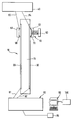
- the only figure in the drawing shows a schematic representation of a carrier device 10 according to the invention.
- the carrier device 10 has an elongated (preferably columnar) carrier 15 and at least two conductor or busbars 20 and 30.
- the conductor rails 20, 30 are smooth and easy to clean.
- the conductor rails, through which the power and data supply runs, are electrically insulated from each other.
- the conductor rails 20, 30 can be connected to one another via coupling elements, not shown.
- At least one medical apparatus 40 is attached to the carrier device 10.
- several medical devices can be connected to the carrier device 10 as standard.
- the medical apparatus 40 is provided, for example, with a separate clamping device or fastening clamp or a holder 50 which is connected to the medical apparatus via lines 83 and 84.
- the clamping device can be attached to the carrier device 10 in a stepless manner by means of two clamping jaws 61 and 62 arranged opposite one another. The medical apparatus 40 can thereby be easily moved along the conductor rails 20, 30 of the carrier device 10.
- the clamping device has electrical contacts 60 and 70.
- the clamping jaws and the corresponding contacts are clamped to the conductor rails 20, 30 of the carrier device 10 by means of a clamping screw 63.
- the fastening clamp can also have a converter (not shown) of the type RS-232-CAMUS to the "bus protocol" so that the standard connection enables the independent connection of the individual connected medical devices.
- Short connecting cables establish the electrical connection between the medical apparatus 40 and the converter.
- the power supply and the electronics for data processing are located in a voltage and data exchange device 80, e.g. in the lower area of the carrier 15. From there, connections 81 and 82 to the computer 90 and for the power supply 85 are established.
- An operating module 100 is connected to the computer 90 so that the functional course of the medical apparatus 40 can be observed.
Applications Claiming Priority (2)
| Application Number | Priority Date | Filing Date | Title |
|---|---|---|---|
| DE4239625 | 1992-11-26 | ||
| DE4239625A DE4239625C1 (en) | 1992-11-26 | 1992-11-26 | Medical transfusion equipment connecting column - forms connection with data exchange equipment and has two conductors secured by clamp with jaws and electrical contacts |
Publications (2)
| Publication Number | Publication Date |
|---|---|
| EP0602401A1 true EP0602401A1 (fr) | 1994-06-22 |
| EP0602401B1 EP0602401B1 (fr) | 1997-09-03 |
Family
ID=6473614
Family Applications (1)
| Application Number | Title | Priority Date | Filing Date |
|---|---|---|---|
| EP93118525A Expired - Lifetime EP0602401B1 (fr) | 1992-11-26 | 1993-11-17 | Dispositif de support pour appareils médicaux |
Country Status (5)
| Country | Link |
|---|---|
| US (1) | US5625537A (fr) |
| EP (1) | EP0602401B1 (fr) |
| JP (1) | JPH06205830A (fr) |
| DE (2) | DE4239625C1 (fr) |
| ES (1) | ES2109413T3 (fr) |
Families Citing this family (10)
| Publication number | Priority date | Publication date | Assignee | Title |
|---|---|---|---|---|
| US5984921A (en) * | 1997-05-14 | 1999-11-16 | Ethicon-Endo-Surgery, Inc. | Method and apparatus for applying electrical energy to medical instruments |
| US6250482B1 (en) | 1998-12-15 | 2001-06-26 | Atrium Medical Corporation | Holder for a fluid recovery system |
| DE19940526C1 (de) * | 1999-08-26 | 2001-07-26 | Braun Melsungen Ag | Medizinische Dosierversorgungsvorrichtung |
| DE102007053327A1 (de) | 2007-11-08 | 2009-05-14 | Trumpf Medizin Systeme Gmbh + Co.Kg | Medizinische Versorgungseinheit zur Stromversorgung und Datenübertragung bei medizinischen Apparaten |
| PL2248503T3 (pl) | 2009-05-07 | 2013-05-31 | Trumpf Medizin Systeme Gmbh & Co Kg | Medyczna jednostka zasilająca z blokowanymi adapterami |
| EP2248504B1 (fr) | 2009-05-07 | 2013-11-06 | TRUMPF Medizin Systeme GmbH + Co. KG | Unité d'alimentation médicale dotée de modules encastrables |
| JP2015503968A (ja) | 2012-01-04 | 2015-02-05 | フレゼニウス ヴィアル エスアーエスFresenius Vial SAS | ラック及び医療機器の配置構造 |
| NL1039493C2 (nl) * | 2012-03-26 | 2013-09-30 | Medicarts Group B V | Draagsysteem voor het dragen van apparatuur, alsmede apparatuur en inrichtingen daarvoor. |
| JP5934447B2 (ja) * | 2012-11-09 | 2016-06-15 | フレゼニウス ヴィアル エスアーエスFresenius Vial SAS | 医療装置をロックするロックシステム |
| CN104055576B (zh) * | 2013-06-19 | 2016-06-22 | 迈柯唯医疗设备(苏州)有限公司 | 医用吊塔系统 |
Citations (3)
| Publication number | Priority date | Publication date | Assignee | Title |
|---|---|---|---|---|
| US3781567A (en) * | 1973-01-17 | 1973-12-25 | W Papsco | Low voltage power distribution system |
| EP0453725A2 (fr) * | 1990-04-27 | 1991-10-30 | STAFF GmbH & CO. KG | Barre conductrice transparente |
| EP0499660A1 (fr) * | 1991-02-18 | 1992-08-26 | Siemens Aktiengesellschaft | Dispositif de connexion pour des terminaux électriques |
Family Cites Families (3)
| Publication number | Priority date | Publication date | Assignee | Title |
|---|---|---|---|---|
| JPS5384171A (en) * | 1976-12-29 | 1978-07-25 | Fujitsu Ltd | Structure for mounting printed board |
| US4523683A (en) * | 1983-01-31 | 1985-06-18 | Hill-Rom Company, Inc. | Medical service column and mounting bracket |
| DE4030368C1 (fr) * | 1990-09-26 | 1991-11-14 | B. Braun Melsungen Ag, 3508 Melsungen, De |
-
1992
- 1992-11-26 DE DE4239625A patent/DE4239625C1/de not_active Expired - Fee Related
-
1993
- 1993-10-27 JP JP5291412A patent/JPH06205830A/ja active Pending
- 1993-11-17 ES ES93118525T patent/ES2109413T3/es not_active Expired - Lifetime
- 1993-11-17 EP EP93118525A patent/EP0602401B1/fr not_active Expired - Lifetime
- 1993-11-17 DE DE59307264T patent/DE59307264D1/de not_active Expired - Fee Related
-
1996
- 1996-02-09 US US08/599,113 patent/US5625537A/en not_active Expired - Fee Related
Patent Citations (3)
| Publication number | Priority date | Publication date | Assignee | Title |
|---|---|---|---|---|
| US3781567A (en) * | 1973-01-17 | 1973-12-25 | W Papsco | Low voltage power distribution system |
| EP0453725A2 (fr) * | 1990-04-27 | 1991-10-30 | STAFF GmbH & CO. KG | Barre conductrice transparente |
| EP0499660A1 (fr) * | 1991-02-18 | 1992-08-26 | Siemens Aktiengesellschaft | Dispositif de connexion pour des terminaux électriques |
Also Published As
| Publication number | Publication date |
|---|---|
| JPH06205830A (ja) | 1994-07-26 |
| DE59307264D1 (de) | 1997-10-09 |
| DE4239625C1 (en) | 1993-08-05 |
| ES2109413T3 (es) | 1998-01-16 |
| US5625537A (en) | 1997-04-29 |
| EP0602401B1 (fr) | 1997-09-03 |
Similar Documents
| Publication | Publication Date | Title |
|---|---|---|
| EP0602401B1 (fr) | Dispositif de support pour appareils médicaux | |
| DE3642517C1 (de) | Geraeteadapter | |
| EP1892804B1 (fr) | Répartiteur destiné à relier des actionneurs et/ou des capteurs | |
| DE4124487A1 (de) | Adapter | |
| EP0189522B1 (fr) | Plaque à bornes pour la connexion d'appareils électriques | |
| DE3721806A1 (de) | Mobilfunkanlage | |
| EP0821841B1 (fr) | Systeme de raccordement de lignes d'alimentation a un appareil electronique et armoire equipee d'un tel systeme | |
| DE102005022343A1 (de) | Röntgenvorrichtung mit einer an einem Deckenstativ angebrachten Röntgenquelle | |
| DE10148470A1 (de) | Vorrichtung und Verfahren zum elektrischen und mechanischen Verbinden von Komponenten eines Automatisierungssystems | |
| DE2251020B2 (de) | Anschlussvorrichtung | |
| EP1403969B1 (fr) | Dispoditif d'alimentation de puissance pour un appareil | |
| EP0461454A2 (fr) | Dispositif de distribution | |
| DE3527914C2 (fr) | ||
| DE2833022A1 (de) | Schaltungsanordnung zur fernspeisung von zwischenstellen einer einrichtung der nachrichtenuebertragungstechnik | |
| EP1566864B1 (fr) | Module de prise de courant pour une tête de support de plafond médical | |
| EP0180856A2 (fr) | Appareil électrique | |
| EP0897187A2 (fr) | Ensemble d'interrupteurs avec bus de puissance modulaire | |
| DE102019121914B3 (de) | Vorrichtung zum Koppeln von mindestens zwei elektronischen Geräten sowie System mit mindestens zwei solcher Vorrichtungen | |
| DE2342988A1 (de) | Reihenklemme mit trenneinrichtung fuer eine sammelschiene | |
| EP0432286B1 (fr) | Interrupteur à bouton-poussoir, suspendu et utilisable pour la commande d'appareils de levage et/ou installations de grue | |
| CH624512A5 (en) | Controller for a thyristor-supplied DC control drive | |
| DE19650988A1 (de) | Reihenklemme mit eingebauter oder aufsteckbarer Elektronik | |
| EP0349782A1 (fr) | Adaptateur pour une barre conductrice d'un système de barres omnibus | |
| DE19940526C1 (de) | Medizinische Dosierversorgungsvorrichtung | |
| DE3214484C2 (de) | Vorrichtung zur optischen Anzeige des Betriebszustandes eines wegen einer Isolation oder Kapselung unzulänglichen Leiters eines Energieversorgungsnetzes |
Legal Events
| Date | Code | Title | Description |
|---|---|---|---|
| PUAI | Public reference made under article 153(3) epc to a published international application that has entered the european phase |
Free format text: ORIGINAL CODE: 0009012 |
|
| AK | Designated contracting states |
Kind code of ref document: A1 Designated state(s): DE ES FR GB IT |
|
| 17P | Request for examination filed |
Effective date: 19940707 |
|
| 17Q | First examination report despatched |
Effective date: 19960226 |
|
| GRAG | Despatch of communication of intention to grant |
Free format text: ORIGINAL CODE: EPIDOS AGRA |
|
| GRAH | Despatch of communication of intention to grant a patent |
Free format text: ORIGINAL CODE: EPIDOS IGRA |
|
| GRAH | Despatch of communication of intention to grant a patent |
Free format text: ORIGINAL CODE: EPIDOS IGRA |
|
| GRAA | (expected) grant |
Free format text: ORIGINAL CODE: 0009210 |
|
| AK | Designated contracting states |
Kind code of ref document: B1 Designated state(s): DE ES FR GB IT |
|
| GBT | Gb: translation of ep patent filed (gb section 77(6)(a)/1977) |
Effective date: 19970905 |
|
| REF | Corresponds to: |
Ref document number: 59307264 Country of ref document: DE Date of ref document: 19971009 |
|
| ITF | It: translation for a ep patent filed |
Owner name: STUDIO TORTA S.R.L. |
|
| ET | Fr: translation filed | ||
| REG | Reference to a national code |
Ref country code: ES Ref legal event code: FG2A Ref document number: 2109413 Country of ref document: ES Kind code of ref document: T3 |
|
| PLBE | No opposition filed within time limit |
Free format text: ORIGINAL CODE: 0009261 |
|
| STAA | Information on the status of an ep patent application or granted ep patent |
Free format text: STATUS: NO OPPOSITION FILED WITHIN TIME LIMIT |
|
| 26N | No opposition filed | ||
| REG | Reference to a national code |
Ref country code: GB Ref legal event code: IF02 |
|
| PGFP | Annual fee paid to national office [announced via postgrant information from national office to epo] |
Ref country code: GB Payment date: 20031028 Year of fee payment: 11 |
|
| PGFP | Annual fee paid to national office [announced via postgrant information from national office to epo] |
Ref country code: FR Payment date: 20031118 Year of fee payment: 11 |
|
| PGFP | Annual fee paid to national office [announced via postgrant information from national office to epo] |
Ref country code: ES Payment date: 20031121 Year of fee payment: 11 |
|
| PG25 | Lapsed in a contracting state [announced via postgrant information from national office to epo] |
Ref country code: GB Free format text: LAPSE BECAUSE OF NON-PAYMENT OF DUE FEES Effective date: 20041117 |
|
| PG25 | Lapsed in a contracting state [announced via postgrant information from national office to epo] |
Ref country code: ES Free format text: LAPSE BECAUSE OF NON-PAYMENT OF DUE FEES Effective date: 20041118 |
|
| GBPC | Gb: european patent ceased through non-payment of renewal fee |
Effective date: 20041117 |
|
| PG25 | Lapsed in a contracting state [announced via postgrant information from national office to epo] |
Ref country code: FR Free format text: LAPSE BECAUSE OF NON-PAYMENT OF DUE FEES Effective date: 20050729 |
|
| REG | Reference to a national code |
Ref country code: FR Ref legal event code: ST |
|
| PG25 | Lapsed in a contracting state [announced via postgrant information from national office to epo] |
Ref country code: IT Free format text: LAPSE BECAUSE OF NON-PAYMENT OF DUE FEES;WARNING: LAPSES OF ITALIAN PATENTS WITH EFFECTIVE DATE BEFORE 2007 MAY HAVE OCCURRED AT ANY TIME BEFORE 2007. THE CORRECT EFFECTIVE DATE MAY BE DIFFERENT FROM THE ONE RECORDED. Effective date: 20051117 |
|
| PGFP | Annual fee paid to national office [announced via postgrant information from national office to epo] |
Ref country code: DE Payment date: 20060127 Year of fee payment: 13 |
|
| REG | Reference to a national code |
Ref country code: ES Ref legal event code: FD2A Effective date: 20041118 |
|
| PG25 | Lapsed in a contracting state [announced via postgrant information from national office to epo] |
Ref country code: DE Free format text: LAPSE BECAUSE OF NON-PAYMENT OF DUE FEES Effective date: 20070601 |