EP0602399A1 - Dispositif de rayonnages pour l'entreposage d'éléments moulés en béton pendant leur durcissement - Google Patents
Dispositif de rayonnages pour l'entreposage d'éléments moulés en béton pendant leur durcissement Download PDFInfo
- Publication number
- EP0602399A1 EP0602399A1 EP93118432A EP93118432A EP0602399A1 EP 0602399 A1 EP0602399 A1 EP 0602399A1 EP 93118432 A EP93118432 A EP 93118432A EP 93118432 A EP93118432 A EP 93118432A EP 0602399 A1 EP0602399 A1 EP 0602399A1
- Authority
- EP
- European Patent Office
- Prior art keywords
- supports
- boards
- underlay
- shelf
- storage
- Prior art date
- Legal status (The legal status is an assumption and is not a legal conclusion. Google has not performed a legal analysis and makes no representation as to the accuracy of the status listed.)
- Granted
Links
Images

Classifications
-
- B—PERFORMING OPERATIONS; TRANSPORTING
- B65—CONVEYING; PACKING; STORING; HANDLING THIN OR FILAMENTARY MATERIAL
- B65G—TRANSPORT OR STORAGE DEVICES, e.g. CONVEYORS FOR LOADING OR TIPPING, SHOP CONVEYOR SYSTEMS OR PNEUMATIC TUBE CONVEYORS
- B65G1/00—Storing articles, individually or in orderly arrangement, in warehouses or magazines
- B65G1/02—Storage devices
- B65G1/04—Storage devices mechanical
- B65G1/0464—Storage devices mechanical with access from above
-
- B—PERFORMING OPERATIONS; TRANSPORTING
- B28—WORKING CEMENT, CLAY, OR STONE
- B28B—SHAPING CLAY OR OTHER CERAMIC COMPOSITIONS; SHAPING SLAG; SHAPING MIXTURES CONTAINING CEMENTITIOUS MATERIAL, e.g. PLASTER
- B28B13/00—Feeding the unshaped material to moulds or apparatus for producing shaped articles; Discharging shaped articles from such moulds or apparatus
- B28B13/04—Discharging the shaped articles
-
- B—PERFORMING OPERATIONS; TRANSPORTING
- B65—CONVEYING; PACKING; STORING; HANDLING THIN OR FILAMENTARY MATERIAL
- B65G—TRANSPORT OR STORAGE DEVICES, e.g. CONVEYORS FOR LOADING OR TIPPING, SHOP CONVEYOR SYSTEMS OR PNEUMATIC TUBE CONVEYORS
- B65G1/00—Storing articles, individually or in orderly arrangement, in warehouses or magazines
- B65G1/02—Storage devices
- B65G1/14—Stack holders or separators
Definitions
- the invention relates to a shelf system for the intermediate storage of underlay boards covered with molded articles made of concrete, consisting of a shelf and a device for storage and retrieval in the vertical direction from above or upwards. Since freshly formed concrete bodies cannot yet be stacked, shelves are required in machine production in order to accommodate the molded bodies produced on a limited base area. Shelves that can be operated from above have the advantage that they do not require any intermediate aisles and therefore make particularly good use of the available floor space.
- the invention has for its object to provide a space-saving shelving system that is simple and yet can be operated fully automatically.
- the supports used here can be fixedly attached to the scaffold, which not only considerably simplifies the manufacture of the shelf, but also eliminates the disturbances associated with the operation of movable supports.
- the outline of the underlay boards is adapted to the support arrangement in such a way that they can be moved past the supports in the vertical direction, only to be moved horizontally at the intended storage location and then to be placed on the supports. Conversely, when moving out after lifting the underlay board, only a small horizontal movement is required to lift the board vertically upwards out of the shaft.
- the aforementioned horizontal movement which is necessary in order to bring the underlay board or projections firmly attached to it with the supports in register or out of register, can be carried out by the gripper without great effort. It can be a longitudinal movement, which may coincide with the gripper running direction.
- a rectangular underlay board can have two edge cutouts on each of the longitudinal or transverse edges, and short cantilever arms can be attached to the rack structure, which protrude into the edge cutouts and are not wider than these.
- the horizontal movement would be a longitudinal movement in the direction of the relevant edges over the width of the cutouts.
- a special shape of the contour of the underlay boards can be dispensed with. It is proposed that conventional rectangular backing boards are used, the corners of which form the projections, and that the horizontal movement is a rotary movement.
- the shelf is a post field of free-standing vertical posts, which are arranged in a surface grid corresponding to the format of the underlay boards and to which supports are attached. Such a system has the impressive advantage that it can be used in existing manufacturing plants for concrete bodies that work with proven smooth-edged underlay boards.
- the construction of the shelf in the form of individually standing posts is extremely simple and inexpensive. The posts only need to be placed exactly at a distance and aligned vertically. It is particularly expedient if the underlay boards are square and the supports of the posts form a circular support surface.
- a liftable and lowerable gripper that can be moved above the post field, which can pick up at least one board in a horizontal position and rotate it by a small angle.
- the arrangement is expediently made such that the underlay boards rest in a bearing position with the corners on the supports in a position substantially parallel to the post grid and come past the supports in a rotated driving position during vertical movement.
- the size of the post field can largely depend on the local conditions.
- Four posts form a storage shaft.
- a storage shaft can be connected to this by means of two additional posts, and so on. It is expedient if the post field forms a longitudinal row of a plurality of storage shafts lying next to one another and the gripper which can be moved in the longitudinal direction is equipped with as many individual rotatable gripping tools lying next to one another as storage shafts lying next to one another are provided.
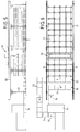
- FIGS. 1 and 2 There are nine posts 1 arranged in a square grid shown, on which annular disk-shaped supports 2 are arranged perpendicular to the post axis. They lie in horizontal layers of certain height distances, which depend on the height of the concrete moldings that are to be placed on the shelf for setting. These concrete bodies, not shown, lie on square base boards 3, which are brought up in a horizontal position by means of a gripper 4.
- FIG. 1 Of the gripper 4, only the part of special interest with the two horizontally displaceable gripping tools 5 is shown in FIG. 1. These are slidably mounted with their upper part in a horizontal guide 6 and are actuated by means of a lifting cylinder 7. Furthermore, the gripping tools 5 have arms hanging down and at the lower end each an inwardly standing strip-shaped flange 8.
- the horizontal guide 6 and the gripping tools 5 can be pivoted by approximately 15 ° with respect to a vertical pivot axis 10 by means of a vertical bearing 9.
- an electric motor 11 serves as the swivel drive.
- the swivel movement can also be carried out by means of a lifting cylinder via a lever linkage.
- the gripper which in this case only grips a support board 3, is moved exactly in the middle over one of the storage shafts and is in the inclined dash-dotted driving position when lowering.
- the gripper swivels to the right with respect to FIG. 2 and brings the underlay board 3 into the grid-parallel storage position shown in full extension. In this angular position, the board is lowered so far that it rests with its four corners on the four adjacent supports 2.
- the order is reversed for outsourcing.
- the underlay board is first raised a little in its storage position and then in the Swiveled driving position and so lifted past the overlying supports 2 upwards.
- the detailed representation of a post according to Figures 3 and 4 shows above all its attachment to the foundation.
- the post body is simply a steel tube to which the supports are welded.
- At the lower end of the post 1 is welded to a square base plate 12 which is screwed with four anchor bolts 13.
- the anchor bolts are cast in the concrete and each have two nuts that hold two pressure plates between them and the base plate 12 between them. In this way, the post can be brought into the correct position by adjusting the nuts accordingly, or it can be aligned precisely with the other posts.
- a manufacturing machine 14 for shaped concrete bodies is shown only schematically as a block.
- the concrete bodies are then also manufactured on square base boards 3 or placed on these boards during molding for further transport.
- An empty board is inserted into the production machine 14 in the direction of arrow 15.
- the boards leave the machine with one or more freshly formed concrete bodies placed on them.
- the boards arrive at a cross conveyor, which distributes them in the direction of arrow 17 to four starting places 18 for storage.
- a fully automatic gripper arrangement 19 which is designed as a moving bridge, is used for storage and retrieval.
- the rails 20 are arranged on columns 21 on both sides of the shelf in the longitudinal direction.
- the gripper arrangement 19, which is only shown schematically, has four gripping stations in the transverse direction, ie it is capable of to take up four underlay boards prepared at the starting places 18 at the same time and to pivot them individually, as has been explained with reference to FIG. 2.
- the gripper arrangement 19 picks up the four boards from the starting positions 18, lifts them over the shelf, then travels to the desired transverse row of storage wells and lowers the boards together, for this purpose first in the driving position and then back in the storage position be pivoted.
- outsourcing these processes run in reverse order and end with the gripper arrangement 19 placing a transverse row of four underlay boards on four swap spaces 22 at the front of the shelf.
- the boards with their concrete moldings that had already been made the day before and had now hardened are conveyed outwards in a transverse direction and then, after a change in direction by 90 °, reach an unloading conveyor 23, where the moldings are removed from the base boards and fed to a stacking store or to the sales department will.
- the empty underlay boards 3 then return to the production machine 14 after they have been cleaned or temporarily stored.
- the moldings usually have to be stored for at least one day to set the concrete.
- the storage capacity should therefore expediently exceed a daily production by four storage shafts.
- This transverse row of storage shafts should remain free so that one can immediately store in these shafts at the start of the production operation and take four boards from the previous row of shafts when the gripper arrangement 19 returns. If, for example, the last transverse row is free at the beginning, the penultimate row is swapped out on the way back, ie until the last transverse row is filled with new products, the penultimate row is empty and so on. 5 shows a situation picked out during a working day: after the gripper Before inserting a board on the second level into the almost empty shaft, he is in the process of relocating the third board from the neighboring shaft from above.
Landscapes
- Engineering & Computer Science (AREA)
- Mechanical Engineering (AREA)
- Ceramic Engineering (AREA)
- Manufacturing & Machinery (AREA)
- Chemical & Material Sciences (AREA)
- Warehouses Or Storage Devices (AREA)
- Devices For Checking Fares Or Tickets At Control Points (AREA)
Applications Claiming Priority (2)
| Application Number | Priority Date | Filing Date | Title |
|---|---|---|---|
| DE4242869 | 1992-12-18 | ||
| DE4242869A DE4242869A1 (de) | 1992-12-18 | 1992-12-18 | Regalsystem zum Einlagern von Beton-Formkörpern während des Abbindens |
Publications (2)
| Publication Number | Publication Date |
|---|---|
| EP0602399A1 true EP0602399A1 (fr) | 1994-06-22 |
| EP0602399B1 EP0602399B1 (fr) | 1997-01-08 |
Family
ID=6475695
Family Applications (1)
| Application Number | Title | Priority Date | Filing Date |
|---|---|---|---|
| EP93118432A Expired - Lifetime EP0602399B1 (fr) | 1992-12-18 | 1993-11-15 | Dispositif de rayonnages pour l'entreposage d'éléments moulés en béton pendant leur durcissement |
Country Status (3)
| Country | Link |
|---|---|
| EP (1) | EP0602399B1 (fr) |
| AT (1) | ATE147317T1 (fr) |
| DE (2) | DE4242869A1 (fr) |
Cited By (4)
| Publication number | Priority date | Publication date | Assignee | Title |
|---|---|---|---|---|
| ES2105952A1 (es) * | 1994-11-22 | 1997-10-16 | Maturi S A | Dispositivo para la manipulacion de bloques de piezas de ceramica, hormigon y similares. |
| FR2952624A1 (fr) * | 2009-11-19 | 2011-05-20 | Peugeot Citroen Automobiles Sa | Dispositif de stockage et de deplacement d'une batterie |
| WO2017211634A1 (fr) * | 2016-06-06 | 2017-12-14 | Autostore Technology AS | Système de levage d'un véhicule télécommandé pour la manipulation de boîtes de tailles différentes dans un système de stockage automatisé |
| WO2023197018A1 (fr) * | 2022-04-13 | 2023-10-19 | Knapp Ag | Système d'entreposage et procédé d'entreposage d'objets dans un tel système d'entreposage |
Families Citing this family (2)
| Publication number | Priority date | Publication date | Assignee | Title |
|---|---|---|---|---|
| DE10157192A1 (de) * | 2001-11-23 | 2003-06-12 | Ortner C L S Gmbh | Lagereinrichtung |
| JP5999508B2 (ja) * | 2013-03-15 | 2016-09-28 | 株式会社ダイフク | 物品搬送用箱の搬送装置 |
Citations (4)
| Publication number | Priority date | Publication date | Assignee | Title |
|---|---|---|---|---|
| US1369393A (en) * | 1919-02-11 | 1921-02-22 | Smith Corp A O | Storage-building and hoist |
| FR720571A (fr) * | 1931-07-24 | 1932-02-22 | Manufactures Ceramiques D Hemi | Support de cuisson pour carreaux de faïence |
| GB486330A (en) * | 1937-01-23 | 1938-06-02 | George Woolliscroft & Son Ltd | Improvements in or relating to the production of tiles |
| DE4037593C1 (fr) * | 1990-11-27 | 1992-01-30 | Hans Lingl Anlagenbau Und Verfahrenstechnik Gmbh & Co Kg, 7910 Neu-Ulm, De |
Family Cites Families (8)
| Publication number | Priority date | Publication date | Assignee | Title |
|---|---|---|---|---|
| US1522600A (en) * | 1921-11-22 | 1925-01-13 | American Equipment Company | Apparatus for handling and drying bricks or other plastic products |
| AT191308B (de) * | 1947-12-22 | 1957-08-26 | Walter Ing Becke | Etagen-Absetzwagen zum vollmechanischen Übertragen und Befördern ungebrannter Erzeugnisse in keramischen u. ähnl. Betrieben |
| FR2195558B1 (fr) * | 1972-08-10 | 1976-08-13 | Mayeur Marcel | |
| DE2930053C2 (de) * | 1979-07-25 | 1989-06-29 | Bayerische Motoren Werke AG, 8000 München | Vorrichtung zum Lagern von Teilen annähernd gleicher Form und Größe im Abstand übereinander, insbesondere zum Lagern von Blechen oder Blechformteilen |
| DE3432284A1 (de) * | 1984-09-01 | 1986-03-13 | Clemens-A. Dipl.-Ing. 5600 Wuppertal Verbeek | Schienen-transportsystem mit im abstand von der lagerebene angeordnetem verfahrwagen |
| DE3617600A1 (de) * | 1986-05-24 | 1987-11-26 | Bayerische Motoren Werke Ag | Vorrichtung zum stapeln von gleichformatigen flaechenbauteilen |
| DE3838711C1 (en) * | 1988-11-15 | 1990-04-12 | Kaspar Roeckelein Kg, 8602 Wachenroth, De | Process and system for producing double-shelled wall elements |
| DE4013859A1 (de) * | 1990-04-30 | 1991-11-07 | Reymann Technik Gmbh | Regalfahrzeug zum aufnehmen und transportieren von paletten |
-
1992
- 1992-12-18 DE DE4242869A patent/DE4242869A1/de not_active Withdrawn
-
1993
- 1993-11-15 DE DE59305066T patent/DE59305066D1/de not_active Expired - Fee Related
- 1993-11-15 AT AT93118432T patent/ATE147317T1/de not_active IP Right Cessation
- 1993-11-15 EP EP93118432A patent/EP0602399B1/fr not_active Expired - Lifetime
Patent Citations (4)
| Publication number | Priority date | Publication date | Assignee | Title |
|---|---|---|---|---|
| US1369393A (en) * | 1919-02-11 | 1921-02-22 | Smith Corp A O | Storage-building and hoist |
| FR720571A (fr) * | 1931-07-24 | 1932-02-22 | Manufactures Ceramiques D Hemi | Support de cuisson pour carreaux de faïence |
| GB486330A (en) * | 1937-01-23 | 1938-06-02 | George Woolliscroft & Son Ltd | Improvements in or relating to the production of tiles |
| DE4037593C1 (fr) * | 1990-11-27 | 1992-01-30 | Hans Lingl Anlagenbau Und Verfahrenstechnik Gmbh & Co Kg, 7910 Neu-Ulm, De |
Cited By (4)
| Publication number | Priority date | Publication date | Assignee | Title |
|---|---|---|---|---|
| ES2105952A1 (es) * | 1994-11-22 | 1997-10-16 | Maturi S A | Dispositivo para la manipulacion de bloques de piezas de ceramica, hormigon y similares. |
| FR2952624A1 (fr) * | 2009-11-19 | 2011-05-20 | Peugeot Citroen Automobiles Sa | Dispositif de stockage et de deplacement d'une batterie |
| WO2017211634A1 (fr) * | 2016-06-06 | 2017-12-14 | Autostore Technology AS | Système de levage d'un véhicule télécommandé pour la manipulation de boîtes de tailles différentes dans un système de stockage automatisé |
| WO2023197018A1 (fr) * | 2022-04-13 | 2023-10-19 | Knapp Ag | Système d'entreposage et procédé d'entreposage d'objets dans un tel système d'entreposage |
Also Published As
| Publication number | Publication date |
|---|---|
| DE59305066D1 (de) | 1997-02-20 |
| DE4242869A1 (de) | 1994-06-23 |
| EP0602399B1 (fr) | 1997-01-08 |
| ATE147317T1 (de) | 1997-01-15 |
Similar Documents
| Publication | Publication Date | Title |
|---|---|---|
| EP0458021B1 (fr) | Entrepôt avec rayonnages pour matériel recueilli dans des cassettes autoporteuses | |
| DE102013009340B4 (de) | Einrichtung und Verfahren zum Ein- und Auslagern von stapelbaren Behältern | |
| DE602005006006T3 (de) | Handhabungseinheit zum palettieren | |
| DE19849391C2 (de) | Kistenstapellager | |
| EP0589844A1 (fr) | Magasin à haute performance avec des moyens pour stocker et prélever des marchandises | |
| EP0602399B1 (fr) | Dispositif de rayonnages pour l'entreposage d'éléments moulés en béton pendant leur durcissement | |
| EP0010252B1 (fr) | Dispositif pour l'empilage automatique de tôles en vue de la formation de noyaux de fer feuilletés | |
| EP0218059A1 (fr) | Installation pour stocker des palettes | |
| DE2925426A1 (de) | Verfahren und vorrichtung zur foerderung und lagerung von produkten | |
| DE3527746C2 (fr) | ||
| EP0798238B1 (fr) | Système d'entreposage pour palettes pour objets longs | |
| DE4038868C2 (de) | Plattenabsetzgerät | |
| DE19711464C2 (de) | Verfahren zum Stapeln von Transportkisten und Transportkistenstapellager | |
| AT402196B (de) | Einrichtung zum stapeln von plattenförmigen formatzuschnitten und zum abtransport des aus den formatzuschnitten gebildeten stapels | |
| DE20011495U1 (de) | Hochregallager | |
| DE2656259A1 (de) | Stapelvorrichtung | |
| DE4228809A1 (de) | Bediengerät für Lagerebenen von Regalen oder dergleichen | |
| DE4136849A1 (de) | Arbeitsverfahren fuer eine vorrichtung zum entstapeln von paletten und vorrichtung zur durchfuehrung des arbeitsverfahrens | |
| DE1249167B (fr) | ||
| EP0396997B1 (fr) | Dispositif et moyens pour la formation d'une pile de pièces plates et récipient pour stocker et transporter la pile | |
| DE2322240C3 (de) | Anlage zum Stapeln von Metallbarren (Gußblöcken) zu einem Paket | |
| DE9301707U1 (de) | Palettenmagazin | |
| DE9210587U1 (de) | Anlage zum Ein- und Auslagern bzw. zur Speicherung von unterschiedlichen Gütern bzw. Lasten in einem eine Vielzahl von Stellplätzen aufweisenden Speichersilo | |
| DE9413114U1 (de) | Hochregallager | |
| DE3237690A1 (de) | Paletten-speichervorrichtung |
Legal Events
| Date | Code | Title | Description |
|---|---|---|---|
| PUAI | Public reference made under article 153(3) epc to a published international application that has entered the european phase |
Free format text: ORIGINAL CODE: 0009012 |
|
| AK | Designated contracting states |
Kind code of ref document: A1 Designated state(s): AT CH DE FR GB IT LI NL |
|
| 17P | Request for examination filed |
Effective date: 19941212 |
|
| GRAG | Despatch of communication of intention to grant |
Free format text: ORIGINAL CODE: EPIDOS AGRA |
|
| 17Q | First examination report despatched |
Effective date: 19960425 |
|
| GRAH | Despatch of communication of intention to grant a patent |
Free format text: ORIGINAL CODE: EPIDOS IGRA |
|
| GRAH | Despatch of communication of intention to grant a patent |
Free format text: ORIGINAL CODE: EPIDOS IGRA |
|
| GRAA | (expected) grant |
Free format text: ORIGINAL CODE: 0009210 |
|
| AK | Designated contracting states |
Kind code of ref document: B1 Designated state(s): AT CH DE FR GB IT LI NL |
|
| PG25 | Lapsed in a contracting state [announced via postgrant information from national office to epo] |
Ref country code: NL Free format text: LAPSE BECAUSE OF FAILURE TO SUBMIT A TRANSLATION OF THE DESCRIPTION OR TO PAY THE FEE WITHIN THE PRESCRIBED TIME-LIMIT Effective date: 19970108 Ref country code: IT Free format text: LAPSE BECAUSE OF FAILURE TO SUBMIT A TRANSLATION OF THE DESCRIPTION OR TO PAY THE FEE WITHIN THE PRESCRIBED TIME-LIMIT;WARNING: LAPSES OF ITALIAN PATENTS WITH EFFECTIVE DATE BEFORE 2007 MAY HAVE OCCURRED AT ANY TIME BEFORE 2007. THE CORRECT EFFECTIVE DATE MAY BE DIFFERENT FROM THE ONE RECORDED. Effective date: 19970108 Ref country code: GB Effective date: 19970108 |
|
| REF | Corresponds to: |
Ref document number: 147317 Country of ref document: AT Date of ref document: 19970115 Kind code of ref document: T |
|
| REG | Reference to a national code |
Ref country code: CH Ref legal event code: EP |
|
| REF | Corresponds to: |
Ref document number: 59305066 Country of ref document: DE Date of ref document: 19970220 |
|
| ET | Fr: translation filed | ||
| NLV1 | Nl: lapsed or annulled due to failure to fulfill the requirements of art. 29p and 29m of the patents act | ||
| GBV | Gb: ep patent (uk) treated as always having been void in accordance with gb section 77(7)/1977 [no translation filed] |
Effective date: 19970108 |
|
| PLBE | No opposition filed within time limit |
Free format text: ORIGINAL CODE: 0009261 |
|
| STAA | Information on the status of an ep patent application or granted ep patent |
Free format text: STATUS: NO OPPOSITION FILED WITHIN TIME LIMIT |
|
| PG25 | Lapsed in a contracting state [announced via postgrant information from national office to epo] |
Ref country code: LI Free format text: LAPSE BECAUSE OF NON-PAYMENT OF DUE FEES Effective date: 19971130 Ref country code: CH Free format text: LAPSE BECAUSE OF NON-PAYMENT OF DUE FEES Effective date: 19971130 |
|
| 26N | No opposition filed | ||
| REG | Reference to a national code |
Ref country code: CH Ref legal event code: PL |
|
| PGFP | Annual fee paid to national office [announced via postgrant information from national office to epo] |
Ref country code: AT Payment date: 20071126 Year of fee payment: 15 |
|
| PGFP | Annual fee paid to national office [announced via postgrant information from national office to epo] |
Ref country code: DE Payment date: 20081016 Year of fee payment: 16 |
|
| PG25 | Lapsed in a contracting state [announced via postgrant information from national office to epo] |
Ref country code: AT Free format text: LAPSE BECAUSE OF NON-PAYMENT OF DUE FEES Effective date: 20081115 |
|
| PGFP | Annual fee paid to national office [announced via postgrant information from national office to epo] |
Ref country code: FR Payment date: 20091202 Year of fee payment: 17 |
|
| PG25 | Lapsed in a contracting state [announced via postgrant information from national office to epo] |
Ref country code: DE Free format text: LAPSE BECAUSE OF NON-PAYMENT OF DUE FEES Effective date: 20100601 |
|
| REG | Reference to a national code |
Ref country code: FR Ref legal event code: ST Effective date: 20110801 |
|
| PG25 | Lapsed in a contracting state [announced via postgrant information from national office to epo] |
Ref country code: FR Free format text: LAPSE BECAUSE OF NON-PAYMENT OF DUE FEES Effective date: 20101130 |