EP0601409A1 - Dispositif de fixation d'un garde-boue - Google Patents
Dispositif de fixation d'un garde-boue Download PDFInfo
- Publication number
- EP0601409A1 EP0601409A1 EP93119040A EP93119040A EP0601409A1 EP 0601409 A1 EP0601409 A1 EP 0601409A1 EP 93119040 A EP93119040 A EP 93119040A EP 93119040 A EP93119040 A EP 93119040A EP 0601409 A1 EP0601409 A1 EP 0601409A1
- Authority
- EP
- European Patent Office
- Prior art keywords
- wire strut
- fastening device
- clamping device
- mudguard
- resilient
- Prior art date
- Legal status (The legal status is an assumption and is not a legal conclusion. Google has not performed a legal analysis and makes no representation as to the accuracy of the status listed.)
- Withdrawn
Links
- 238000000034 method Methods 0.000 claims description 3
- 230000008569 process Effects 0.000 claims description 3
- 210000000078 claw Anatomy 0.000 description 19
- 238000006073 displacement reaction Methods 0.000 description 5
- 239000002184 metal Substances 0.000 description 5
- 230000008859 change Effects 0.000 description 3
- 238000009434 installation Methods 0.000 description 3
- 230000002411 adverse Effects 0.000 description 2
- 230000032683 aging Effects 0.000 description 2
- 230000008901 benefit Effects 0.000 description 2
- 238000010586 diagram Methods 0.000 description 2
- 210000005069 ears Anatomy 0.000 description 2
- 230000000694 effects Effects 0.000 description 2
- 210000003746 feather Anatomy 0.000 description 2
- 239000000463 material Substances 0.000 description 2
- 229910000639 Spring steel Inorganic materials 0.000 description 1
- 230000000903 blocking effect Effects 0.000 description 1
- 238000011109 contamination Methods 0.000 description 1
- 230000006378 damage Effects 0.000 description 1
- 230000001681 protective effect Effects 0.000 description 1
- 230000008439 repair process Effects 0.000 description 1
- 239000012858 resilient material Substances 0.000 description 1
- 230000000717 retained effect Effects 0.000 description 1
- 230000035939 shock Effects 0.000 description 1
- 239000007787 solid Substances 0.000 description 1
- 239000004575 stone Substances 0.000 description 1
- 230000035882 stress Effects 0.000 description 1
- 230000007704 transition Effects 0.000 description 1
Images


Classifications
-
- B—PERFORMING OPERATIONS; TRANSPORTING
- B62—LAND VEHICLES FOR TRAVELLING OTHERWISE THAN ON RAILS
- B62J—CYCLE SADDLES OR SEATS; AUXILIARY DEVICES OR ACCESSORIES SPECIALLY ADAPTED TO CYCLES AND NOT OTHERWISE PROVIDED FOR, e.g. ARTICLE CARRIERS OR CYCLE PROTECTORS
- B62J15/00—Mud-guards for wheels
- B62J15/02—Fastening means; Stays
-
- F—MECHANICAL ENGINEERING; LIGHTING; HEATING; WEAPONS; BLASTING
- F16—ENGINEERING ELEMENTS AND UNITS; GENERAL MEASURES FOR PRODUCING AND MAINTAINING EFFECTIVE FUNCTIONING OF MACHINES OR INSTALLATIONS; THERMAL INSULATION IN GENERAL
- F16B—DEVICES FOR FASTENING OR SECURING CONSTRUCTIONAL ELEMENTS OR MACHINE PARTS TOGETHER, e.g. NAILS, BOLTS, CIRCLIPS, CLAMPS, CLIPS OR WEDGES; JOINTS OR JOINTING
- F16B2/00—Friction-grip releasable fastenings
- F16B2/20—Clips, i.e. with gripping action effected solely by the inherent resistance to deformation of the material of the fastening
- F16B2/22—Clips, i.e. with gripping action effected solely by the inherent resistance to deformation of the material of the fastening of resilient material, e.g. rubbery material
- F16B2/24—Clips, i.e. with gripping action effected solely by the inherent resistance to deformation of the material of the fastening of resilient material, e.g. rubbery material of metal
- F16B2/241—Clips, i.e. with gripping action effected solely by the inherent resistance to deformation of the material of the fastening of resilient material, e.g. rubbery material of metal of sheet metal
- F16B2/245—Clips, i.e. with gripping action effected solely by the inherent resistance to deformation of the material of the fastening of resilient material, e.g. rubbery material of metal of sheet metal external, i.e. with contracting action
- F16B2/246—Clips, i.e. with gripping action effected solely by the inherent resistance to deformation of the material of the fastening of resilient material, e.g. rubbery material of metal of sheet metal external, i.e. with contracting action the clip being released by tilting the clip or a part thereof to a position in which the axis of the openings surrounding the gripped elements is parallel to, or coincides with, the axis of the gripped elements
-
- F—MECHANICAL ENGINEERING; LIGHTING; HEATING; WEAPONS; BLASTING
- F16—ENGINEERING ELEMENTS AND UNITS; GENERAL MEASURES FOR PRODUCING AND MAINTAINING EFFECTIVE FUNCTIONING OF MACHINES OR INSTALLATIONS; THERMAL INSULATION IN GENERAL
- F16B—DEVICES FOR FASTENING OR SECURING CONSTRUCTIONAL ELEMENTS OR MACHINE PARTS TOGETHER, e.g. NAILS, BOLTS, CIRCLIPS, CLAMPS, CLIPS OR WEDGES; JOINTS OR JOINTING
- F16B21/00—Means for preventing relative axial movement of a pin, spigot, shaft or the like and a member surrounding it; Stud-and-socket releasable fastenings
- F16B21/10—Means for preventing relative axial movement of a pin, spigot, shaft or the like and a member surrounding it; Stud-and-socket releasable fastenings by separate parts
- F16B21/20—Means for preventing relative axial movement of a pin, spigot, shaft or the like and a member surrounding it; Stud-and-socket releasable fastenings by separate parts for bolts or shafts without holes, grooves, or notches for locking members
Definitions
- the invention relates to a fastening device for a mudguard, in particular on a bicycle, with at least one wire strut leading to the mudguard per bicycle side and a clamping device provided on the fender side or fork side, which fixes the wire strut only in a frictional manner.
- a mudguard is understood to mean a molded part bent in a known manner, regardless of the material made of it. Fenders made of metal, but also made of plastic, are known; the invention can be used particularly advantageously with plastic mudguards.
- the mudguard is generally used to partially cover the circumference of a wheel, for example on a bicycle, a motorcycle, an elevator or the like.
- a fastening device of the type described above is known. It is used to connect a wire strut to a plastic fender. Two wire struts are provided on each side of the bike.
- the mudguard has a riveted metal fastening bridge at each fastening point, which has two legs projecting in the direction of the wheel axis. There is a hole in each leg, which is used to hold a fastening bolt.
- the fastening bolt has a head which is adjoined by a shaft which is penetrated at its end facing the head by a transverse bore through which the wire strut is threaded. A threaded part adjoins the transverse bore in the area of the shaft, which receives a clamping bush and a nut assigned to the thread.
- the clamping device thus has the fastening bolt, the clamping bush and the nut. By tightening the nut, the parts are clamped against each other, creating a frictional connection.
- This clamping device has practically two functional positions. Either the nut is not tightened, then the wire strut can be moved loosely in the transverse bore of the fastening bolt, or the nut is tightened, then the wire strut cannot be moved relative to the cross bolt. The nut is tightened in such a way and with the intention that a firm fit of the clamping device is achieved, that is to say a displacement between the fastening bolt and the wire strut is not possible.
- This known fastening device has two major disadvantages.
- the mudguard When assembling the bicycle at the bicycle manufacturer or in the bicycle repair workshop, the mudguard must be installed or adjusted symmetrically to the plane of the wheel and at the same distance from the wheel axle.
- two attachment points per side of the bike i.e. a total of four attachment points, must be tightened relative to each other.
- the fenders made of plastic have a relatively low dimensional stability and can be adjusted and the adjustment at the four mounting points properly, but this installation requires considerable experience and skill.
- the four attachment points When the four attachment points are in their loose position, i.e. when all four nuts are not tightened, it is possible to align the fender with respect to the wheel plane and the wheel axis and to tighten one nut after the other.
- strut bolts are also known for fastening wire struts in metal fenders, in which the perforation in the form of an elongated hole is provided in the manner of a transverse bore in a cylinder-like head.
- a strut bolt also has a threaded shaft, a clamping sleeve and a nut, so that the parts are clamped together when the nut is tightened.
- This fastening device also works with frictional engagement, with the clamping device practically only permitting two functional positions. Either the nut is not tightened, then there is no frictional engagement. On the other hand, the nut is tightened until a firm, immovable connection is achieved.
- Such a strut bolt can also be used in connection with an overflow strut, its shaft part being inserted through an opening in the mudguard. There is the additional disadvantage that the mudguard breaks out at this point when subjected to stress.
- the invention has for its object to provide a fastening device of the type described above, on the one hand allows easy adjustment of the fender relative to the wheel plane and the wheel axis, even with different wheel sizes, and on the other hand to avoid accidents of the type described to solve the fastening device leads.
- the clamping device is designed to be resilient or at least one resilient part, the spring force of which defines a defined force threshold for the frictional engagement between the clamping device and the wire strut, which adjusts the adjustment during the assembly process and the automatic opening of the frictional connection if the wheel is in danger of becoming blocked.
- the invention is based on the idea of using the clamping device to provide a defined force threshold of the frictional connection between the clamping device and the wire strut, which is on the one hand low enough to allow the mudguard to be easily adjusted to the wheel plane and the wheel axis allow, it being important that this defined force threshold is also high enough not to influence the other fastening points when adjusting one fastening point.
- the force threshold must be chosen so high that it prevents the mudguard from automatically adjusting during normal use of the bicycle, and if the wheel is in danger of becoming blocked, the force threshold must be overcome so that the fastening device is released and the mudguard is released so that it can move away from the circumference of the wheel.
- the clamping device has two different defined force thresholds, the lower of which is assigned to the adjustment and the higher to the automatic opening. In this case, no mean value needs to be selected, but the respective force threshold can be optimally coordinated according to the desired function. For the adjustment one will choose a comparatively low force threshold, which allows the wire strut to be easily moved relative to the clamping device, but this first force threshold must be so large that the adjustment of other fastening points does not lead to a co-adjustment of the fastening point set first.
- the higher force threshold which is part of the loosening of the frictional connection in the event of an impending blockage of the wheel, can be chosen correspondingly higher by Only trigger the opening process when there is an imminent blockage and, on the other hand, to guarantee a quasi-solid, immovable fit of the mudguard relative to the wheel for normal operation of the bicycle. It goes without saying that this higher force threshold is still lower than the fixed connection, as is typical for strut bolts.
- the clamping device can have a resilient leg which runs obliquely to the axis of the wire strut and which has an opening through which the wire strut extends.
- the wire struts can be arranged in an area to the side of the mudguard where they do not appear to be a nuisance.
- a resilient leg which is arranged obliquely to the axis of the wire strut - approximately at an angle of approximately 75 ° - has different properties in its two possible directions of displacement. This means that the smoothness of the adjustment depends on the direction of displacement. To this extent, the inclined arrangement of the leg will be chosen as it makes sense for the automatic opening of the clamping device in the event of an impending blockage of the wheel.
- the clamping device has two resilient legs which run obliquely to the axis of the wire strut and which are symmetrical to one perpendicular to the Axis of the wire strut standing plane are arranged and each have an opening through which the wire strut extends.
- This symmetrical design is also advantageous in that it enables the defined force threshold or the two defined force thresholds to be reached and realized more easily than with the use of only one resilient leg.
- An actuator can be provided for the selection of one or the other force threshold. This makes it possible to set the comparatively low force threshold during assembly so that assembly can be carried out simply and easily. After assembly is complete, the higher force threshold is set with the actuator, as is useful for the correct seat of the fender relative to the wheel plane and the wheel axis.
- the resilient legs can have extensions at their free ends, on which the actuator engages. The actuator then serves to change the spring force or the pretension of the spring-flexible clamping device to implement the two force thresholds. However, the actuator can also act at a location other than on the extensions of the legs.
- the actuator can also be designed as a cover for the legs of the clamping device, so that it fulfills the housing function, whereby in addition to the technical function, an elegant appearance of the fastening device is achieved.
- the cover cap protects the clamping device from dirt.
- the actuator designed as a cover cap can be provided with at least one edge-closed recess through which the wire strut extends. A plurality of recesses closed at the edge can also be provided. In all cases, the captive arrangement of the cover cap on the fastening device is achieved. If the cover cap is also an actuator, it must be opposite other parts of the clamping device be movable at least to a limited extent, for example pivotable, in order to enable the setting of the two force thresholds. If an captive arrangement of the cover cap is to be dispensed with, open-edge recesses are used, with the aid of which the cover cap is put on after the installation has been completed. A snap-snap connection can be used to hold the cover cap in place.
- the clamping device is used at least once on each side of the vehicle on each wheel.
- two attachment points per side of the bike and per wheel are useful and familiar. This applies primarily to the arrangement on the fender side or in the case of a divided wire strut in the middle area between the fork and the fender.
- the fastening device can, however, also be arranged and used on the fork side, for example in conjunction with a V-shaped wire strut, although the two fastening points formed on the fender side must be adjusted as a function of one another.
- FIG. 1 shows the parts of the fastening device that are essential for understanding the invention in their relative arrangement on the bicycle.
- a section through a fender 1 is shown, namely parallel to a wire strut 2 or its axis 3.
- the end of the fender is shown here, the fastening device being used at this fastening point.
- the wheel plane 4 belonging to the mudguard 1 is indicated by a dash-dotted line.
- a fastening bridge 5 is connected to the mudguard 1, which can be designed as a molded metal part and generally engages under the mudguard 1.
- the mounting bridge 5 is firmly connected to the mudguard 1, for example riveted. It has two ears 6 in a symmetrical arrangement to the wheel plane 4, only the ear 6 arranged on one side of the bicycle being shown in FIG. This extends radially towards the wheel axis.
- a spring claw 7 is firmly connected to the ear as an essential component of the fastening device, for example with the aid of a rivet 8 which penetrates a recess 9 in the ear 6 and a recess 10 on the bottom 11 of the spring claw 7.
- the spring claw 7 has two obliquely projecting legs 12, 13 which have openings 14, 15 through which the wire strut 2 is inserted.
- the openings 14 and 15 can be designed as circular holes whose Diameter is slightly larger than the diameter of the wire strut 2, but the inclined arrangement of the legs 12 and 13 is matched to this.
- the legs 12 and 13 extend with their main surfaces obliquely to the plane of the drawing through the axis 3. They thus run obliquely to the wire strut 2.
- the oblique angle 16 can be, for example, 75 °, as shown.
- the spring claw 7 is made of resilient material, for example spring steel.
- the legs 12 and 13 are resilient and, due to their inclined position, clamp the wire strut 2 under frictional engagement in the openings 14 and 15.
- the legs 12 and 13 have extensions 17 and 18 at their free ends, which are directed towards one another and end at a distance from one another. This creates a gap 19 (FIG. 3), in the effective area of which an actuator 20 is arranged.
- the actuator 20 has a cylindrical collar 21 with which it is supported on the extensions 17 and 18. Connected to the collar 21 is a square 22 with a rectangular cross section, which extends through the gap 19 of the spring claw 7 and bears in at least one of its two possible relative positions on the free ends of the extensions 17 and 18 and this and thus the legs 12 and 13 spreads apart somewhat.
- the actuator 20 has a head 23 with a slot 24 for attaching a screwdriver.
- the shape can also be matched to another twisting tool.
- the actuator 20 is designed as a molded metal part.
- the fastening device also includes a cover cap 25, which can be designed, for example, as a plastic injection-molded part.
- the cover cap 25, like the spring claw 7, is formed symmetrically to a plane 26 which is perpendicular to the axis 3 of the wire strut 2 and has a recess 27 for the partial entry of the head 23 of the actuator 20. Since the head 23 is also cylindrically limited hereby also the actuator 20 out.
- the cap 25 has Protrusions 28, which grip the transition areas between the legs 12 and 13 of the spring claw 7 in the area of the base 11, so that a snap-snap connection is created here.
- the cover cap 25 is thus at the same time sealingly against the ear 6 of the mounting bridge 5.
- the cover cap 25 otherwise has two edge-closed openings 29 through which the wire strut 2 engages with play. The cap 25 is held captive in this way and secured against unauthorized removal from the bicycle.
- the assembly and adjustment of the fastening device is carried out as follows.
- the spring claw 7 is riveted to the ear 6.
- the actuator 20 is inserted with its square 22 into the gap 19 and the cover cap 25 is clipped on.
- the diagonal of the square 22 acts on the legs 12 and 13 of the fastening claw 7, whereby they are spread apart so that the wire strut 2 can be threaded effortlessly.
- the wire strut 2 passes through the openings 14, 15 and 29.
- the wire strut 2 can expediently already be fastened on the fork side at this time.
- the actuator 20 is rotated by 45 ° into the relative position shown in FIG.
- This second force threshold in which the wire strut 2 is clamped comparatively more with the legs 12 and 13 of the spring claw 7, also represents only a frictional connection and serves to keep the mudguard 1 in the set position during normal operation of the bicycle.
- the second force threshold must be chosen so high that shocks and vibrations of the bicycle, as they arise during normal operation, cannot lead to a change in the adjusted relative position of the fastening device.
- an accident threatens, for example, a stone or stick sticks between the mudguard and the tire tread or enters between the spokes the bike may become jammed with dangerous injuries to the cyclist.
- the second force threshold is selected so that when a trigger force exceeding this force threshold occurs, the fastening device opens automatically by removing the mudguard 1 in the radial direction from the tire tread.
- the wire strut 2 thus changes its position on the spring claw 7, although it may well or is intended that the wire strut 2 also comes out completely from the fastening device. This gives the possibility that the foreign body is not trapped but released, which means that the impending accident either completely avoided or at least mitigated in its adverse consequences.
- the mudguard 1 can be easily mounted and adjusted again with the aid of the fastening device, as has already been described with reference to the initial adjustment.
- the design of the fastening device according to Figures 1-4 has the advantage that the spring claw 7 has two legs 12 and 13 in a symmetrical arrangement, so that the frictional forces of the two friction thresholds is independent of the direction of displacement of the wire strut 2 relative to the fastening device. It is understood that the fastening device could also be formed with only one leg 12.
- FIG. 1 a schematic diagram is shown in FIG.
- the mounting bridge 5 is riveted to the fender 1 at two points.
- the attachment bridge 5 has the two ears 6 on each side of the vehicle, the attachment device attached being shown here only on the left side. It is understood that the same training is also realized on the right side.
- Arms 30 with openings 31 extend from the ear 6 approximately at right angles to the wheel plane 4, the wire strut 2 passing through the openings 21.
- a friction block 32 is provided, which is pressed against the wire strut 2 with the aid of a spring 33, so that the frictional engagement occurs here and at the openings 31.
- a single force threshold is provided here, which is chosen constructively in such a way that it enables both the adjustment and the automatic opening when the wheel is jammed.
- the bias of the spring 33 z. B. can be adjusted between two levels if two different defined force thresholds are desired.
- FIG. 6 again shows a more constructive embodiment.
- the spring claw 7 is formed in one piece with the ear 6 or the fastening bridge 5, in which the legs 12 and 13 are bent out of this material.
- a cover cap 25 is provided here, which also takes over the function of the actuator.
- the cover cap 25 has cams 34 with which the cover cap 25 is placed in the manner of a snap-snap connection on the outwardly angled extensions 17 and 18 of the legs 12 and 13 if the second higher force threshold is to be determined after the adjustment.
- the cover cap 25 is provided captively on the wire strut 2 with the aid of the opening 29. It has an opening 35 which is open at the edge, so that it can be pivoted to the plane 26 on one side. To thread the wire strut 2 into the legs 12 and 13, they are bent apart somewhat relative to the plane 26. After releasing the first force threshold is reached. Clipping on the cap 25 leads to the second force threshold being reached.
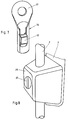
- FIG. 7 shows a further embodiment of the fastening device, in which only one leg 12 is provided, as it were.
- the leg 12 is part of a fastening body 36, which is designed like a sleeve and is intended in its interior for receiving the wire strut, not shown.
- the leg 12 rests resiliently on part of the surface of the wire strut and thus realizes a single force threshold.
- the fastening body 36 has an eye 37, by means of which it can be connected, for example riveted, to an ear 6 of a fastening bridge 5.
- the fastening device is primarily used on the fender side. But it can also be used on the fork side or in the intermediate area.
Landscapes
- Engineering & Computer Science (AREA)
- General Engineering & Computer Science (AREA)
- Mechanical Engineering (AREA)
- Clamps And Clips (AREA)
- Axle Suspensions And Sidecars For Cycles (AREA)
Applications Claiming Priority (2)
| Application Number | Priority Date | Filing Date | Title |
|---|---|---|---|
| DE4241371 | 1992-12-09 | ||
| DE19924241371 DE4241371A1 (de) | 1992-12-09 | 1992-12-09 | Befestigungsvorrichtung für ein Schutzblech |
Publications (1)
| Publication Number | Publication Date |
|---|---|
| EP0601409A1 true EP0601409A1 (fr) | 1994-06-15 |
Family
ID=6474723
Family Applications (1)
| Application Number | Title | Priority Date | Filing Date |
|---|---|---|---|
| EP93119040A Withdrawn EP0601409A1 (fr) | 1992-12-09 | 1993-11-25 | Dispositif de fixation d'un garde-boue |
Country Status (2)
| Country | Link |
|---|---|
| EP (1) | EP0601409A1 (fr) |
| DE (1) | DE4241371A1 (fr) |
Cited By (2)
| Publication number | Priority date | Publication date | Assignee | Title |
|---|---|---|---|---|
| NL1010008C2 (nl) * | 1998-09-04 | 2000-03-07 | Hapro International B V | Bevestigingssysteem alsmede koffer voorzien van een dergelijk bevestigingssysteem. |
| GB2383314A (en) * | 2001-12-18 | 2003-06-25 | Spencer Mfg Ltd | Connecting device for a mudguard |
Families Citing this family (3)
| Publication number | Priority date | Publication date | Assignee | Title |
|---|---|---|---|---|
| DE4426918C2 (de) * | 1994-07-29 | 1997-05-15 | Esge Marby Gmbh & Co | Schutzblechanordnung |
| DE29607628U1 (de) * | 1996-04-26 | 1996-07-11 | Sks Metaplast Scheffer Klute | Einrichtung zur Befestigung von Streben eines Radschützers eines Fahrrads |
| DE20008005U1 (de) | 2000-05-05 | 2000-07-20 | Sks Metaplast Scheffer Klute | Befestigungseinrichtung für einen Radschützer |
Citations (5)
| Publication number | Priority date | Publication date | Assignee | Title |
|---|---|---|---|---|
| GB626438A (en) * | 1947-08-28 | 1949-07-14 | Bluemel Brothers Ltd | A new or improved bicycle mudguard stay |
| GB838163A (en) * | 1958-01-14 | 1960-06-22 | Bluemel Brothers Ltd | New or improved means for securing a mudguard to cycle stays |
| GB1460948A (en) * | 1974-04-30 | 1977-01-06 | Davitance Ltd | Spring clips |
| DE8712620U1 (fr) * | 1987-09-18 | 1987-10-29 | Georg Kimmel Gmbh & Co Kg, 4050 Moenchengladbach, De | |
| DE9109377U1 (fr) * | 1991-07-30 | 1992-01-02 | Elbracht, Horst, 4800 Bielefeld, De |
Family Cites Families (1)
| Publication number | Priority date | Publication date | Assignee | Title |
|---|---|---|---|---|
| DE1831526U (de) * | 1961-02-27 | 1961-05-18 | C O Niessen Fa | Strebenhalter, insbesondere fuer fahrradschutzbleche. |
-
1992
- 1992-12-09 DE DE19924241371 patent/DE4241371A1/de not_active Ceased
-
1993
- 1993-11-25 EP EP93119040A patent/EP0601409A1/fr not_active Withdrawn
Patent Citations (5)
| Publication number | Priority date | Publication date | Assignee | Title |
|---|---|---|---|---|
| GB626438A (en) * | 1947-08-28 | 1949-07-14 | Bluemel Brothers Ltd | A new or improved bicycle mudguard stay |
| GB838163A (en) * | 1958-01-14 | 1960-06-22 | Bluemel Brothers Ltd | New or improved means for securing a mudguard to cycle stays |
| GB1460948A (en) * | 1974-04-30 | 1977-01-06 | Davitance Ltd | Spring clips |
| DE8712620U1 (fr) * | 1987-09-18 | 1987-10-29 | Georg Kimmel Gmbh & Co Kg, 4050 Moenchengladbach, De | |
| DE9109377U1 (fr) * | 1991-07-30 | 1992-01-02 | Elbracht, Horst, 4800 Bielefeld, De |
Cited By (5)
| Publication number | Priority date | Publication date | Assignee | Title |
|---|---|---|---|---|
| NL1010008C2 (nl) * | 1998-09-04 | 2000-03-07 | Hapro International B V | Bevestigingssysteem alsmede koffer voorzien van een dergelijk bevestigingssysteem. |
| EP0983903A1 (fr) * | 1998-09-04 | 2000-03-08 | Hapro International B.V. | Dispositif pour fixer un coffre de toit à un cadre, et coffre de toit équipé d'un tel dispositif |
| US6296161B1 (en) | 1998-09-04 | 2001-10-02 | Hapro International B.V. | Fastening system as well as a suitcase provided with such a fastening system |
| GB2383314A (en) * | 2001-12-18 | 2003-06-25 | Spencer Mfg Ltd | Connecting device for a mudguard |
| GB2383314B (en) * | 2001-12-18 | 2005-02-16 | Spencer Mfg Ltd | Connecting device |
Also Published As
| Publication number | Publication date |
|---|---|
| DE4241371A1 (de) | 1994-06-16 |
Similar Documents
| Publication | Publication Date | Title |
|---|---|---|
| DE60117386T2 (de) | Verbesserte radmutteranordnung | |
| EP1541882B1 (fr) | Elément de fixation | |
| DE3001414C2 (de) | Verbindungsanordnung | |
| EP0854791B1 (fr) | Dispositif pour fixer de maniere amovible une roue supplementaire sur la roue d'un vehicule | |
| DE19929966A1 (de) | Sicherungssystem für einen Bolzen und eine Mutter | |
| DE102005033810A1 (de) | Lenker für eine Fahrzeugradaufhängung mit einer Sollbruchstelle | |
| DE4437658C1 (de) | Bremsdruckstange | |
| WO2008101593A1 (fr) | Axe de blocage rapide | |
| EP0694469B1 (fr) | Garde-boue | |
| EP1151911A2 (fr) | Dispositif de fixation pour garde-boue | |
| DE19516425B4 (de) | Einrichtung zur lösbaren Befestigung einer Achse | |
| EP0529252A2 (fr) | Ecrou pour arbre | |
| DE3224589A1 (de) | Gepaecktraeger fuer ein zweirad | |
| EP0601409A1 (fr) | Dispositif de fixation d'un garde-boue | |
| DE602005000489T2 (de) | Hebelbetätigbare Klemmvorrichtung zum Befestigen von einem Anti-Gleit-System an der Felge von einem Fahrzeugrad | |
| EP2243642B1 (fr) | Dispositif de protection contre le glissement doté d'une liaison de jantes | |
| DE102008029136A1 (de) | Fahrradachsenanordnung | |
| EP3889448B1 (fr) | Élément de fixation | |
| EP0853034A2 (fr) | Dispositif anti-vol pour bicyclettes | |
| DE19701371B4 (de) | Einrichtung zur Befestigung eines Reserverades in einer Reserveradmulde eines Kraftfahrzeugs | |
| DE4212180C2 (de) | Anordnung zur Befestigung eines Fahrwerkteils | |
| DE202005005501U1 (de) | Schnellspannmutter | |
| DE202005009467U1 (de) | Vorrichtung zum Lösen eines in einer Aufnahmebohrung festsitzenden Bolzens | |
| DE3910644C2 (fr) | ||
| EP2860091B1 (fr) | Fixation de rétroviseur pour deux roues |
Legal Events
| Date | Code | Title | Description |
|---|---|---|---|
| PUAI | Public reference made under article 153(3) epc to a published international application that has entered the european phase |
Free format text: ORIGINAL CODE: 0009012 |
|
| 17P | Request for examination filed |
Effective date: 19940419 |
|
| AK | Designated contracting states |
Kind code of ref document: A1 Designated state(s): AT BE CH DE DK ES FR GB IE IT LI NL PT SE |
|
| 17Q | First examination report despatched |
Effective date: 19950327 |
|
| STAA | Information on the status of an ep patent application or granted ep patent |
Free format text: STATUS: THE APPLICATION IS DEEMED TO BE WITHDRAWN |
|
| 18D | Application deemed to be withdrawn |
Effective date: 19950808 |