EP0601239A1 - Gerät zum Antrieb eines an einem schwenkbaren Teil angeordneten Werkzeugs - Google Patents
Gerät zum Antrieb eines an einem schwenkbaren Teil angeordneten Werkzeugs Download PDFInfo
- Publication number
- EP0601239A1 EP0601239A1 EP92203834A EP92203834A EP0601239A1 EP 0601239 A1 EP0601239 A1 EP 0601239A1 EP 92203834 A EP92203834 A EP 92203834A EP 92203834 A EP92203834 A EP 92203834A EP 0601239 A1 EP0601239 A1 EP 0601239A1
- Authority
- EP
- European Patent Office
- Prior art keywords
- shaft
- stationary
- pivotable part
- wheel
- axis
- Prior art date
- Legal status (The legal status is an assumption and is not a legal conclusion. Google has not performed a legal analysis and makes no representation as to the accuracy of the status listed.)
- Granted
Links
Images
Classifications
-
- E—FIXED CONSTRUCTIONS
- E02—HYDRAULIC ENGINEERING; FOUNDATIONS; SOIL SHIFTING
- E02F—DREDGING; SOIL-SHIFTING
- E02F3/00—Dredgers; Soil-shifting machines
- E02F3/04—Dredgers; Soil-shifting machines mechanically-driven
- E02F3/88—Dredgers; Soil-shifting machines mechanically-driven with arrangements acting by a sucking or forcing effect, e.g. suction dredgers
- E02F3/90—Component parts, e.g. arrangement or adaptation of pumps
- E02F3/905—Manipulating or supporting suction pipes or ladders; Mechanical supports or floaters therefor; pipe joints for suction pipes
-
- F—MECHANICAL ENGINEERING; LIGHTING; HEATING; WEAPONS; BLASTING
- F16—ENGINEERING ELEMENTS AND UNITS; GENERAL MEASURES FOR PRODUCING AND MAINTAINING EFFECTIVE FUNCTIONING OF MACHINES OR INSTALLATIONS; THERMAL INSULATION IN GENERAL
- F16H—GEARING
- F16H1/00—Toothed gearings for conveying rotary motion
- F16H1/006—Toothed gearings for conveying rotary motion the driving and driven axes being designed to assume variable positions relative to one another during operation
-
- Y—GENERAL TAGGING OF NEW TECHNOLOGICAL DEVELOPMENTS; GENERAL TAGGING OF CROSS-SECTIONAL TECHNOLOGIES SPANNING OVER SEVERAL SECTIONS OF THE IPC; TECHNICAL SUBJECTS COVERED BY FORMER USPC CROSS-REFERENCE ART COLLECTIONS [XRACs] AND DIGESTS
- Y10—TECHNICAL SUBJECTS COVERED BY FORMER USPC
- Y10T—TECHNICAL SUBJECTS COVERED BY FORMER US CLASSIFICATION
- Y10T74/00—Machine element or mechanism
- Y10T74/19—Gearing
- Y10T74/19502—Pivotally supported
- Y10T74/19521—Bevel
-
- Y—GENERAL TAGGING OF NEW TECHNOLOGICAL DEVELOPMENTS; GENERAL TAGGING OF CROSS-SECTIONAL TECHNOLOGIES SPANNING OVER SEVERAL SECTIONS OF THE IPC; TECHNICAL SUBJECTS COVERED BY FORMER USPC CROSS-REFERENCE ART COLLECTIONS [XRACs] AND DIGESTS
- Y10—TECHNICAL SUBJECTS COVERED BY FORMER USPC
- Y10T—TECHNICAL SUBJECTS COVERED BY FORMER US CLASSIFICATION
- Y10T74/00—Machine element or mechanism
- Y10T74/19—Gearing
- Y10T74/19642—Directly cooperating gears
- Y10T74/1966—Intersecting axes
- Y10T74/19665—Bevel gear type
-
- Y—GENERAL TAGGING OF NEW TECHNOLOGICAL DEVELOPMENTS; GENERAL TAGGING OF CROSS-SECTIONAL TECHNOLOGIES SPANNING OVER SEVERAL SECTIONS OF THE IPC; TECHNICAL SUBJECTS COVERED BY FORMER USPC CROSS-REFERENCE ART COLLECTIONS [XRACs] AND DIGESTS
- Y10—TECHNICAL SUBJECTS COVERED BY FORMER USPC
- Y10T—TECHNICAL SUBJECTS COVERED BY FORMER US CLASSIFICATION
- Y10T74/00—Machine element or mechanism
- Y10T74/19—Gearing
- Y10T74/19642—Directly cooperating gears
- Y10T74/19674—Spur and bevel
Definitions
- the invention relates to a device for driving a tool positioned on a pivotable part, said device comprising a combustion engine or the like and coupling means between this engine and the tool.
- a pump which is positioned on a so-called ladder of a suction dredger, said ladder being pivotably mounted to the dredger vessel.
- the pump serves for suction of material from the bottom of a water and for pressing it away into the vessel or to another place.
- the engine for driving the pump can also be arranged on the ladder, to wit at its upper end, so at the greatest possible distance above the water surface as possible.
- a shaft for transmitting the power produced by the motor to the pump can extend along the ladder between the motor and the pump.
- transmitting the power is effected in a direct and thus simple way, but operating the motor and the supply of fuel thereto is laborious.
- the ladder will be exposed to loads as well as vibrations exerted theron by the motor.
- the ladder will have to be dimensioned with a view to this and thus be made heavier, by which pivoting it will also require more power. It is also possible that with fierce beating of the waves, water can sweep over the motor.
- the disadvangtage arises that the position of the motor experiences changes on pivoting the ladder, by which the lubrication of the motor can be endangered. This will in particular occur in larger engines, so with a relatively high power of the pump.
- the device is designed such, that the motor is arranged stationary and such, that the extension of the axis of the motor drive shaft crosses the pivot axis of the pivotable part and is square thereto, the motor drive shaft driving a transmission shaft by means of a bevel gear or crown gear transmission, said transmission shaft being pivotably supported by the pivotable part in such a way, that the extension of the axis of the transmission shaft likewise crosses the pivot axis of the pivotable part and is square thereto, while the transmission shaft runs substantially parallel to the longitudinal axis of the pivotable part, and on pivoting this will be in a plane in which the motor drive shaft will be positioned as well, a wheel of the bevel gear or crown gear transmission being mounted on a wheel shaft, the axis of which coincides with the pivot axis of the pivotable part, said wheel being engaged with the wheels mounted on the motor drive shaft and the transmission shaft respectively, an output shaft being mounted on the pivotable part and running parallel to or in line with the transmission shaft, said output shaft running to the tool to be
- a stationary arrangement of the motor brings considerable advantages, while the tool, located on the pivotable part, is yet drivable through a relatively simple transmission.
- a gear transmission can be mounted between the transmission shaft and the output shaft, through which, if required, the speeds of the shafts can differ from each other.
- the transmission ratio between the motor drive shaft and the output shaft can further also be controlled by adjustment of the bevel gear wheels c.q. crown gear wheels, or by mounting additional wheels in the input or output section of the transmission.
- a housing consisting of at least two sections, to wit a first stationary section and a second section which can move along with the pivotable part, with the sections of the housing having been sealed in relation to each other.
- the wheel directly driven by the motor drive shaft has been mounted on an input shaft, which is supported by the stationary section of the housing, with an intermediate shaft having been mounted between the input shaft and the motor drive shaft, said intermediate shaft being able to experience an extension and being coupled to both shafts by cardan joints.
- the stationary section of the housing will substantially be located within the second section thereof and has been provided with two bearings, the axes of which being in line and coinciding with the axis of the pivot shaft of the pivotable part and with the axes of two bearings accommodated in the second housing section and which bearings serve for supporting the wheel shaft, the stationary housing section, at a distance from the axes of said bearings and outside of the second housing section, having been pivotally connected to at least one arm, which in turn has been pivotally connected to a stationary part.
- the second housing section can only perform a rotating movement in relation to the stationary section, so that the wheels of the bevel gear or crown gear transmission will always take the correct position in relation to each other. Through this, the occurring wear can be limited.
- the wheel shaft in the stationary housing section will be supported in a bush being part of the stationary housing section and which projects outwardly through an elongated slot in the wall of the second housing section and has been connected to the arm extending between the stationary housing section and a stationary part, in which this wall of the second housing section, provided with the slot, has a bent shape, the centre of curvature of which coinciding with the axis of the pivot shaft of the pivotable part.
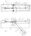
- 1 indicates a dredger vessel or pontoon, on which the ladder 2 has been pivotably fastened in the pivot points 3.
- the pump 4 has been fastened to the ladder 2 and is to be driven by the motor 5.
- the motor 5 has been arranged stationary on the deck of the vessel 1.
- the motor 5 has the motor drive shaft 6, which has been connected to the intermediate shaft 8 by a cardan joint 7.
- the intermediate shaft 8 can have a telescopic part not further indicated and has its other end connected to the wheel shaft 9 by means of a cardan joint 7.
- the wheel shaft 9 is supported by the bearings 10 in a bush 11, which is part of a stationary section 12 of the housing 13.
- the housing 13 further comprises the section 14, which in a way yet to be described further is pivotably connected to the housing section 12.
- the housing section 12 has been coupled to the ladder 2 in a way not further indicated.
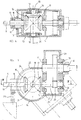
- the wheel shaft 9 has been provided with the bevel gear wheel 15, which is in engagement with a bevel gear wheel 16, which in turn is in engagement with the bevel gear wheel 17.
- the bevel gear wheel 16 has been mounted on the shaft 18, which is supported in the housing section 14 by means of the bearings 19.
- bearings 20 are present between the housing sections 12 and 14, so that the housing sections 12 and 14 are pivotably connected to each other.
- the axes 21 of the wheel shaft 18 and of the bearings 19 and 20 coincide with the pivot axis 22 of the ladder 2 and thus with the axes of the pivot points 3.
- the bush 11 of the stationary housing section 12 has further been connected to a part stationary in relation to the motor 5, so to the vessel 1 as well.
- the bush 11 extends through a slot 24 in the partially cilindrical wall 25 of the housing section 14.
- the bevel wheel 17 has been mounted on the transmission shaft 26, which is supported in the housing section 14 by means of the bearings 27.
- a gear wheel 28 is located being in engagement with a gear wheel 29, mounted on the output shaft 30, which is supported in the housing section 14 by means of the bearings 31.
- all bevel gear wheels 15, 16 and 17 and the gear wheels 28 and 29 are located within the housing 13, so that dirt is prevented from getting between the wheels and the wheels can be lubricated.
Landscapes
- Engineering & Computer Science (AREA)
- General Engineering & Computer Science (AREA)
- Mechanical Engineering (AREA)
- Mining & Mineral Resources (AREA)
- Civil Engineering (AREA)
- Structural Engineering (AREA)
- Gear Transmission (AREA)
Priority Applications (4)
| Application Number | Priority Date | Filing Date | Title |
|---|---|---|---|
| AU30009/92A AU656044B2 (en) | 1992-12-09 | 1992-12-09 | Device for driving a tool positioned on a pivotable part |
| DE1992618440 DE69218440T2 (de) | 1992-12-09 | 1992-12-09 | Gerät zum Antrieb eines an einem schwenkbaren Teil angeordneten Werkzeugs |
| EP92203834A EP0601239B1 (de) | 1992-12-09 | 1992-12-09 | Gerät zum Antrieb eines an einem schwenkbaren Teil angeordneten Werkzeugs |
| US07/987,723 US5327794A (en) | 1992-12-09 | 1992-12-09 | Device for driving a tool positioned on a pivotable part |
Applications Claiming Priority (3)
| Application Number | Priority Date | Filing Date | Title |
|---|---|---|---|
| AU30009/92A AU656044B2 (en) | 1992-12-09 | 1992-12-09 | Device for driving a tool positioned on a pivotable part |
| EP92203834A EP0601239B1 (de) | 1992-12-09 | 1992-12-09 | Gerät zum Antrieb eines an einem schwenkbaren Teil angeordneten Werkzeugs |
| US07/987,723 US5327794A (en) | 1992-12-09 | 1992-12-09 | Device for driving a tool positioned on a pivotable part |
Publications (2)
| Publication Number | Publication Date |
|---|---|
| EP0601239A1 true EP0601239A1 (de) | 1994-06-15 |
| EP0601239B1 EP0601239B1 (de) | 1997-03-19 |
Family
ID=27153280
Family Applications (1)
| Application Number | Title | Priority Date | Filing Date |
|---|---|---|---|
| EP92203834A Expired - Lifetime EP0601239B1 (de) | 1992-12-09 | 1992-12-09 | Gerät zum Antrieb eines an einem schwenkbaren Teil angeordneten Werkzeugs |
Country Status (3)
| Country | Link |
|---|---|
| US (1) | US5327794A (de) |
| EP (1) | EP0601239B1 (de) |
| AU (1) | AU656044B2 (de) |
Families Citing this family (2)
| Publication number | Priority date | Publication date | Assignee | Title |
|---|---|---|---|---|
| WO2007056251A2 (en) * | 2005-11-04 | 2007-05-18 | Robert Bosch Gmbh | Articulating drill with optical speed control and method of operation |
| DE102007018882A1 (de) * | 2007-04-19 | 2008-10-23 | Arthur Habermann Gmbh & Co. Kg | Schwimmbagger |
Citations (7)
| Publication number | Priority date | Publication date | Assignee | Title |
|---|---|---|---|---|
| FR332307A (fr) * | 1903-05-23 | 1903-10-26 | Georges Desire Lacroix | Appareils de succion pour dragues hydrauliques |
| FR363002A (fr) * | 1906-02-05 | 1906-07-19 | Louis Coiseau | Dragueur-aspirateur |
| US2507844A (en) * | 1946-05-03 | 1950-05-16 | Beaumont B Wright | Motorboat steering and propulsion mechanism |
| US2902967A (en) * | 1956-06-01 | 1959-09-08 | Arthur W Wanzer | Outboard propeller mechanism for vessels |
| US3051120A (en) * | 1958-05-16 | 1962-08-28 | Elizabeth V Standal | Inboard outboard drive mechanism for boats |
| US3094097A (en) * | 1958-03-18 | 1963-06-18 | Floyd P Ellzey | Inboard-outboard boat propulsion unit |
| US3362246A (en) * | 1964-07-14 | 1968-01-09 | Volvo Penta Ab | Gear housing on propeller assembly for boats |
Family Cites Families (11)
| Publication number | Priority date | Publication date | Assignee | Title |
|---|---|---|---|---|
| US1768472A (en) * | 1930-06-24 | Mechanical driving means por concrete mixers | ||
| US638883A (en) * | 1899-05-09 | 1899-12-12 | Atlantic Gulf And Pacific Company | Dredger. |
| US2050497A (en) * | 1934-12-15 | 1936-08-11 | Jack C Sanford | Self-aligning drive shaft |
| DE662941C (de) * | 1935-08-16 | 1938-07-25 | Aude & Reipert | Antriebsvorrichtung fuer den Fliehkraftregler von Eisenbahnbremsen |
| US2235427A (en) * | 1940-06-19 | 1941-03-18 | Condenser Service & Engineerin | Universal drive |
| US2509092A (en) * | 1946-11-07 | 1950-05-23 | Richard J Faulkner | Tractor supported and driven saw mechanism |
| GB1137440A (en) * | 1967-05-12 | 1968-12-18 | Rotary Hoes Ltd | Drive transmission gear box |
| US4296654A (en) * | 1979-08-20 | 1981-10-27 | Mercer Albert E | Adjustable angled socket wrench extension |
| JPH0659635B2 (ja) * | 1981-10-07 | 1994-08-10 | 株式会社日立製作所 | ロボツト手首 |
| JPS6080591A (ja) * | 1983-10-05 | 1985-05-08 | 株式会社日立製作所 | マニプレ−タ |
| SU1289678A1 (ru) * | 1985-06-19 | 1987-02-15 | Донецкий политехнический институт | Механическа рука робота |
-
1992
- 1992-12-09 AU AU30009/92A patent/AU656044B2/en not_active Expired
- 1992-12-09 US US07/987,723 patent/US5327794A/en not_active Expired - Lifetime
- 1992-12-09 EP EP92203834A patent/EP0601239B1/de not_active Expired - Lifetime
Patent Citations (7)
| Publication number | Priority date | Publication date | Assignee | Title |
|---|---|---|---|---|
| FR332307A (fr) * | 1903-05-23 | 1903-10-26 | Georges Desire Lacroix | Appareils de succion pour dragues hydrauliques |
| FR363002A (fr) * | 1906-02-05 | 1906-07-19 | Louis Coiseau | Dragueur-aspirateur |
| US2507844A (en) * | 1946-05-03 | 1950-05-16 | Beaumont B Wright | Motorboat steering and propulsion mechanism |
| US2902967A (en) * | 1956-06-01 | 1959-09-08 | Arthur W Wanzer | Outboard propeller mechanism for vessels |
| US3094097A (en) * | 1958-03-18 | 1963-06-18 | Floyd P Ellzey | Inboard-outboard boat propulsion unit |
| US3051120A (en) * | 1958-05-16 | 1962-08-28 | Elizabeth V Standal | Inboard outboard drive mechanism for boats |
| US3362246A (en) * | 1964-07-14 | 1968-01-09 | Volvo Penta Ab | Gear housing on propeller assembly for boats |
Also Published As
| Publication number | Publication date |
|---|---|
| US5327794A (en) | 1994-07-12 |
| EP0601239B1 (de) | 1997-03-19 |
| AU3000992A (en) | 1994-06-23 |
| AU656044B2 (en) | 1995-01-19 |
Similar Documents
| Publication | Publication Date | Title |
|---|---|---|
| US4939854A (en) | Rotary trenching machine | |
| AU738396B2 (en) | Windshield wiper assembly having a variable speed drive mechanism | |
| EP0601239A1 (de) | Gerät zum Antrieb eines an einem schwenkbaren Teil angeordneten Werkzeugs | |
| CA1220672A (en) | Water pump location for marine propulsion device | |
| EP0876932B1 (de) | Kraftübertragungseinrichtung für eine Arbeitsmachine | |
| KR900004464A (ko) | 산업용 로보트 | |
| US11612115B2 (en) | Stump cutter drive system | |
| KR970001660B1 (ko) | 수직다관절 로보트 | |
| US5707202A (en) | Material handling machine | |
| JP3455242B2 (ja) | しゅんせつ工具やポンプを駆動する装置 | |
| EP3918909B1 (de) | Antriebssystem für stumpfschneider | |
| RU2171194C1 (ru) | Шагающая опора для многоопорных транспортно-погрузочных средств повышенной проходимости | |
| US20210339838A1 (en) | Water-jet propulsion unit and a boat | |
| US4964823A (en) | Stern drive lift and trim system | |
| GB2166033A (en) | Mowing machine | |
| FR2789461A1 (fr) | Agencement d'un joint universel a croisillon et d'une roue dentee pour une transmission | |
| US11612114B2 (en) | Stump cutter drive system | |
| FI92989C (fi) | Kampiakselivaihteisto | |
| NL9101989A (nl) | Inrichting voor het aandrijven van een, op een verzwenkbaar onderdeel geplaatst, werktuig. | |
| CH622321A5 (de) | ||
| JPH0347480Y2 (de) | ||
| SU1121363A1 (ru) | Роторный траншейный экскаватор | |
| JPH0713464Y2 (ja) | 軸駆動式モアのギヤボックス | |
| JPS5912291Y2 (ja) | 全旋回作業車の旋回台構造 | |
| CN118176150A (zh) | 用于船只的动力系统 |
Legal Events
| Date | Code | Title | Description |
|---|---|---|---|
| PUAI | Public reference made under article 153(3) epc to a published international application that has entered the european phase |
Free format text: ORIGINAL CODE: 0009012 |
|
| AK | Designated contracting states |
Kind code of ref document: A1 Designated state(s): BE DE FR GB IT NL |
|
| 17P | Request for examination filed |
Effective date: 19940530 |
|
| 17Q | First examination report despatched |
Effective date: 19951016 |
|
| GRAG | Despatch of communication of intention to grant |
Free format text: ORIGINAL CODE: EPIDOS AGRA |
|
| GRAH | Despatch of communication of intention to grant a patent |
Free format text: ORIGINAL CODE: EPIDOS IGRA |
|
| GRAH | Despatch of communication of intention to grant a patent |
Free format text: ORIGINAL CODE: EPIDOS IGRA |
|
| GRAA | (expected) grant |
Free format text: ORIGINAL CODE: 0009210 |
|
| AK | Designated contracting states |
Kind code of ref document: B1 Designated state(s): BE DE FR GB IT NL |
|
| PG25 | Lapsed in a contracting state [announced via postgrant information from national office to epo] |
Ref country code: BE Effective date: 19970319 |
|
| ITF | It: translation for a ep patent filed | ||
| REF | Corresponds to: |
Ref document number: 69218440 Country of ref document: DE Date of ref document: 19970424 |
|
| ET | Fr: translation filed | ||
| PLBE | No opposition filed within time limit |
Free format text: ORIGINAL CODE: 0009261 |
|
| 26N | No opposition filed | ||
| REG | Reference to a national code |
Ref country code: GB Ref legal event code: IF02 |
|
| NLS | Nl: assignments of ep-patents |
Owner name: IHC HOLLAND IE B.V. Effective date: 20060306 |
|
| REG | Reference to a national code |
Ref country code: GB Ref legal event code: 732E |
|
| REG | Reference to a national code |
Ref country code: FR Ref legal event code: TP |
|
| PGFP | Annual fee paid to national office [announced via postgrant information from national office to epo] |
Ref country code: IT Payment date: 20101217 Year of fee payment: 19 |
|
| PGFP | Annual fee paid to national office [announced via postgrant information from national office to epo] |
Ref country code: FR Payment date: 20120105 Year of fee payment: 20 Ref country code: NL Payment date: 20111220 Year of fee payment: 20 |
|
| PGFP | Annual fee paid to national office [announced via postgrant information from national office to epo] |
Ref country code: DE Payment date: 20120229 Year of fee payment: 20 |
|
| PGFP | Annual fee paid to national office [announced via postgrant information from national office to epo] |
Ref country code: GB Payment date: 20120103 Year of fee payment: 20 |
|
| REG | Reference to a national code |
Ref country code: DE Ref legal event code: R071 Ref document number: 69218440 Country of ref document: DE |
|
| REG | Reference to a national code |
Ref country code: DE Ref legal event code: R071 Ref document number: 69218440 Country of ref document: DE |
|
| REG | Reference to a national code |
Ref country code: NL Ref legal event code: V4 Effective date: 20121209 |
|
| REG | Reference to a national code |
Ref country code: GB Ref legal event code: PE20 Expiry date: 20121208 |
|
| PG25 | Lapsed in a contracting state [announced via postgrant information from national office to epo] |
Ref country code: GB Free format text: LAPSE BECAUSE OF EXPIRATION OF PROTECTION Effective date: 20121208 |