EP0601136B1 - Ineinandergreifende sitzverstellvorrichtung mit kompensationsstange - Google Patents
Ineinandergreifende sitzverstellvorrichtung mit kompensationsstange Download PDFInfo
- Publication number
- EP0601136B1 EP0601136B1 EP93903751A EP93903751A EP0601136B1 EP 0601136 B1 EP0601136 B1 EP 0601136B1 EP 93903751 A EP93903751 A EP 93903751A EP 93903751 A EP93903751 A EP 93903751A EP 0601136 B1 EP0601136 B1 EP 0601136B1
- Authority
- EP
- European Patent Office
- Prior art keywords
- seat
- seat bracket
- riser
- links
- motion
- Prior art date
- Legal status (The legal status is an assumption and is not a legal conclusion. Google has not performed a legal analysis and makes no representation as to the accuracy of the status listed.)
- Expired - Lifetime
Links
Images


Classifications
-
- B—PERFORMING OPERATIONS; TRANSPORTING
- B60—VEHICLES IN GENERAL
- B60N—SEATS SPECIALLY ADAPTED FOR VEHICLES; VEHICLE PASSENGER ACCOMMODATION NOT OTHERWISE PROVIDED FOR
- B60N2/00—Seats specially adapted for vehicles; Arrangement or mounting of seats in vehicles
- B60N2/02—Seats specially adapted for vehicles; Arrangement or mounting of seats in vehicles the seat or part thereof being movable, e.g. adjustable
- B60N2/04—Seats specially adapted for vehicles; Arrangement or mounting of seats in vehicles the seat or part thereof being movable, e.g. adjustable the whole seat being movable
- B60N2/045—Longitudinal adjustment by means of articulated rods supporting the seat, e.g. parallelogram mechanisms
-
- B—PERFORMING OPERATIONS; TRANSPORTING
- B60—VEHICLES IN GENERAL
- B60N—SEATS SPECIALLY ADAPTED FOR VEHICLES; VEHICLE PASSENGER ACCOMMODATION NOT OTHERWISE PROVIDED FOR
- B60N2/00—Seats specially adapted for vehicles; Arrangement or mounting of seats in vehicles
- B60N2/02—Seats specially adapted for vehicles; Arrangement or mounting of seats in vehicles the seat or part thereof being movable, e.g. adjustable
- B60N2/04—Seats specially adapted for vehicles; Arrangement or mounting of seats in vehicles the seat or part thereof being movable, e.g. adjustable the whole seat being movable
- B60N2/16—Seats specially adapted for vehicles; Arrangement or mounting of seats in vehicles the seat or part thereof being movable, e.g. adjustable the whole seat being movable height-adjustable
- B60N2/1605—Seats specially adapted for vehicles; Arrangement or mounting of seats in vehicles the seat or part thereof being movable, e.g. adjustable the whole seat being movable height-adjustable characterised by the cinematic
- B60N2/161—Rods
- B60N2/1615—Parallelogram-like structure
-
- B—PERFORMING OPERATIONS; TRANSPORTING
- B60—VEHICLES IN GENERAL
- B60N—SEATS SPECIALLY ADAPTED FOR VEHICLES; VEHICLE PASSENGER ACCOMMODATION NOT OTHERWISE PROVIDED FOR
- B60N2/00—Seats specially adapted for vehicles; Arrangement or mounting of seats in vehicles
- B60N2/02—Seats specially adapted for vehicles; Arrangement or mounting of seats in vehicles the seat or part thereof being movable, e.g. adjustable
- B60N2/04—Seats specially adapted for vehicles; Arrangement or mounting of seats in vehicles the seat or part thereof being movable, e.g. adjustable the whole seat being movable
- B60N2/16—Seats specially adapted for vehicles; Arrangement or mounting of seats in vehicles the seat or part thereof being movable, e.g. adjustable the whole seat being movable height-adjustable
- B60N2/1685—Seats specially adapted for vehicles; Arrangement or mounting of seats in vehicles the seat or part thereof being movable, e.g. adjustable the whole seat being movable height-adjustable characterised by a lock
-
- B—PERFORMING OPERATIONS; TRANSPORTING
- B60—VEHICLES IN GENERAL
- B60N—SEATS SPECIALLY ADAPTED FOR VEHICLES; VEHICLE PASSENGER ACCOMMODATION NOT OTHERWISE PROVIDED FOR
- B60N2/00—Seats specially adapted for vehicles; Arrangement or mounting of seats in vehicles
- B60N2/02—Seats specially adapted for vehicles; Arrangement or mounting of seats in vehicles the seat or part thereof being movable, e.g. adjustable
- B60N2/04—Seats specially adapted for vehicles; Arrangement or mounting of seats in vehicles the seat or part thereof being movable, e.g. adjustable the whole seat being movable
- B60N2/16—Seats specially adapted for vehicles; Arrangement or mounting of seats in vehicles the seat or part thereof being movable, e.g. adjustable the whole seat being movable height-adjustable
- B60N2/169—Stepwise movement mechanisms, e.g. ratchets
Definitions
- This invention relates to mechanisms for moving a seat bracket and the seat attached forward and backwards in relation to a frame. Specifically this invention finds application in seats for a vehicle.
- U.S. Patent 4,807,932 issued on February 28, 1989 to Kia Motors describes a device for moving an automobile seat back and forth including legs pivotable to the frame which moves the seat along an arcuate path.
- US-3,006,594 discloses a seat linkage powered by reversible electric motors.
- a preferably compact adjustment mechanism for a seat which includes a linkage system including a compensating link to compensate for the arcuate motion of the primary links of the mechanism rendering the final longitudinal motion of the seat as substantially linear within the range of motion of the seat.
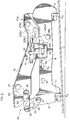
- FIG. 1 there is illustrated in perspective view a vehicle seat S including a seat back S1 and a seat S2.
- the seat S2 is attached to a seat bracket B which is pivotably engaged with a riser R anchored to the floor of a vehicle.
- pins P1 and P2 are provided for the latching, via latch mechanisms L1 and L2, of the riser R and therefor the seat S2 to the vehicle.
- the pins or strikers P1 and P2 are often recessed within opening or wells provided with the floor of a vehicle such as a van.
- a seat adjuster 10 is provided at the front and rear and on both sides of the seat S2, to provide the longitudinal for and aft motion of the seat S2 in relation to the stationary riser R in the directions F and A respectively.
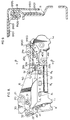
- a resillently biased latching mechanism 50 operative via handle H, in cooperation with openings B1 of the seat bracket and R1, R2 and R3 provided with the riser allow for the motion of the seat to and from these predefined comfort positions.
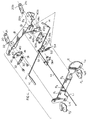
- the mechanisms 10 and 10a disposed proximate the front and rear of the seat bracket B provide for the substantially linear movement thereof with respect to the riser R via the cooperative pivotal operation of the links 20, 30, and 40 and 20a, 30a, and 40a.
- the links 40 and 40a pivot from the riser R at pivots 41 and 41a.
- the links 20 and 20a pivot from the seat bracket B at 21 and 21a respectively and from proximate the center 22 and 22a of link 40 and 40a.
- the links 30 and 30a pivot from the seat bracket B at 31 and 31a respectively and from proximate the free ends 32 and 32a of link 40 and 40a.
- the seat bracket and riser may be formed by conventional stamping techniques or the like, wherein the necessary features such as mounting opening for seat S2, the latch positions R1, R2 and R3, the slotted latch portions L1 and L2, and the openings for the pivots are provided.
- the supplementary portion B4 (as best seen in Figure 7) of seat bracket B may be affixed with B by conventional methods such as welding, fastening or the like.
- the latch 50 is resiliently biased via spring 53 and operative via the handle H causing portion H1 of the handle extension to engage near end 51 of the latch 50 and thereby move the detent 52 out of openings B1, and R3 as illustrated and therefore allow motion of the seat in the forward direction F by the operator.
- the seat bracket B is free to move as urged by an occupant in relation to the stationary riser R, the pairs of links 20, 20a, 30, 30a and 40, 40a will pivot over described cooperative paths, as best seen in Figure 6 which result in the movement of the seat S2 in relation to the floor C of Figure 2 in a substantially linear path.
- the seat adjuster 10 will maintain the seat bracket B a substantially constant distance within the range of 2.65 mm during the for and aft movement of the seat. This minimum variation is a direct result of the selection of the dimensions of the links. The largest range provide during the evaluation was 6.38 mm. The following set of readings represents the optimum dimensions to-date.
- the resultant seat adjuster 10 has been found to be considerably lighter (34.2%) than conventional systems and thereby maximizes the weight to strength ratio. Further the links 20 and 30 may be ribbed along their lengths to improve the strength thereof. Link 40 is illustrated as wider than 20 or 30 since it carries the total loading of the system, the center cross section has been increased as it requires extra strength at this juncture than over the rest of its length.
- FIGS 3 and 6 there is schematically illustrated the compensating effect that compensating link 40 has on the movement of the overall seat adjuster 10.
- the top ends 21 and 31 of the two links 20 and 30 in use would move in an arcuate upward and forward motion during the forward motion of the seat S2, and in an arcuate downward and rearward motion during the rearward movement of the seat S2.
- the two compensating links 40 and 40a move in a downward and forward compensating arcuate motion during the forward movement of the seat S2 and in an upward and rearward compensating arcuate motion during the rearward movement of the seat S2 thereby compensating for the motion of the two links 20 and 30 and rendering the motion of the seat bracket B in relation to the riser R by maintaining the seat bracket B in a substantially constant parallel position with respect to the riser R throughout the range of movement of said seat bracket B so that there is no appreciable arcuate movement thereof but a substantially linear movement of said seat bracket B in relation to the riser R.
- ends 22 and 22a of links 20 and 20a move along the arcuate paths A2 and A2' as the compensating links 40 and 40a pivot upon their pivots 41 and 41a attached with the riser R.
- ends 32 and 32a of links 30 and 30a move along the arcuate paths A1 and A1' as the compensating links 40 and 40a pivot upon their pivots 41 and 41a attached with the riser R.
- the resultant effect upon the ends 21, 21a and 31 and 31a is a compensation of their known arcuate movements resulting in them adopting the positions 21', 21a', 31' and 31a' which are disposed a maximum of 2.65mm from a perfect horizontal line extending through points 21, 21a, 31, and 31a respectively. Therefore the motion of the seat S2 attached to the seat bracket B in relation to the stationary riser R may be said to be substantially linear within the range of motion of the seat.
- FIG. 7 illustrates in close-up front plan view the assembly for the latch 50 which is fixed with the bracket B via portion 51H as illustrated.
- the pawl is resiliently biased by spring 53 fixed at end 54 with the bracket portion B3. Movement therefore of the handle H and hence portion H1 moves the pawl 50a laterally away from the openings B1 and R1 allowing end 52 to clear the openings and allow unencumbered movement of the seat bracket B in relation to the riser R as can be seen in Figure 7
- seat bracket B includes portions B2 and B4 which surround the top of the riser RT which assists in the lateral and longitudinal tracking of the seat bracket B in relation to the riser R and minimizes any play in the seat adjuster.
- the compensating link be pivoted from the riser rather than reversing the assembly as illustrated since and pivoting the compensating link from the seat bracket and the other two links from the riser since more play is introduced into the system which must be compensated for.
- FIG 8 there is found a view identical to that of Figure 2 with the exception that the seat system including the riser and the seat bracket incorporates proximate the rear thereof interlocking portions B100 with respect to the seat bracket B and R100 with respect to the riser R. All other descriptions of the components of Figure 8 remain identical.
- the interlocking portions B100 and R100 interlock as best seen in Figure 9 within the range of motion between positions R2 and R3.
- the interlocking portions B100 and R100 may be extended so as to provide interlocking through the full range of motion R1, R2 and R3 of the seat assembly. This was not done in this example since the links 20, 30 and 40 extend substantially in a straight line and become reinforcing members themselves when the seat mechanism is adjusted to the position R1.
- extending the interlock to the position R1 would be advantageous over the present described embodiment. To do so would merely require additional material and the description provided more than adequately describes the advantages of the system.
- FIG. 9 there is illustrated in cross section the riser R having the interlocking portion R100 welded thereto or otherwise fastened proximate the top thereof at R100.
- a substantially U shaped channel portion R105 is therefore provided proximate the top of portion R100.
- the seat bracket B includes a supplementary interlocking portion B100 welded thereto at B101 which includes a substantially U shaped interlocking portion B105 which rides within the opening provided by the substantially U shaped interlocking portion R105 of the riser R.
- both portions B105 and R105 ride within the complementary U shaped channels provided by the other portions until such time a loading is exerted upon the system wherein the interlocking portions B105 and R105 will engage proximate the adjacent edges thereof and the ends thereof and will provide a direct path for the load to extend to the pins P3 and P4 as best seen in Figure 2.
- the interlocking portions in this embodiment only exist between the positions R2 and R3 of the seat assembly.
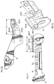
- FIG. 10 there is illustrated in schematic form the seat bracket B having the interlocking component B100 provided therewith which component includes the substantially hooked shape portion B105 and reinforcing rib B107 located proximate the rear thereof to increase the bending stiffness near the rear of the seat bracket B when subjected to a load, since this position is the portion of highest loading for the seat system.
- riser R having operating position R1, R2 and R3 the interlocking portion R100 which includes the hooked shaped portion R105 and the reinforcing portion R107 provided for the same reason as that stated in relation to B107 of Figure 10.
- the distance D2 over which the portion R100 extends cooperates with the distance D1 of Figure 10 for portion B100 so that the portions interlock over the same distance of adjustment.
- FIG. 12 there is a illustrated a closer perspective view of the portion R100 and R107 specifically of the riser portion R.
- the portion R107 as indicated in relation to the ribs B107 represents the point of highest loading for the seat system and therefore this portion R107 represents a portion of the hook portion R105 of Figure 9 which is further extended proximate the end of the seat riser R which is turned over upon itself and welded to the riser R at R108 so as to reinforce the interlocking portion R105 of the riser portion R100.
Landscapes
- Engineering & Computer Science (AREA)
- Aviation & Aerospace Engineering (AREA)
- Transportation (AREA)
- Mechanical Engineering (AREA)
- Seats For Vehicles (AREA)
- Chairs For Special Purposes, Such As Reclining Chairs (AREA)
- Vehicle Body Suspensions (AREA)
- Body Structure For Vehicles (AREA)
- Fluid-Damping Devices (AREA)
- Chairs Characterized By Structure (AREA)
- Forklifts And Lifting Vehicles (AREA)
Claims (11)
- Sitzsystem mit einem Fahrzeugrahmen oder einer Erhöhungsvorrichtung (R) zur Befestigung an einem Fahrzeugrahmen, sowie einem Sitzträger (B), der beweglich in Hinsicht auf den Rahmen oder die Erhöhungsvorrichtung befestigt ist, wobei das Sitzsystem eine Einrichtung hat, um den Sitzträger (B) aus einer und in eine vordere und hintere Position zu bewegen und zwar in Längsrichtung hinsichtlich des Rahmens oder der Erhöhungsvorrichtung (R), wobei die Bewegungseinrichtung ein Verbindungs- bzw. Stangensystem zur Zurverfügung-stellung der Längsbewegung des Sitzträgers umfaßt mit mindestens zwei Verbindungselementen bzw. Stangen (20, 30) zum Bewegen des Sitzträgers nach vorne und nach hinten und mindestens einer Kompensationseinrichtung (40) zum Kompensieren der im wesentlichen bogenförmigen Bewegung der mindestens zwei Verbindungselemente (20, 30) des Verbindungssystems des Sitzträgers, wobei die zusammenwirkende Bewegung mindestens einen Kompensationseinrichtung (40) die Bewegung des Verbindungssystems und des Sitzträgers innerhalb des Bereiches der Bewegung des Sitzträgers im wesentlichen linear macht, wobei der Rahmen oder die Erhöhungsvorrichtung (R) eine erste Sperreinrichtung (R100) hat, die mit Sperreinrichtungen des Sitzträgers über die Längsbewegung des Sitzträgers sperrt, wobei den Sitzträger eine zweite Sperreinrichtung (B100) hat, die mit der Sperreinrichtung des Rahmens oder der Erhöhungsvorrichtung über die Längsbewegung des Sitzträgers sperrt, wobei die erste und die zweite Sperreinrichtung gegenseitig benachbarte Abschnitte (R105, B105) aufweisen, welche normalerweise die Längsbewegung gestatten, aber so angeordnet sind, daß sie miteinander in Eingriff und in Kontakt kommen, wenn das System der Belastung unterzogen wird, die es während eines Unfalls erfährt, um einen direkten Weg zum Fahrzeugrahmen oder zur Erhöhungsvorrichtung für jedwede Kräfte bereitzustellen, die während des Unfalls auf das Sitzsystem ausgeübt werden, während jedwede Kräfte minimiert werden, die auf die Einrichtung zur Bewegung des Sitzträgers und von einer vorderen und einer hinteren Position hinsichtlich des Rahmens während des Unfalls ausgeübt werden.
- Sitzsystem nach Anspruch 1, dadurch gekennzeichnet, daß die mindestens zwei Verbindungselemente (20, 30) sich bei der Verwendung in einer bogenförmigen, nach oben und vorwärts gerichteten Bewegung während der Vorwärtsbewegung des Sitzträgers, und in einer bogenförmigen, nach unten und hinten gerichteten Bewegung während der Rückwärtsbewegung des Sitzträgers bewegen, und daß zur Kompensierung dieser bogenförmigen Bewegung, welche -den Kopfraum eines Sitzenden verändern würde, wenn sie unkompensiert bliebe, wenn der Sitzträger sich im Bereich seiner Längsbewegung bewegt, die Kompensationseinrichtung, die ein Verbindungselement (40) ist, sich in einer nach unten und nach vorne gerichteten bogenförmigen Kompensationsbewegung während der Vorwärtsbewegung des Sitzträgers bewegt, und in einer nach oben und nach hinten gerichteten bogenförmigen Kompensationsbewegung während der Rückwärtsbewegung des Sitzträgers, wodurch die Bewegung der mindestens zwei Verbindungselemente (20, 30) kompensiert wird und die Bewegung des Sitzträgers im Verhältnis zum stationären Rahmen oder zur Erhöhungsvorrichtung dadurch umgestaltet wird, daß der Sitzträger in einer im wesentlichen konstanten, parallelen Position hinsichtlich des Rahmens gehalten wird, und zwar über den Bewegungsbereich des Sitzträgers, so daß keine merkliche bogenförmige Bewegung stattfindet, sondern eine im wesentlichen lineare Bewegung des Sitzträgers im Verhältnis zum Rahmen.
- Sitzsystem nach Anspruch 1 oder 2, dadurch gekennzeichnet, daß die Einrichtung zur Bewegung des Sitzträgers in eine und aus einer vorderen und hinteren Position in Längsrichtung beweglich, beispielsweise schwenkbar, innerhalb der Bewegungsgrenzen des Sitzträgers zwischen einer vorbestimmten Anzahl von Stellungen ist.
- System zur Zurverfügungstellung einer linearen Bewegung eines Fahrzeugsitzes mit einem Sitzträger (B) mit einem Sitz (S), der bei der Verwendung zur Befestigung an einem Fahrzeugrahmen oder einer Erhöhungsvorrichtung (R) mit dieser vorgesehen ist, wobei der Sitzträger und die Erhöhungsvorrichtung jeweils eine Vorder- und Rückseite sowie ein Oberteil und ein Unterteil haben; wobei der Sitzträger (B) im wesentlichen bei der Verwendung am Oberteil der Erhöhungseinrichtung (R) angeordnet ist; und wobei mindestens zwei erste Verbindungselemente bzw. -stangen (30, 30a) schwenkbar mit dem Sitzträger im Eingriff sind, wobei eines der mindestens zwei ersten Verbindungselemente (30) in der Nähe des Vorderteils des Sitzträgers verbunden ist und das andere der mindestens zwei ersten Verbindungselemente (30a) in der Nähe des hinteren Teils des Sitzträgers verbunden ist; wobei mindestens zwei zweite längere Verbindungselemente bzw. -Stangen (20, 20a), die länger sind als die ersten Verbindungselemente, schwenkbar mit dem Sitzträger im Eingriff sind, wobei mindestens eines der beiden zweiten Verbindungselemente (20) schwenkbar in der Nähe der Vorderseite des Sitzträgers verbunden ist, aber nach rückwärts und in Richtung des Oberteils des Sitzträgers in Bezug auf die Anschwenkung des ersten Verbindungselements versetzt ist, und wobei das andere der mindestens zwei zweiten Verbindungselemente (20a) schwenkbar in der Nähe des hinteren Teils verbunden ist, aber in Richtung der Vorderseite und in Richtung des Oberteils des Sitzträgers versetzt, und zwar in Bezug auf die Anschwenkung des ersten Verbindungselements, wobei mindestens zwei erste (30, 30a) und zweite (20, 20a) Verbindungselemente schwenkbar mit mindestens zwei dritten Kompensations-Verbindungselementen bzw. -Stangen (40, 40a) verbunden sind, welche schwenkbar mit dem Vorderteil und dem hinteren Teil der Erhöhungseinrichtung verbunden sind, wobei mindestens zwei erste Verbindungselemente (30, 30a) mit den mindestens zwei dritten Kompensations-Verbindungselementen in der Nähe des freien Endes der mindestens zwei dritten Kompensations-Verbindungselemente (40,41) jeweils verbunden sind, wobei die mindestens zwei zweiten Verbindungselemente (20, 20a) mit den mindestens zwei dritten Kompensations-Verbindungselementen (40, 40a) zwischen den freien Enden der mindestens zwei dritten Kompensations-Verbindungselemente (40, 40a) und den Schwenkendendermindestenszwei dritten Kompensations-Verbindungselemente (40, 40a) verbunden sind, die jeweils mit der Erhöhungsvorrichtung verbunden sind, wobei die mindestens zwei ersten (30, 30a) und zweiten (20, 20a) Verbindungselemente für die längs-Vor- und -Rückbewegung des Sitzträgers in Bezug auf die Erhöhungsvorrichtung sorgen, wobei mindestens zwei dritte Kompensations-Verbindungselemente (40, 40a) die bogenförmige Bewegung der mindestens zwei ersten (30, 30a) und zweiten (20, 20a) Verbindungselemente kompensieren und den Sitzträger in einer im wesentlichen konstanten parallelen Position in Hinsicht auf die Erhöhungsvorrichtung halten, und zwar über den gesamten Bewegungsbereich des Sitzträgers, so daß keine merkliche bogenförmige Bewegung stattfindet, sondern eine im wesentlichen lineare Bewegung des Sitzträgers bezüglich der Erhöhungsvorrichtung, wobei die Erhöhungsvorrichtung eine erste Sperreinrichtung (R100) aufweist, die mit einer Sperreinrichtung des Sitzträgers über die Längsbewegung des Sitzträgers sperrt, wobei der Sitzträger eine zweite Sperreinrichtung (B100) aufweist, die mit der Sperreinrichtung der Erhöhungsvorrichtung über die Längsbewegung des Sitzträgers sperrt, wobei die erste und zweite Sperreinrichtung gegenseitig benachbarte Abschnitte (R105, B105) haben, welche normalerweise die Längsbewegung gestatten, aber so angeordnet sind, daß sie miteinander in Eingriff und Kontakt kommen, wenn das System der Belastung unterzogen wird, die es während eines Unfalls erfährt, um einen direkten Weg zum Fahrzeugrahmen für jedwede Kräfte bereitzustellen, die während eines Unfalls auf das Sitzsystem ausgeübt werden, während jedwede Kräfte, die während des Unfalls auf die ersten (30, 30a), zweiten (20, 20a) und die Kompensationsverbindungselemente (40, 40a) ausgeübt werden, minimiert werden.
- System nach Anspruch 4, dadurch gekennzeichnet, daß sich die oberen Enden der mindestens zwei ersten (30, 30a) und zweiten (20, 20a) Verbindungselemente bei der Verwendung während der Vorwärtsbewegung des Sitzes in einer gebogenen, nach oben und vorwärts gerichteten Bewegung bewegen und während der Rückwärtsbewegung des Sitzes in einer bogenförmigen nach unten und nach hinten gerichteten Bewegung; wobei zur Kompensation dieser bogenförmigen Bewegung, welche den Kopfraum eines Sitzenden verändern würde, wenn sie umkompensiert bliebe, wenn der Sitz in seinem Längsbewegungsbereich bewegt wird, die mindestens zwei dritten Kompensations-Verbindungselemente (40, 40a) sich in einer nach unten und vorwärts gerichteten bogenförmigen Kompensationsbewegung während der Vorwärtsbewegung des Sitzes bewegen, und in einer nach oben und nach hinten gerichteten bogenförmigen Kompensationsbewegung während der Rückwärtsbewegung des Sitzes, wodurch die Bewegung der mindestens zwei ersten (30, 30a) und zweiten (20, 20a) Verbindungselemente kompensiert wird und die Bewegung des Sitzträgers in Bezug auf den Rahmen durch das Halten des Sitzträgers in einer im wesentlichen konstanten parallelen Position hinsichtlich der Erhöhungsvorrichtung über dem Bewegungsbereich des Sitzträgers -umgewandelt wird, so daß keine merkliche bogenförmige Bewegung stattfindet, sondern eine im wesentlichen lineare Bewegung des Sitzträgers in Bezug auf die Erhöhungsvorrichtung.
- System nach Anspruch 4 oder 5, dadurch gekennzeichnet, daß die Erhöhungsvorrichtung ferner integrale Arretierungsabschnitte (R1, R2, R3) aufweist, die in der Nähe ihres Oberteils angeordnet sind, um den Sitzträger in Bezug auf die Erhöhungsvorrichtung bei verschiedenen Arretierungspositionen in Relation hierzu zu befestigen, wobei der Sitzträger eine Rasteinrichtung (50) umfaßt, welche die Rastabschnitte der Erhöhungsvorrichtung lösbar in Eingriff nimmt, wenn der Sitz in und aus alternativen Komfortpositionen bewegt wird.
- System nach Anspruch 6, dadurch gekennzeichnet, daß der Sitzträger und/oder die Erhöhungsvorrichtung ferner Abschnitte umfaßt, die in der Nähe des Unterteils des Sitzträgers oder des Oberteils der Erhöhungsvorrichtung angeordnet sind, und welche einander in Eingriff nehmen und einen Widerstand gegenüber seitlichen Kräften bieten, die dazu neigen, den Träger seitlich in Bezug auf die Erhöhungsvorrichtung zu bewegen, und die dabei helfen, den Träger in Bezug auf die Erhöhungsvorrichtung in Längsrichtung zu führen.
- System nach Anspruch 7, dadurch gekennzeichnet, daß die Abschnitte sich nach unten erstreckende Flansche (B100) des Sitzträgers sind, welche das Oberteil der Erhöhungsvorrichtung (R105) umgeben und ferner dabei helfen, die Längsbewegung des Sitzträgers in Bezug auf die Erhöhungsvorrichtung zu führen.
- System nach Anspruch 8, dadurch gekennzeichnet, daß die Rasteinrichtungen, wenn sie gleichzeitig verrastet werden, sich durch Öffnungen in der Erhöhungsvorrichtung und durch ausgerichtete Öffnungen erstrecken, welche sich durch den Sitzträger erstrecken.
- System nach einem der Ansprüche 4 bis 9, dadurch gekennzeichnet, daß die Erhöhungsvorrichtung ferner einer integralen Rastabschnitt (P1, P2, P3, P4) in der Nähe ihres Unterteils zur Befestigung der Erhöhungseinrichtung, des Sitzträgers und des Sitzes an Bodenrastabschnitten bei der Verwendung aufweist.
- System nach einem der vorhergehenden Ansprüche, bei dem die ersten und zweiten Sperreinrichtungen relativ zueinander versetzbar sind, bis eine Belastung auf das System ausgeübt wird.
Applications Claiming Priority (4)
| Application Number | Priority Date | Filing Date | Title |
|---|---|---|---|
| CA002072809A CA2072809C (en) | 1992-06-30 | 1992-06-30 | Seat adjuster with compensating link |
| CA2072809 | 1992-06-30 | ||
| PCT/CA1993/000058 WO1994000313A1 (en) | 1992-06-30 | 1993-02-12 | Interlocking seat adjuster with compensating link |
| US08/354,881 US5472165A (en) | 1992-06-30 | 1994-12-09 | Seat adjuster with compensating link |
Publications (2)
| Publication Number | Publication Date |
|---|---|
| EP0601136A1 EP0601136A1 (de) | 1994-06-15 |
| EP0601136B1 true EP0601136B1 (de) | 1999-01-20 |
Family
ID=25675286
Family Applications (1)
| Application Number | Title | Priority Date | Filing Date |
|---|---|---|---|
| EP93903751A Expired - Lifetime EP0601136B1 (de) | 1992-06-30 | 1993-02-12 | Ineinandergreifende sitzverstellvorrichtung mit kompensationsstange |
Country Status (9)
| Country | Link |
|---|---|
| US (1) | US5472165A (de) |
| EP (1) | EP0601136B1 (de) |
| JP (1) | JP2609575B2 (de) |
| AT (1) | ATE175928T1 (de) |
| AU (1) | AU3488593A (de) |
| CA (2) | CA2072809C (de) |
| DE (1) | DE69323164T2 (de) |
| ES (1) | ES2127268T3 (de) |
| WO (1) | WO1994000313A1 (de) |
Families Citing this family (19)
| Publication number | Priority date | Publication date | Assignee | Title |
|---|---|---|---|---|
| US6199252B1 (en) | 1995-11-27 | 2001-03-13 | Lear Corporation | Modular seat assembly and method of installing the same within a vehicle |
| US6010195A (en) * | 1995-11-27 | 2000-01-04 | Lear Corporation | Automotive modular seat frame assembly |
| US5967471A (en) * | 1997-12-17 | 1999-10-19 | Lear Corporation | Vehicle parallel seat lift with stable linkage |
| FR2772686B3 (fr) * | 1997-12-22 | 2000-02-18 | Faure Bertrand Equipements Sa | Ensemble d'assise pour vehicule comportant un siege amovible monte sur glissieres |
| US6089665A (en) * | 1998-07-02 | 2000-07-18 | Dura Automotive Properties Inc. | Load transfer structural member for a seat assembly |
| US6354556B1 (en) | 1999-02-04 | 2002-03-12 | Freightliner Llc | Seat suspension method |
| US6371456B1 (en) | 1999-02-04 | 2002-04-16 | Freightliner Llc | Seat suspension system |
| US6241209B1 (en) | 1999-02-04 | 2001-06-05 | Freightliner Llc | Seat support |
| US6340152B1 (en) | 1999-02-04 | 2002-01-22 | Freightliner Llc | Seat suspension vibration damper |
| US6286819B1 (en) | 1999-02-04 | 2001-09-11 | Freightliner Corporation Llc | Vibration damper with latch |
| US6145929A (en) * | 1999-03-29 | 2000-11-14 | Gollahon; Robert | Sliding insert for a fishing chair |
| US6405987B1 (en) | 1999-08-05 | 2002-06-18 | Dura Global Technologies, Inc. | Reinforcement member for a seat mounting assembly |
| US6817673B2 (en) | 2002-04-17 | 2004-11-16 | Lear Corporation | Vehicle seat assembly |
| US7140589B2 (en) * | 2003-12-10 | 2006-11-28 | Orchid Automation, Llc | Cushion lift for seat assembly |
| US7581792B2 (en) * | 2005-06-07 | 2009-09-01 | Lear Corporation | Vehicle seat frame structure and method of assembling a portion of a vehicle seat frame |
| US7866689B2 (en) * | 2005-08-19 | 2011-01-11 | Lear Corporation | Vehicle seat frame structure and method of manufacturing same |
| DE102008017710A1 (de) * | 2008-04-08 | 2009-10-15 | GM Global Technology Operations, Inc., Detroit | Sitzanordnung für ein Kraftfahrzeug mit einem längsverschiebbaren mittleren Fahrzeugsitz |
| US9242586B2 (en) * | 2014-04-11 | 2016-01-26 | Brose Fahrzeugteile Gmbh & Co. Kommanditgesellschaft, Coburg | Seat riser |
| CN115916585A (zh) * | 2020-06-25 | 2023-04-04 | 麦格纳座椅公司 | 具有超控状态的座椅组件 |
Family Cites Families (28)
| Publication number | Priority date | Publication date | Assignee | Title |
|---|---|---|---|---|
| US2921621A (en) * | 1952-08-01 | 1960-01-19 | American Metal Prod | Vertically and horizontally adjusted seat frame |
| US2920684A (en) * | 1955-05-25 | 1960-01-12 | Rockwell Standard Co | Seat support |
| US2942647A (en) * | 1957-08-26 | 1960-06-28 | Ferro Stamping Co | Slideless seat support and adjusting device |
| US2902211A (en) * | 1958-09-05 | 1959-09-01 | William E Franklin | Mailbox |
| US3037735A (en) * | 1958-10-13 | 1962-06-05 | Gen Motors Corp | Trackless six-way seat adjuster |
| US3006594A (en) * | 1958-11-12 | 1961-10-31 | Gen Motors Corp | Linkage seat adjuster with straight line movement |
| US2980163A (en) * | 1958-12-15 | 1961-04-18 | Ferro Stamping Co | Adjustable seat support mechanism |
| US3008681A (en) * | 1959-08-20 | 1961-11-14 | Gen Motors Corp | Vehicle seat adjuster |
| US3022035A (en) * | 1959-11-02 | 1962-02-20 | Ferro Stamping Co | Seat supporting and adjusting mechanism |
| US3137472A (en) * | 1962-02-27 | 1964-06-16 | Gen Motors Corp | Vehicle seat adjuster |
| US3136524A (en) * | 1962-06-18 | 1964-06-09 | Ferro Stamping Co | Vehicle seat track |
| US3149815A (en) * | 1963-03-25 | 1964-09-22 | Gen Motors Corp | Manual seat adjuster |
| GB1082004A (en) * | 1965-04-27 | 1967-09-06 | Hallam Sleigh & Cheston Ltd | Improvements in adjustable seats |
| US4010927A (en) * | 1975-12-03 | 1977-03-08 | Ferro Manufacturing Corporation | Seat adjusting mechanism |
| DE2626441A1 (de) * | 1976-06-12 | 1977-12-22 | Keiper Automobiltechnik Gmbh | Hoehenverstellbarer sitz insbesondere fahrzeugsitz |
| DE2855293A1 (de) * | 1978-12-21 | 1980-07-03 | Fichtel & Sachs Ag | Mehrgelenkgetriebe |
| GB2187379B (en) * | 1986-03-05 | 1990-04-04 | Ti Cox Ltd | Height adjustment mechanism |
| FI882921L (fi) * | 1986-10-20 | 1988-06-17 | Novo Industri As | Protaminzink-insulinpreparat. |
| DE3643729C2 (de) * | 1986-12-20 | 1995-08-24 | Audi Ag | Sitzhalterung mit Sitzverstellung für einen Fahrzeugsitz |
| DE3715258C2 (de) * | 1987-05-08 | 1996-10-31 | Haselmeier Wilhelm Fa | Injektionsgerät |
| US4807932A (en) * | 1987-08-13 | 1989-02-28 | Kia Motors Corporation | Device for moving an automobile seat back and forth |
| US4941879A (en) * | 1987-10-14 | 1990-07-17 | John H. A. Butler | Single use syringe |
| CH675078A5 (de) * | 1988-01-22 | 1990-08-31 | Nosta Ag | |
| AU626902B2 (en) * | 1989-08-03 | 1992-08-13 | Tachi-S Co., Ltd. | Height adjusting device for automotive seat |
| WO1991004881A1 (en) * | 1989-10-05 | 1991-04-18 | Vipac Engineers & Scientists Ltd. | A seat suspension |
| DE4010451C2 (de) * | 1990-03-31 | 1998-07-23 | Audi Ag | Sitz für Kraftfahrzeuge |
| JP2910179B2 (ja) * | 1990-07-26 | 1999-06-23 | アイシン精機株式会社 | 車両用シートの上下位置調整装置 |
| US5154402A (en) * | 1991-05-10 | 1992-10-13 | Milsco Manufacturing Company | Vehicle seat suspension |
-
1992
- 1992-06-30 CA CA002072809A patent/CA2072809C/en not_active Expired - Lifetime
-
1993
- 1993-02-12 CA CA002116573A patent/CA2116573C/en not_active Expired - Lifetime
- 1993-02-12 EP EP93903751A patent/EP0601136B1/de not_active Expired - Lifetime
- 1993-02-12 ES ES93903751T patent/ES2127268T3/es not_active Expired - Lifetime
- 1993-02-12 AT AT93903751T patent/ATE175928T1/de active
- 1993-02-12 DE DE69323164T patent/DE69323164T2/de not_active Expired - Lifetime
- 1993-02-12 AU AU34885/93A patent/AU3488593A/en not_active Abandoned
- 1993-02-12 WO PCT/CA1993/000058 patent/WO1994000313A1/en not_active Ceased
- 1993-02-12 JP JP6501902A patent/JP2609575B2/ja not_active Expired - Lifetime
-
1994
- 1994-12-09 US US08/354,881 patent/US5472165A/en not_active Expired - Lifetime
Also Published As
| Publication number | Publication date |
|---|---|
| CA2072809A1 (en) | 1993-12-31 |
| AU3488593A (en) | 1994-01-24 |
| ES2127268T3 (es) | 1999-04-16 |
| DE69323164T2 (de) | 1999-06-02 |
| ATE175928T1 (de) | 1999-02-15 |
| DE69323164D1 (de) | 1999-03-04 |
| US5472165A (en) | 1995-12-05 |
| CA2116573C (en) | 1998-12-15 |
| JPH07500793A (ja) | 1995-01-26 |
| JP2609575B2 (ja) | 1997-05-14 |
| EP0601136A1 (de) | 1994-06-15 |
| CA2072809C (en) | 1998-05-19 |
| WO1994000313A1 (en) | 1994-01-06 |
| CA2116573A1 (en) | 1994-01-06 |
Similar Documents
| Publication | Publication Date | Title |
|---|---|---|
| EP0601136B1 (de) | Ineinandergreifende sitzverstellvorrichtung mit kompensationsstange | |
| EP2065251B1 (de) | Fahrzeugsitz | |
| US5306073A (en) | High strength motor vehicle seat recliner | |
| US6517157B1 (en) | Apparatus for adjusting a seat belt | |
| JP5477537B2 (ja) | 車両のシートベルト装置 | |
| US9855868B2 (en) | Seat adjuster assembly | |
| US5338100A (en) | High strength automotive seat frame and method | |
| US5288134A (en) | Seat assembly with integrated seat cushion and seat track frame | |
| EP0881970A2 (de) | Automatischer höhen- und neigungsverstellmechanismus einer rückenlehne | |
| US5755422A (en) | Automotive seat track assembly having safety locking device | |
| JPH04252744A (ja) | パワーシートスライド装置 | |
| EP0289468B1 (de) | Vordersitz für Kraftfahrzeuge mit zwei Türen | |
| US7246845B2 (en) | Structural seat system for an automotive vehicle | |
| US5664755A (en) | Interlocking seat adjuster with compensating link | |
| US10131251B2 (en) | Seat adjuster assembly | |
| US20050161980A1 (en) | Structural seat system for an automotive vehicle | |
| EP3765331B1 (de) | Sekundärer stabilisierungsschlagbolzen für umklappbare sitze | |
| US7481486B2 (en) | Structural seat system for an automotive vehicle | |
| EP0863820B1 (de) | Hebelmechanismus für motorisch-verstellbarem Fahrzeugsitz mit Drehblockierung | |
| US5570508A (en) | Method of making a high strength automotive seat frame | |
| EP1186469A1 (de) | Eine Rückenlehne für einen Kraftfahrzeugsitz, insbesondere für einen Rücksitz | |
| CN117141322A (zh) | 交通工具用座椅 | |
| JP3104737B2 (ja) | シートスライド装置のロック機構 | |
| JP3399634B2 (ja) | シートレール装置 | |
| JPH0428262Y2 (de) |
Legal Events
| Date | Code | Title | Description |
|---|---|---|---|
| PUAI | Public reference made under article 153(3) epc to a published international application that has entered the european phase |
Free format text: ORIGINAL CODE: 0009012 |
|
| 17P | Request for examination filed |
Effective date: 19940311 |
|
| AK | Designated contracting states |
Kind code of ref document: A1 Designated state(s): AT BE CH DE DK ES FR GB GR IE IT LI LU MC NL PT SE |
|
| 17Q | First examination report despatched |
Effective date: 19950606 |
|
| GRAG | Despatch of communication of intention to grant |
Free format text: ORIGINAL CODE: EPIDOS AGRA |
|
| GRAG | Despatch of communication of intention to grant |
Free format text: ORIGINAL CODE: EPIDOS AGRA |
|
| GRAH | Despatch of communication of intention to grant a patent |
Free format text: ORIGINAL CODE: EPIDOS IGRA |
|
| RAP1 | Party data changed (applicant data changed or rights of an application transferred) |
Owner name: MULTIMATIC INC. |
|
| GRAH | Despatch of communication of intention to grant a patent |
Free format text: ORIGINAL CODE: EPIDOS IGRA |
|
| GRAA | (expected) grant |
Free format text: ORIGINAL CODE: 0009210 |
|
| AK | Designated contracting states |
Kind code of ref document: B1 Designated state(s): AT BE CH DE DK ES FR GB GR IE IT LI LU MC NL PT SE |
|
| PG25 | Lapsed in a contracting state [announced via postgrant information from national office to epo] |
Ref country code: NL Free format text: LAPSE BECAUSE OF FAILURE TO SUBMIT A TRANSLATION OF THE DESCRIPTION OR TO PAY THE FEE WITHIN THE PRESCRIBED TIME-LIMIT Effective date: 19990120 Ref country code: LI Free format text: LAPSE BECAUSE OF FAILURE TO SUBMIT A TRANSLATION OF THE DESCRIPTION OR TO PAY THE FEE WITHIN THE PRESCRIBED TIME-LIMIT Effective date: 19990120 Ref country code: GR Free format text: LAPSE BECAUSE OF NON-PAYMENT OF DUE FEES Effective date: 19990120 Ref country code: CH Free format text: LAPSE BECAUSE OF FAILURE TO SUBMIT A TRANSLATION OF THE DESCRIPTION OR TO PAY THE FEE WITHIN THE PRESCRIBED TIME-LIMIT Effective date: 19990120 Ref country code: BE Free format text: LAPSE BECAUSE OF FAILURE TO SUBMIT A TRANSLATION OF THE DESCRIPTION OR TO PAY THE FEE WITHIN THE PRESCRIBED TIME-LIMIT Effective date: 19990120 |
|
| REF | Corresponds to: |
Ref document number: 175928 Country of ref document: AT Date of ref document: 19990215 Kind code of ref document: T |
|
| ITF | It: translation for a ep patent filed | ||
| REG | Reference to a national code |
Ref country code: CH Ref legal event code: EP |
|
| PG25 | Lapsed in a contracting state [announced via postgrant information from national office to epo] |
Ref country code: LU Free format text: LAPSE BECAUSE OF NON-PAYMENT OF DUE FEES Effective date: 19990212 |
|
| REG | Reference to a national code |
Ref country code: IE Ref legal event code: FG4D |
|
| REF | Corresponds to: |
Ref document number: 69323164 Country of ref document: DE Date of ref document: 19990304 |
|
| PG25 | Lapsed in a contracting state [announced via postgrant information from national office to epo] |
Ref country code: IE Free format text: LAPSE BECAUSE OF NON-PAYMENT OF DUE FEES Effective date: 19990320 |
|
| ET | Fr: translation filed | ||
| REG | Reference to a national code |
Ref country code: ES Ref legal event code: FG2A Ref document number: 2127268 Country of ref document: ES Kind code of ref document: T3 |
|
| PG25 | Lapsed in a contracting state [announced via postgrant information from national office to epo] |
Ref country code: PT Free format text: LAPSE BECAUSE OF FAILURE TO SUBMIT A TRANSLATION OF THE DESCRIPTION OR TO PAY THE FEE WITHIN THE PRESCRIBED TIME-LIMIT Effective date: 19990420 Ref country code: DK Free format text: LAPSE BECAUSE OF FAILURE TO SUBMIT A TRANSLATION OF THE DESCRIPTION OR TO PAY THE FEE WITHIN THE PRESCRIBED TIME-LIMIT Effective date: 19990420 |
|
| PG25 | Lapsed in a contracting state [announced via postgrant information from national office to epo] |
Ref country code: DE Free format text: LAPSE BECAUSE OF FAILURE TO SUBMIT A TRANSLATION OF THE DESCRIPTION OR TO PAY THE FEE WITHIN THE PRESCRIBED TIME-LIMIT Effective date: 19990421 |
|
| NLV1 | Nl: lapsed or annulled due to failure to fulfill the requirements of art. 29p and 29m of the patents act | ||
| REG | Reference to a national code |
Ref country code: CH Ref legal event code: PL |
|
| PG25 | Lapsed in a contracting state [announced via postgrant information from national office to epo] |
Ref country code: MC Free format text: LAPSE BECAUSE OF NON-PAYMENT OF DUE FEES Effective date: 19990831 |
|
| PLBE | No opposition filed within time limit |
Free format text: ORIGINAL CODE: 0009261 |
|
| 26N | No opposition filed | ||
| REG | Reference to a national code |
Ref country code: IE Ref legal event code: MM4A |
|
| REG | Reference to a national code |
Ref country code: GB Ref legal event code: IF02 |
|
| PGFP | Annual fee paid to national office [announced via postgrant information from national office to epo] |
Ref country code: FR Payment date: 20120221 Year of fee payment: 20 |
|
| PGFP | Annual fee paid to national office [announced via postgrant information from national office to epo] |
Ref country code: DE Payment date: 20120208 Year of fee payment: 20 |
|
| PGFP | Annual fee paid to national office [announced via postgrant information from national office to epo] |
Ref country code: SE Payment date: 20120215 Year of fee payment: 20 Ref country code: IT Payment date: 20120223 Year of fee payment: 20 Ref country code: GB Payment date: 20120208 Year of fee payment: 20 |
|
| REG | Reference to a national code |
Ref country code: DE Ref legal event code: R071 Ref document number: 69323164 Country of ref document: DE |
|
| REG | Reference to a national code |
Ref country code: DE Ref legal event code: R071 Ref document number: 69323164 Country of ref document: DE |
|
| REG | Reference to a national code |
Ref country code: GB Ref legal event code: PE20 Expiry date: 20130211 |
|
| REG | Reference to a national code |
Ref country code: AT Ref legal event code: MK07 Ref document number: 175928 Country of ref document: AT Kind code of ref document: T Effective date: 20130212 |
|
| PGFP | Annual fee paid to national office [announced via postgrant information from national office to epo] |
Ref country code: AT Payment date: 20120126 Year of fee payment: 20 |
|
| REG | Reference to a national code |
Ref country code: SE Ref legal event code: EUG |
|
| PG25 | Lapsed in a contracting state [announced via postgrant information from national office to epo] |
Ref country code: DE Free format text: LAPSE BECAUSE OF EXPIRATION OF PROTECTION Effective date: 20130213 Ref country code: GB Free format text: LAPSE BECAUSE OF EXPIRATION OF PROTECTION Effective date: 20130211 |
|
| PGFP | Annual fee paid to national office [announced via postgrant information from national office to epo] |
Ref country code: ES Payment date: 20120307 Year of fee payment: 20 |
|
| REG | Reference to a national code |
Ref country code: ES Ref legal event code: FD2A Effective date: 20140827 |
|
| PG25 | Lapsed in a contracting state [announced via postgrant information from national office to epo] |
Ref country code: ES Free format text: LAPSE BECAUSE OF EXPIRATION OF PROTECTION Effective date: 20130213 |