EP0600574A2 - Wärmetauscher - Google Patents
Wärmetauscher Download PDFInfo
- Publication number
- EP0600574A2 EP0600574A2 EP93305445A EP93305445A EP0600574A2 EP 0600574 A2 EP0600574 A2 EP 0600574A2 EP 93305445 A EP93305445 A EP 93305445A EP 93305445 A EP93305445 A EP 93305445A EP 0600574 A2 EP0600574 A2 EP 0600574A2
- Authority
- EP
- European Patent Office
- Prior art keywords
- base
- stack
- passage
- housing
- heat exchanger
- Prior art date
- Legal status (The legal status is an assumption and is not a legal conclusion. Google has not performed a legal analysis and makes no representation as to the accuracy of the status listed.)
- Granted
Links
Images
Classifications
-
- F—MECHANICAL ENGINEERING; LIGHTING; HEATING; WEAPONS; BLASTING
- F28—HEAT EXCHANGE IN GENERAL
- F28D—HEAT-EXCHANGE APPARATUS, NOT PROVIDED FOR IN ANOTHER SUBCLASS, IN WHICH THE HEAT-EXCHANGE MEDIA DO NOT COME INTO DIRECT CONTACT
- F28D9/00—Heat-exchange apparatus having stationary plate-like or laminated conduit assemblies for both heat-exchange media, the media being in contact with different sides of a conduit wall
- F28D9/0012—Heat-exchange apparatus having stationary plate-like or laminated conduit assemblies for both heat-exchange media, the media being in contact with different sides of a conduit wall the apparatus having an annular form
-
- F—MECHANICAL ENGINEERING; LIGHTING; HEATING; WEAPONS; BLASTING
- F28—HEAT EXCHANGE IN GENERAL
- F28D—HEAT-EXCHANGE APPARATUS, NOT PROVIDED FOR IN ANOTHER SUBCLASS, IN WHICH THE HEAT-EXCHANGE MEDIA DO NOT COME INTO DIRECT CONTACT
- F28D21/00—Heat-exchange apparatus not covered by any of the groups F28D1/00 - F28D20/00
- F28D2021/0019—Other heat exchangers for particular applications; Heat exchange systems not otherwise provided for
- F28D2021/008—Other heat exchangers for particular applications; Heat exchange systems not otherwise provided for for vehicles
- F28D2021/0089—Oil coolers
-
- Y—GENERAL TAGGING OF NEW TECHNOLOGICAL DEVELOPMENTS; GENERAL TAGGING OF CROSS-SECTIONAL TECHNOLOGIES SPANNING OVER SEVERAL SECTIONS OF THE IPC; TECHNICAL SUBJECTS COVERED BY FORMER USPC CROSS-REFERENCE ART COLLECTIONS [XRACs] AND DIGESTS
- Y10—TECHNICAL SUBJECTS COVERED BY FORMER USPC
- Y10S—TECHNICAL SUBJECTS COVERED BY FORMER USPC CROSS-REFERENCE ART COLLECTIONS [XRACs] AND DIGESTS
- Y10S165/00—Heat exchange
- Y10S165/916—Oil cooler
Definitions
- This invention relates to heat exchangers, and more particularly, to heat exchangers employed as oil coolers for cooling the oil of internal combustion engines.
- a stack of individual heat exchange units is located within the donut oil cooler.
- Engine oil passes through the donut oil cooler to the filter and then is returned through the donut oil cooler to the engine, directly through the engine block.
- the oil is passed through the stack of individual heat exchange units.
- Engine coolant is flowed about the exterior of the stack to achieve heat rejection from the oil to the engine coolant.
- donut oil coolers Because of the simplicity, compactness and ease of installation, donut oil coolers have achieved a great deal of popularity and the end of their usefulness is not in sight.
- the present invention is directed to an improvement in a donut oil cooler, and more particularly, to the elimination of the need for external coolant lines to be connected between the donut oil cooler and engine cooling system.
- An exemplary embodiment of the invention achieves the foregoing in an oil cooler adapted to be mounted on the block of an internal combustion engine.
- the oil cooler includes a housing having a base. Spaced coolant ports are located in the base.
- a filter mounting surface is located on the housing and oppositely of the base and a heat exchange stack is disposed within the housing. The stack has an oil inlet or outlet port in the base and an oil outlet or inlet port in the filter mounting surface.
- a passage extends through the housing from the base to the filter mounting surface.
- oil to be cooled may be admitted to the heat exchange stack through ports in the base as is conventional while coolant may be introduced into the housing from a port in the base and returned to the engine block through another port in the base, thereby eliminating the need for external hose connections into the vehicle cooling system.
- the stack is located between the coolant ports.
- the base and the housing have parallelogram shapes and the filter mounting surface is an annular surface.
- the coolant ports are in opposite corners of the parallelogram shape of the base.
- a highly preferred embodiment contemplates that the stack be made up of a plurality of interconnected, but spaced, heat exchange units.
- a heat exchanger that includes a stack of heat exchange units. Each unit includes a pair of spaced plates joined at their peripheral edges with the unit in the stack being spaced from one another. Means are provided to define a first passage through the stack such that the first passage is sealed from the heat exchange units. Means are provided to define a second passage in fluid communication with the interiors of the heat exchange units. The second passage has an opening to one end of the stack.
- Means are also provided to define a third passage in fluid communication with the interiors of the heat exchange units.
- the third passage is in spaced relation to the second passage and has an opening to the opposite end of the stack.
- a housing contains the stack and the housing includes a base adapted to be abutted to a source of two heat exchange fluids and an opposite side.
- a pair of first ports are provided. One of the first ports is located in the base and the other is in the opposite side of the housing and the two define opposite ends of the first passage.
- a second port is located in the base and in fluid communication with the opening for the second passage.
- a third port is disposed in the opposite side of the housing and is in fluid communication with the third passage opening.
- Fourth and fifth ports are disposed in the base and spaced from one another on generally opposite sides of the stack.
- the base is provided with seal means for sealing against the element to which the heat exchanger may be mounted.
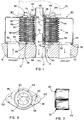
- FIG. 1 An exemplary embodiment of a heat exchanger made according to the invention is illustrated in Fig. 1 as an oil cooler for the engine oil of an internal combustion engine, as this is apt to be the most likely use for the heat exchanger. However, it is to be understood that the heat exchanger is subject to use in exchanging heat between fluids other than engine oil and engine coolant.
- an internal combustion engine block is schematically illustrated and generally designated 10.
- the same includes an engine oil outlet 12 which is intended to direct engine oil to a conventional oil filter.
- An oil return passage 14 is also provided in the block and terminates in a threaded nipple 16 upon which an oil filter would be mounted in a convention fashion.
- the block 10 On one side of the oil passage 12, the block 10 includes a coolant outlet 18 while on the opposite side of the passages 12 and 14, a coolant inlet 20 is provided.
- an adapter/extender 22 Mounted on the block 10 by means of an adapter/extender 22 is a heat exchanger made according to the invention.
- the adapter/extender 22 may be of the form disclosed in commonly assigned United States Letters Patent 4,360,055 issued November 23, 1982 to Donald J. Frost, the details of which are herein incorporated by reference. It is sufficient to say that the adapter/extender 22 includes an internally threaded bore 24 that is threaded on the nipple 16. Oppositely thereof, the adapter/extender 22 includes hexagonal head 26 and a threaded nipple 28. As schematically illustrated in dotted lines in Fig. 1, a conventional oil filter 30 may be spin mounted on the nipple 28.
- the basic components of the heat exchanger are a housing, generally designated 32, and a heat exchange stack, generally designated 34, contained within the housing 32.
- the stack 34 may be made-up of a plurality of interconnected, but spaced heat exchange units 36.
- the heat exchange units 36 are in turn made up of a pair of spaced plates 38 and 40 that are sealed about their peripheries 42 as, for example, by clinching.
- Spacers 44 of conventional construction may be disposed between individual ones of the units 36 to achieve the desired spacing while the interior of the units 36 may be partially occupied by strand-like turbulators 46 as is well known.
- the stack 34 occupies a generally cylindrical envelope. At its center, each of the units 36 in the stack 34 has a central opening 50 which defines a first passage that extends entirely through the stack 34. Parts of the spacers 44 isolate the passage defined by the opening 50 from the interiors of the individual units 36. The size of the passage defined by the openings 50 is such as to receive the nipple 16 on the block 10 as well as the adapter/extender 22.
- the passage also terminates at one end in a port 62 in a base 64 of the housing 32. At its opposite end, the port or passage defined by the openings 50 terminates in a port 66 in a filter mounting surface 68 on the side of the housing 32 opposite the base 64.
- the hex head 26 on the adapter/extender 22 overlies the surface 68 and when the adapter/extender 22 is threaded in place, the hex head 26 serves to clamp the heat exchanger in place on the engine block 10.
- a combination of openings in the spacers 44 and in the plates 38 and 40 define a second passage 70 that is in fluid communication with the interior of the heat exchange units 36.
- the second passage 70 terminates at one end of the stack in a port 72 in the base 64.
- a third passage 74 is defined by openings in the plates 38 and 40 as well as the spacers 44 and is in fluid communication with the interior of the heat exchange units 36 on the side of the central opening 50 opposite from the second passage 70.
- the passage 74 opens in a port 76 in the surface 68.
- the surface 68 of the housing 32 is surrounded by an annular ring-like structure 80 that is typically brazed to the housing 32 and which has an annular, generally planer, sealing surface 82 against which the conventional seal 84 of the filter 30 may sealingly engage.
- the base 64 is provided with an annulus seal receiving groove 86 containing a seal 88.
- the groove 86 is centered on the central opening 50 and disposed to encompass the interface of the base 64 and the oil passages 12 and 14.
- the oil passage 12 in the block 10 may include a partial or complete annulate 90 that will align with the port 72 when the housing 32 is installed so that engine oil may be introduced into the heat exchanger via the second passage 70.
- the base 64 includes, near its periphery, one or more grooves 92 for a corresponding number of O-ring seals 94.
- the seals 94 are located outwardly of coolant passages 18 and 20 and with the seal 88 serve to confine coolant to a certain part of the interface of the base 64 with the block 10.
- the base 64 includes a port 96 on one side of the stack 34 which aligns with the coolant outlet port 18 to receive and direct coolant to the interior of the housing 32.
- a coolant outlet port 98 for the heat exchanger is located in the base 64 on the opposite side of the stack 34 and serves to direct coolant from the heat exchanger to the coolant inlet 20.
- the housing 32 and the base 64 thereof are configured as a parallelogram, and even more specifically, as a slightly rounded diamond shape as seen in Fig. 2.
- the diamond shape has opposite points 100 and 102 in which the ports 96 and 98 are respectively located.
- ports 96 and 98 are on opposite sides of the stack 34, assuring uniform flow of coolant between the individual heat exchange units to maximize efficiency.
- Oil flow is as conventional in donut oil coolers. As noted previously, oil to be cooled is introduced into the second passage 70. This will place oil within the interior of the individual units 36 and the same will flow about the central opening 50 in each to the third passage 74. The oil will be collected at the third passage 74 and directed via the port 76 to the inlet of the oil filter 30. After being filtered, the oil will be returned to the oil port 14 in the engine block via the adapter/extender 22.
- a heat exchanger made according to the invention is ideally suited for use in many applications, particularly as an oil cooler for the engine oil of an internal combustion engine.
- a heat exchanger made according to the invention is ideally suited for use in many applications, particularly as an oil cooler for the engine oil of an internal combustion engine.
Landscapes
- Engineering & Computer Science (AREA)
- Physics & Mathematics (AREA)
- Thermal Sciences (AREA)
- Mechanical Engineering (AREA)
- General Engineering & Computer Science (AREA)
- Heat-Exchange Devices With Radiators And Conduit Assemblies (AREA)
- Lubrication Of Internal Combustion Engines (AREA)
- Lubrication Details And Ventilation Of Internal Combustion Engines (AREA)
Applications Claiming Priority (2)
| Application Number | Priority Date | Filing Date | Title |
|---|---|---|---|
| US07/983,731 US5558154A (en) | 1992-12-01 | 1992-12-01 | Captive flow donut oil cooler |
| US983731 | 1992-12-01 |
Publications (3)
| Publication Number | Publication Date |
|---|---|
| EP0600574A2 true EP0600574A2 (de) | 1994-06-08 |
| EP0600574A3 EP0600574A3 (en) | 1994-09-07 |
| EP0600574B1 EP0600574B1 (de) | 1997-06-25 |
Family
ID=25530074
Family Applications (1)
| Application Number | Title | Priority Date | Filing Date |
|---|---|---|---|
| EP93305445A Expired - Lifetime EP0600574B1 (de) | 1992-12-01 | 1993-07-12 | Wärmetauscher |
Country Status (10)
| Country | Link |
|---|---|
| US (1) | US5558154A (de) |
| EP (1) | EP0600574B1 (de) |
| JP (1) | JPH06213581A (de) |
| KR (1) | KR100308892B1 (de) |
| AU (1) | AU671126B2 (de) |
| BR (1) | BR9304135A (de) |
| CA (1) | CA2100736A1 (de) |
| DE (1) | DE69311789T2 (de) |
| MX (1) | MX9306292A (de) |
| TW (1) | TW237426B (de) |
Cited By (2)
| Publication number | Priority date | Publication date | Assignee | Title |
|---|---|---|---|---|
| DE19716200A1 (de) * | 1997-04-18 | 1998-10-22 | Funke Waerme Apparate Kg | Plattenwärmeaustauscher |
| EP1124105A3 (de) * | 2000-02-10 | 2002-12-04 | Filterwerk Mann + Hummel Gmbh | Flüssigkeitskühlersystem |
Families Citing this family (11)
| Publication number | Priority date | Publication date | Assignee | Title |
|---|---|---|---|---|
| DE29716257U1 (de) * | 1997-09-10 | 1997-11-06 | Behr Gmbh & Co | Stapelscheiben-Wärmeübertrager |
| US6935417B1 (en) * | 1998-10-19 | 2005-08-30 | Ebara Corporation | Solution heat exchanger for absorption refrigerating machine |
| JP2001082590A (ja) * | 1999-09-10 | 2001-03-27 | Honda Motor Co Ltd | 油圧作動式変速機における油温調整装置 |
| JP4077610B2 (ja) * | 2001-03-16 | 2008-04-16 | カルソニックカンセイ株式会社 | ハウジングレス式オイルクーラ |
| US20040173341A1 (en) * | 2002-04-25 | 2004-09-09 | George Moser | Oil cooler and production method |
| DE10347181B4 (de) * | 2003-10-10 | 2005-12-22 | Modine Manufacturing Co., Racine | Wärmetauscher, insbesondere Ölkühler |
| DE102005012550A1 (de) | 2005-03-18 | 2006-09-21 | Mahle International Gmbh | Filter-Kühler-Kombination für Flüssigkeiten, insbesondere Schmieröl eines Kraftfahrzeug-Verbrennungsmotors |
| DE102009050016A1 (de) * | 2009-05-27 | 2011-05-05 | Modine Manufacturing Co., Racine | Wärmeübertragereinheit |
| US10113803B2 (en) * | 2014-11-13 | 2018-10-30 | Hamilton Sundstrand Corporation | Round heat exchanger |
| WO2019084379A1 (en) * | 2017-10-26 | 2019-05-02 | Cummins Inc. | COOLED LUBRICANT FILTER HOUSING |
| EP4146920A4 (de) * | 2020-05-08 | 2024-04-24 | Cummins Inc | Schmiermittelverteiler für verbrennungsmotor |
Citations (3)
| Publication number | Priority date | Publication date | Assignee | Title |
|---|---|---|---|---|
| FR960627A (de) * | 1950-04-21 | |||
| EP0208957A1 (de) * | 1985-06-25 | 1987-01-21 | Nippondenso Co., Ltd. | Wärmeaustauscher |
| US4708199A (en) * | 1985-02-28 | 1987-11-24 | Kabushiki Kaisha Tsuchiya Seisakusho | Heat exchanger |
Family Cites Families (6)
| Publication number | Priority date | Publication date | Assignee | Title |
|---|---|---|---|---|
| US436055A (en) * | 1890-09-09 | forney | ||
| US4360055A (en) * | 1976-09-08 | 1982-11-23 | Modine Manufacturing Company | Heat exchanger |
| US4423708A (en) * | 1981-12-31 | 1984-01-03 | Cummins Engine Company, Inc. | Liquid cooling unit for an internal combustion engine |
| US4426965A (en) * | 1982-02-11 | 1984-01-24 | Cummins Engine Company, Inc. | Unitized oil cooler and filter assembly |
| US4892136A (en) * | 1986-12-31 | 1990-01-09 | Kabushiki Kaisha Tsuchiya Seisakusho | Heat exchanger |
| US5014775A (en) * | 1990-05-15 | 1991-05-14 | Toyo Radiator Co., Ltd. | Oil cooler and manufacturing method thereof |
-
1992
- 1992-12-01 US US07/983,731 patent/US5558154A/en not_active Expired - Fee Related
-
1993
- 1993-07-08 TW TW082105459A patent/TW237426B/zh active
- 1993-07-12 DE DE69311789T patent/DE69311789T2/de not_active Expired - Fee Related
- 1993-07-12 EP EP93305445A patent/EP0600574B1/de not_active Expired - Lifetime
- 1993-07-16 CA CA002100736A patent/CA2100736A1/en not_active Abandoned
- 1993-07-20 AU AU42087/93A patent/AU671126B2/en not_active Ceased
- 1993-10-04 BR BR9304135A patent/BR9304135A/pt not_active IP Right Cessation
- 1993-10-08 MX MX9306292A patent/MX9306292A/es not_active IP Right Cessation
- 1993-11-20 KR KR1019930024838A patent/KR100308892B1/ko not_active IP Right Cessation
- 1993-11-22 JP JP5314032A patent/JPH06213581A/ja active Pending
Patent Citations (3)
| Publication number | Priority date | Publication date | Assignee | Title |
|---|---|---|---|---|
| FR960627A (de) * | 1950-04-21 | |||
| US4708199A (en) * | 1985-02-28 | 1987-11-24 | Kabushiki Kaisha Tsuchiya Seisakusho | Heat exchanger |
| EP0208957A1 (de) * | 1985-06-25 | 1987-01-21 | Nippondenso Co., Ltd. | Wärmeaustauscher |
Cited By (2)
| Publication number | Priority date | Publication date | Assignee | Title |
|---|---|---|---|---|
| DE19716200A1 (de) * | 1997-04-18 | 1998-10-22 | Funke Waerme Apparate Kg | Plattenwärmeaustauscher |
| EP1124105A3 (de) * | 2000-02-10 | 2002-12-04 | Filterwerk Mann + Hummel Gmbh | Flüssigkeitskühlersystem |
Also Published As
| Publication number | Publication date |
|---|---|
| MX9306292A (es) | 1994-06-30 |
| KR100308892B1 (ko) | 2001-12-15 |
| TW237426B (de) | 1995-01-01 |
| DE69311789T2 (de) | 1998-02-05 |
| JPH06213581A (ja) | 1994-08-02 |
| AU671126B2 (en) | 1996-08-15 |
| KR940015449A (ko) | 1994-07-20 |
| US5558154A (en) | 1996-09-24 |
| EP0600574B1 (de) | 1997-06-25 |
| BR9304135A (pt) | 1994-06-14 |
| AU4208793A (en) | 1994-06-16 |
| DE69311789D1 (de) | 1997-07-31 |
| CA2100736A1 (en) | 1994-06-02 |
| EP0600574A3 (en) | 1994-09-07 |
Similar Documents
| Publication | Publication Date | Title |
|---|---|---|
| EP0421570B1 (de) | Ölkühler | |
| EP0600574B1 (de) | Wärmetauscher | |
| US4878536A (en) | Combined filter and heat exchanger | |
| US5964280A (en) | Multiple fluid path plate heat exchanger | |
| US10881995B2 (en) | Filter cartridge endplate with integrated flow structure | |
| CA2113519A1 (en) | Passive By-Pass for Heat Exchangers | |
| US5544699A (en) | Oil cooler with a self-fastening, self-orienting pressure relief valve | |
| JP2006078169A (ja) | 一体型フィルタを有するオイルクーラー | |
| JPS6144294A (ja) | 熱交換器 | |
| WO1983002822A1 (en) | Unitized oil cooler and filter assembly | |
| US5499675A (en) | Oil cooler with a self-retaining, self-orienting pressure relief valve | |
| CA2427336A1 (en) | Oil filter with integrated cooler | |
| US5588485A (en) | Plate-type heat exchanger, for use especially as an oil cooler | |
| US6422305B2 (en) | Liquid cooling system | |
| WO2007124484A2 (en) | Integrated cross-flow reservoir | |
| US4278275A (en) | Universal coupling adapter for remote fluid cooling or filtering | |
| CN113530634B (zh) | 换热结构及换热集成装置和发动机的机油换热系统 | |
| CA2242836A1 (en) | Oil filtration apparatus | |
| US3862037A (en) | Fluid diverter device | |
| CN218953392U (zh) | 冷却换热装置及油冷换热装置 | |
| GB1376561A (en) | Plate heat exchangers | |
| JP2551694Y2 (ja) | オイルフィルタ付オイルクーラ |
Legal Events
| Date | Code | Title | Description |
|---|---|---|---|
| PUAI | Public reference made under article 153(3) epc to a published international application that has entered the european phase |
Free format text: ORIGINAL CODE: 0009012 |
|
| AK | Designated contracting states |
Kind code of ref document: A2 Designated state(s): DE FR GB IT NL |
|
| PUAL | Search report despatched |
Free format text: ORIGINAL CODE: 0009013 |
|
| AK | Designated contracting states |
Kind code of ref document: A3 Designated state(s): DE FR GB IT NL |
|
| 17P | Request for examination filed |
Effective date: 19950209 |
|
| GRAG | Despatch of communication of intention to grant |
Free format text: ORIGINAL CODE: EPIDOS AGRA |
|
| 17Q | First examination report despatched |
Effective date: 19960923 |
|
| GRAH | Despatch of communication of intention to grant a patent |
Free format text: ORIGINAL CODE: EPIDOS IGRA |
|
| GRAH | Despatch of communication of intention to grant a patent |
Free format text: ORIGINAL CODE: EPIDOS IGRA |
|
| GRAA | (expected) grant |
Free format text: ORIGINAL CODE: 0009210 |
|
| AK | Designated contracting states |
Kind code of ref document: B1 Designated state(s): DE FR GB IT NL |
|
| REF | Corresponds to: |
Ref document number: 69311789 Country of ref document: DE Date of ref document: 19970731 |
|
| ITF | It: translation for a ep patent filed |
Owner name: JACOBACCI & PERANI S.P.A. |
|
| ET | Fr: translation filed | ||
| PLBE | No opposition filed within time limit |
Free format text: ORIGINAL CODE: 0009261 |
|
| STAA | Information on the status of an ep patent application or granted ep patent |
Free format text: STATUS: NO OPPOSITION FILED WITHIN TIME LIMIT |
|
| 26N | No opposition filed | ||
| REG | Reference to a national code |
Ref country code: GB Ref legal event code: IF02 |
|
| PGFP | Annual fee paid to national office [announced via postgrant information from national office to epo] |
Ref country code: NL Payment date: 20040616 Year of fee payment: 12 |
|
| PGFP | Annual fee paid to national office [announced via postgrant information from national office to epo] |
Ref country code: GB Payment date: 20040707 Year of fee payment: 12 |
|
| PGFP | Annual fee paid to national office [announced via postgrant information from national office to epo] |
Ref country code: FR Payment date: 20040720 Year of fee payment: 12 |
|
| PGFP | Annual fee paid to national office [announced via postgrant information from national office to epo] |
Ref country code: DE Payment date: 20040831 Year of fee payment: 12 |
|
| PG25 | Lapsed in a contracting state [announced via postgrant information from national office to epo] |
Ref country code: IT Free format text: LAPSE BECAUSE OF NON-PAYMENT OF DUE FEES;WARNING: LAPSES OF ITALIAN PATENTS WITH EFFECTIVE DATE BEFORE 2007 MAY HAVE OCCURRED AT ANY TIME BEFORE 2007. THE CORRECT EFFECTIVE DATE MAY BE DIFFERENT FROM THE ONE RECORDED. Effective date: 20050712 Ref country code: GB Free format text: LAPSE BECAUSE OF NON-PAYMENT OF DUE FEES Effective date: 20050712 |
|
| PG25 | Lapsed in a contracting state [announced via postgrant information from national office to epo] |
Ref country code: NL Free format text: LAPSE BECAUSE OF NON-PAYMENT OF DUE FEES Effective date: 20060201 Ref country code: DE Free format text: LAPSE BECAUSE OF NON-PAYMENT OF DUE FEES Effective date: 20060201 |
|
| GBPC | Gb: european patent ceased through non-payment of renewal fee |
Effective date: 20050712 |
|
| PG25 | Lapsed in a contracting state [announced via postgrant information from national office to epo] |
Ref country code: FR Free format text: LAPSE BECAUSE OF NON-PAYMENT OF DUE FEES Effective date: 20060331 |
|
| NLV4 | Nl: lapsed or anulled due to non-payment of the annual fee |
Effective date: 20060201 |
|
| REG | Reference to a national code |
Ref country code: FR Ref legal event code: ST Effective date: 20060331 |