EP0600244B1 - Mécanisme de fixation de cassette - Google Patents
Mécanisme de fixation de cassette Download PDFInfo
- Publication number
- EP0600244B1 EP0600244B1 EP93117711A EP93117711A EP0600244B1 EP 0600244 B1 EP0600244 B1 EP 0600244B1 EP 93117711 A EP93117711 A EP 93117711A EP 93117711 A EP93117711 A EP 93117711A EP 0600244 B1 EP0600244 B1 EP 0600244B1
- Authority
- EP
- European Patent Office
- Prior art keywords
- cassette
- jaw member
- clamping
- stop bar
- bladder
- Prior art date
- Legal status (The legal status is an assumption and is not a legal conclusion. Google has not performed a legal analysis and makes no representation as to the accuracy of the status listed.)
- Expired - Lifetime
Links
Images


Classifications
-
- G—PHYSICS
- G03—PHOTOGRAPHY; CINEMATOGRAPHY; ANALOGOUS TECHNIQUES USING WAVES OTHER THAN OPTICAL WAVES; ELECTROGRAPHY; HOLOGRAPHY
- G03B—APPARATUS OR ARRANGEMENTS FOR TAKING PHOTOGRAPHS OR FOR PROJECTING OR VIEWING THEM; APPARATUS OR ARRANGEMENTS EMPLOYING ANALOGOUS TECHNIQUES USING WAVES OTHER THAN OPTICAL WAVES; ACCESSORIES THEREFOR
- G03B42/00—Obtaining records using waves other than optical waves; Visualisation of such records by using optical means
- G03B42/02—Obtaining records using waves other than optical waves; Visualisation of such records by using optical means using X-rays
- G03B42/025—Positioning or masking the X-ray film cartridge in the radiographic apparatus
Definitions
- the present invention is directed to a device for clamping a cassette containing a photosensitive material, and more particularly, to a reader designed to clamp a cassette containing a stimulable phosphorus element.
- Storage phosphorus film is read by photoelectrically detecting an image formed by scanning with stimulating radiation.
- An example of such a scanner/reader is disclosed in US-A-4,789,782 to O'Hara.
- the cassette is ted to the reader either individually, or by an autoloader such as that described in postpublished US-A- 5,328,019.
- the autoloader typically presents cassettes in seriatim to the reader.
- an autoloader for a film cassette for feeding cassettes to and receiving them from a computed radiographic reader.
- the autoloader comprises a chuck for receiving one or more pallets with each such pallet containing a cassette.
- the pallets are provided with means for registering cassettes of one or more sizes on the surface of each pallet.
- the registration means includes a rib that serves to establish the position of the cassette in a direction perpendicular to the front and rear edges of the pallet.
- a x-ray film cassette transport apparatus is disclosed in EP-A-O 488 499.
- the apparatus includes an cassette gripping system which allows a x-ray film cassette to be loaded through a window.
- the cassette is then gripped and withdrawn inwardly to a properly entered exposure position. After the exposure has taken place the cassette is ejected to project partially from the window by a distance which is automatically determined in accordance with the size of the cassette.
- Guide means moves inwardly to automatically center the cassette, whereby the movement of the guide means is controlled that the guides do not unduly bind the cassette.
- the cassette is moved by a gripper assembly along the guides into the apparatus.
- the reader then takes the cassette and firmly clamps it in position and then removes the photosensitive element therein.
- the clamping mechanism within the reader help guide the cassettes into position for extraction of the photosensitive element, that the mechanism not interfere with the extraction of the photosensitive material, and also isolate the cassette from the adjacent autoloader.
- the clamping mechanism must be able to receive a variety of different size cassettes and/or pallets containing cassettes and be able to precisely position the cassette within the reader in substantially the same position each time a cassette is presented. It is also important that the clamping mechanism provide feedback to the microprocessor control unit of the reader as to whether the cassette is properly positioned within the clamping mechanism.
- clamping mechanism 10 made in accordance with the present invention.
- the clamping mechanism 10 is designed to be incorporated into a reader for reading of a stored image on a stimulable phosphorus sheet/plate that has been exposed to radiation.
- the clamping mechanism 10 is designed for use in a raster scanning reader.
- Clamping mechanism 10 is designed to receive cassettes 12 and/or pallets containing cassettes 12 such as that disclosed in EPA-92119102.9, entitled “X-ray Cassette with Removable Photographic Film", by Jeffrey C. Robertson, corresponding to EP-A- 0 544 138.
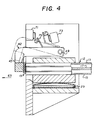
- cassette 12, Fig. 4 comprises a shell having upper and lower panels 13,15, Fig. 4.
- a photographic plate or element 17, Fig. 4, of the photostimulable phosphorus type is disposed therein and is secured to a removable end cap 19, Fig. 4.
- End cap 19 includes a latching mechanism (not shown) for releasing end cap 19 and attached photographic plate 17 from the cassette 12.
- photographic plate 17 is designed to be removed with end cap 19 from cassette 12.
- the details of construction of the cassette is described in the Jeffrey C. Robertson application, EPA-92119102.9, previously referred to above.
- clamping mechanism 10 comprises a frame 11 having a pair of end plates 20,22 having an upper jaw 24 and moveable lower jaw 26 secured thereto.
- Upper jaw 24 is fixed permanently in position and has a planar registration surface 25, Fig. 3, designed to engage with the top panel or surface 13, Fig. 4, of a cassette 12 and lower jaw 26 has a registration planar surface 27, Fig. 3, designed to engage the opposite or lower surface or panel 15, Fig. 4, of cassette 12.
- registration surfaces 25,27 are planar.
- positioning of the surface of cassette 12 actually occurs by side extrusions 23, Fig. 3, of cassette being held by upper and lower jaws 24,26 which ensures the accurate vertical positioning of cassette 12.
- top panel 13 of cassette 12 is slightly bowed outward from cassette 12 such that when cassette 12 is clamped, top panel 13, Fig. 4, is forced downward by upper jaw 24.
- upper jaw 24 restrains top panel 13, Fig. 4, so that it is maintained flat and end cap 19 can be reengaged when photographic element 17 is returned to cassette 12. Without top panel 13 being bowed, it would be difficult to return photographic element 17 to cassette 12 as top panel 13 would stay down during clamping.
- Mechanism 10 is designed to clamp the forward end 47, Fig. 3 of cassette 12 between registration surfaces 25, 27, Fig. 3, of upper jaw 24 and lower jaw 26. Since side extrusions 23, Fig.
- pneumatic bladder 28 is inflated using compressed air and has a substantially elongated configuration having an inlet/outlet port 30, Fig. 2, through which a fluid, such as air, is supplied for inflating of bladder 28 and fluid can be allowed to escape so as to allow deflation of bladder 28.
- a lower mounting plate 32, Fig. 3, secured to side plates 20,22 is provided below lower jaw 26 so as to provide a resistant force to bladder 28 when inflated which will cause lower jaw 26 to move toward upper jaw 24 and thereby clamp cassette 12 therebetween. In the clamped position, cassette 12 is lifted off the shelves of the adjacent reader (not shown).
- lower jaw 26 is preferably mounted to end plates 20,22 such that, in the non operative position, forward end 33 of lower jaw 26 will be at a position slightly below rear portion 34 of lower jaw 26. In the particular embodiment illustrated, this is provided by providing a pair of cylindrical pins 35 secured to the back end of lower jaw 26 which rides in a substantially vertically elongated slot 36 formed in side plates 20,22.
- Clamping mechanism 10 further comprises a stop bar assembly 40 which provides a registration surface against which cassette 12 registers.
- stop bar assembly 40 includes a pair of arms 42 having a rear portion 44 which is pivotally mounted to end plates 20,22. Arms 42 each have a general L-shaped configuration, with short legs 43 of arms 42 facing downward. The ends of legs 43 are connected to a stop bar 45 which is designed to extend along the length of the front surface 47 of cassette 12. Stop bar 45 includes a plurality registration surface 46 for mating against the front surface 47 of cassette 12. Arms 42 are movable between an engaged position as illustrated in solid lines in Figures 3 and 4 to a non-engaged position illustrated by phantom lines.
- registration surface 46 is provided with a plurality of switches 48 which are designed to engage front surface 47 of cassette 12. In the particular embodiment illustrated, two switches 48 are provided on stop bar 45, however, any desired number may be used.
- switches 48 will be depressed, thus providing a signal to microprocessor control unit 65, Fig. 5, which controls the operation of the reader.
- Microprocessor 65 is connected to various elements for controlling the operation of the reader as is customarily done in similar prior art devices.
- microprocessor control unit 65 does not sense that microswitches 48 have been properly depressed, a message or signal can be provided to the operator that a particular condition has not been met and the reader can be prevented from any further operation until cassette 12 has been properly aligned within the clamping mechanism 10.
- switches 48 provide a valuable function in determining whether or not cassette 12 has been properly located to allow extraction of photographic element 17. Switches 48 are positioned so that both large and small cassettes may be properly monitored.
- An optional side sensing switch (not shown) may be provided in one of end plates 20,22 for detecting if one of side extrusions 23 of cassette 12 has been properly registered therewith.
- FIG. 5 there is illustrated a schematic diagram of the pneumatic system used to control bladder 28 and pneumatic cylinder 50.
- An appropriate sized air compressor 52 is provided for providing fluid pressure to pneumatic cylinder 50 and bladder 28.
- a pressure regulator 54 is used to regulate the pressure to bladder 28.
- bladder 28 is limited to pressures of approximately 7 psi. However, the fluid pressure may be varied as desired.
- valves 56,58 are provided.
- Valve 58 in the embodiment shown, controls pressurization of bladder 28 while valve 56 controls the exhaust of fluid pressure therein when deflation is desired.
- Appropriate switches 57 and 59 are provided for controlling valves 56,58, respectively.
- Switches 57,59 are preferably controlled by microprocessor control unit 65 which determines when bladder 28 should be inflated or deflated. When it is desired to inflate bladder 28, switch 59 is energized so as to open valve 58 to allow fluid pressure to enter bladder 28 and switch 57 is energized so that valve 56 is closed.
- switch 59 When the appropriate pressure has been provided to bladder 28, switch 59 is activated to close valve 58, thus maintaining the desired pressure within bladder 28. When it is desired to exhaust the fluid pressure from bladder 28 so as to release cassette 12, switch 59 is activated so that valve 56 allows fluid to escape.
- a pair of valves 60,62 are provided for controlling the action of pneumatic cylinder 50.
- Appropriate switches 61,63 are provided for controlling valves 60,62, respectively.
- Switches 61,63 are also controlled by microprocessor control unit 65 for properly positioning stop bar assembly 40 as required.
- valve 60 is activated so as to provide fluid pressure on cylinder 50 for driving drive piston rod 64 to the extended position such that arms 42 rotate about pivot point 49 thus moving registration surface 46 to the engaged position.
- valve 54 When it is desired to move stop bar 45 to the non-engaged position, valve 54 is energized which drives piston rod 64 in the opposite direction causing arms 42 to be placed in the retracted position as illustrated by phantom lines in Figures 3 and 4.
- a pair of switches 71,73 are provided for sensing an action member 75 attached to one of arms 42.
- switch 71 is activated to provide a signal to microprocessor or control unit 65 when stop bar 45 is in the operative position for receiving a cassette and switch 73 provides an appropriate signal to microprocessor control unit 65 when stop bar 45 is in the retracted, non-operative position suitable for allowing the extraction of plate 17 from cassette 12 in the direction, as indicated by arrow 63.
- Clamping mechanism 10 is further provided with a mounting plate 80 for mounting the mechanism to the reader.
- mounting plate 80 is provided with a plurality of opening/slots 81 for receiving bolts (not shown) for securing the mechanism to the reader.
- mechanism 10 may be secured to the reader in any manner desired.
- switches 57,59 are energized so as to maintain bladder 28 in the pressurized state. Thereafter, arms 42 of stop bar assembly 40 are moved to the non-engaged position as illustrated by phantom line in Figures 3 and 4. This is accomplished by appropriately activating switches 61,63 so as to place valves 60,62 in the condition causing fluid pressure to be provided to cylinder 50 such that stop bar 45 is moved to the position illustrated by phantom lines in Figures 3 and 4, thus allowing removal of the photographic element in a direction parallel to the cassette as shown by arrow 63.
- Photographic element 17 and associated end cap 19 are removed from the end of cassette 12 by an extraction mechanism (not shown) provided in the reader and element 17 is read by the reader as discussed in the patent of Roger S. Brahm and James Lattimore, previously referred to herein.
- Clamping mechanism 10 is maintained in the clamped position until the photographic element is returned within cassette 12.
- arms 42 are returned to the engaged position and bladder 28 is deflated.
- cassette 12 is either removed manually, or by an adjacent automatic loader (not shown). The process is repeated as desired.
- lower jaw 26 is moved into the clamping position by use of pneumatic means.
- pneumatic means other means may be employed.
- a camming mechanism (not shown) could be used to move lower jaw 26 between the clamping and non clamping positions.
- a cam can be rotatably mounted to frame 11 so that it can be rotated, the cam having an outer surface engaging the bottom of moveable jaw 26 so that when the cam is rotated, jaw member 26 will move between the unclamped position shown in Figure 3 to the clamped position shown in Figure 4.
- the present invention provides a reliable clamping mechanism for cassettes and/or pallets containing cassettes, allows quick and easy registration of the cassette, is easy and low cost to manufacture and assists in isolating the transmission vibrations through the cassette.
Claims (11)
- Dispositif (10) destiné à serrer une cassette (12) contenant un élément photosensible (17), comprenant :caractérisé en ce queun cadre (11),un levier de blocage (45) monté de façon mobile sur le cadre (11) afin de se déplacer entre une position fonctionnelle dans laquelle le levier de blocage (45) est en contact d'alignement avec l'extrémité antérieure de la cassette (12) et une position non fonctionnelle, le levier de blocage (45) comportant une surface d'alignement (46) destinée à aligner l'extrémité antérieure (47) de la cassette (12),un premier élément de mâchoire (24) fixé au cadre (11), le premier élément de mâchoire (24) comportant une seconde surface d'alignement (25) destinée à venir en contact avec une première face de la cassette (12),un second élément de mâchoire mobile (26) pouvant être déplacé entre une position de serrage et une position de non-serrage, le second élément de mâchoire (26) comportant une surface de serrage (27) destinée à venir en contact avec une seconde face de la cassette (12) opposée à la première face de la cassette (12) de manière à serrer la cassette (12) entre les premier et second éléments de mâchoire (24, 26) lorsque le second élément de mâchoire (26) se trouve dans la position de serrage,un moyen destiné à déplacer le second élément de mâchoire mobile (26) entre les positions de serrage et de non-serrage,ledit levier de blocage (45) est écarté de la position fonctionnelle lorsque ledit second élément de mâchoire (26) se trouve dans ladite position de serrage, de sorte que ladite cassette (12) est supportée uniquement par lesdits éléments de mâchoire (24, 26) afin de permettre l'extraction de l'élément photosensible par l'intermédiaire de l'extrémité antérieure de la cassette.
- Dispositif selon la revendication 1, dans lequel ledit moyen destiné à déplacer le second élément de mâchoire mobile (26) comprend une vessie pneumatique (28) placée à proximité du second élément de mâchoire mobile (26), qui peut être gonflée suivant une configuration qui amène le second élément de mâchoire (26) à se déplacer depuis la position de non-serrage jusqu'à une position de serrage, de façon que la cassette (12) soit serrée entre les premier et second éléments de mâchoire (24, 26).
- Dispositif selon la revendication 1, dans lequel le levier de blocage (45) comprend un moyen de détection (48) destiné à déterminer quand la cassette (12) a été calée de façon appropriée contre la surface d'alignement (46).
- Dispositif (10) selon la revendication 1, dans lequel le levier de blocage (45) est monté de façon pivotante sur le dispositif (10).
- Dispositif (10) selon la revendication 1, comprenant en outre un moyen (50) destiné à déplacer le levier de blocage (45) entre les positions fonctionnelle et non fonctionnelle.
- Dispositif selon la revendication 5, dans lequel ledit moyen (50) destiné à déplacer le levier de blocage (45) comprend un moyen pneumatique.
- Dispositif (10) selon la revendication 6, dans lequel ledit moyen pneumatique comprend un vérin pneumatique (50).
- Dispositif (10) selon les revendications 1 et 2, dans lequel une plaque de montage (32) est prévue afin de s'opposer au dépiacement de la vessie (28) de manière à amener le second élément de mâchoire (26) à se déplacer en direction du premier élément de mâchoire (24).
- Dispositif (10) selon la revendication 2, dans lequel ledit moyen destiné à déplacer le second élément de mâchoire mobile (26) comprend :une source de pression pneumatique (52),des premières vannes (56, 58) en communication fluidique avec la source de pression pneumatique (52) destinées à commander la mise sous pression et le dégonflage de la vessie (28),des secondes vannes (60, 62) en communication fluidique avec la source de pression pneumatique (52) destinées à commander le déplacement du levier de blocage (45) entre les positions fonctionnelle et non fonctionnelle.
- Dispositif (10) selon la revendication 1, comprenant en outre des moyens (61, 63) destinés à détecter quand le levier de blocage (45) se trouve dans la position fonctionnelle.
- Dispositif (10) selon la revendication 1, dans lequel le moyen destiné à déplacer le second élément de mâchoire (26) comprend un ensemble à came qui déplace le second élément de mâchoire (26) entre les positions de serrage et de non-serrage.
Applications Claiming Priority (2)
| Application Number | Priority Date | Filing Date | Title |
|---|---|---|---|
| US07/981,680 US5315632A (en) | 1992-11-25 | 1992-11-25 | Cassette clamping mechanism |
| US981680 | 1992-11-25 |
Publications (2)
| Publication Number | Publication Date |
|---|---|
| EP0600244A1 EP0600244A1 (fr) | 1994-06-08 |
| EP0600244B1 true EP0600244B1 (fr) | 1998-08-26 |
Family
ID=25528572
Family Applications (1)
| Application Number | Title | Priority Date | Filing Date |
|---|---|---|---|
| EP93117711A Expired - Lifetime EP0600244B1 (fr) | 1992-11-25 | 1993-11-02 | Mécanisme de fixation de cassette |
Country Status (4)
| Country | Link |
|---|---|
| US (1) | US5315632A (fr) |
| EP (1) | EP0600244B1 (fr) |
| JP (1) | JPH06229404A (fr) |
| DE (1) | DE69320594T2 (fr) |
Families Citing this family (13)
| Publication number | Priority date | Publication date | Assignee | Title |
|---|---|---|---|---|
| US5330309A (en) * | 1992-11-25 | 1994-07-19 | Eastman Kodak Company | Reader having cassette locating and unlatching mechanism |
| US5493128A (en) * | 1994-08-25 | 1996-02-20 | Eastman Kodak Company | Method and apparatus for indexing cassettes |
| DE19523170A1 (de) * | 1995-06-26 | 1997-01-02 | Siemens Ag | Filmkassettenlade für Röntgenfilme |
| EP1640800B1 (fr) * | 2004-09-22 | 2008-08-20 | Agfa-Gevaert HealthCare GmbH | Dispositif de lecture d'information radiographique stockée dans une plaque à mémoire luminescente |
| US7368747B2 (en) * | 2004-12-17 | 2008-05-06 | Carestream Health, Inc. | Short U-flow multicassette autoloader for a storage phosphor reader |
| US20060195064A1 (en) * | 2005-02-28 | 2006-08-31 | Fresenius Medical Care Holdings, Inc. | Portable apparatus for peritoneal dialysis therapy |
| US7935074B2 (en) * | 2005-02-28 | 2011-05-03 | Fresenius Medical Care Holdings, Inc. | Cassette system for peritoneal dialysis machine |
| US7456419B2 (en) | 2006-08-21 | 2008-11-25 | Carestream Health, Inc. | Radiation imaging cassette |
| US20080058712A1 (en) * | 2006-08-31 | 2008-03-06 | Plahey Kulwinder S | Peritoneal dialysis machine with dual voltage heater circuit and method of operation |
| DE102008013918A1 (de) * | 2008-03-12 | 2009-09-17 | Thoms, Michael, Prof. Dr. | Speicherfolienzuführung |
| US8720913B2 (en) * | 2009-08-11 | 2014-05-13 | Fresenius Medical Care Holdings, Inc. | Portable peritoneal dialysis carts and related systems |
| DE102010053973A1 (de) | 2010-12-09 | 2012-06-14 | Fresenius Medical Care Deutschland Gmbh | Medizinisches Gerät mit einer Heizung |
| US9186449B2 (en) | 2011-11-01 | 2015-11-17 | Fresenius Medical Care Holdings, Inc. | Dialysis machine support assemblies and related systems and methods |
Citations (4)
| Publication number | Priority date | Publication date | Assignee | Title |
|---|---|---|---|---|
| EP0522316A1 (fr) * | 1991-07-11 | 1993-01-13 | Eastman Kodak Company | Chargeur automatique pour cassettes de film |
| EP0544138A2 (fr) * | 1991-11-27 | 1993-06-02 | Eastman Kodak Company | Cassette à rayons X avec un élément photographique amovible |
| US5328019A (en) * | 1992-11-25 | 1994-07-12 | Eastman Kodak Company | Autoloader for cassettes and/or pallet |
| US5330309A (en) * | 1992-11-25 | 1994-07-19 | Eastman Kodak Company | Reader having cassette locating and unlatching mechanism |
Family Cites Families (22)
| Publication number | Priority date | Publication date | Assignee | Title |
|---|---|---|---|---|
| US3150263A (en) * | 1962-12-05 | 1964-09-22 | Kenneth G Catlin | Cassette unloading and reloading machine |
| FR1362137A (fr) * | 1963-06-11 | 1964-05-29 | Man Ets De | Dispositif de serrage pour la fixation de cassettes sur un chariot susceptible de se déplacer dans un appareil de prise de vues en série d'appareils de radiographie |
| US3850316A (en) * | 1974-01-28 | 1974-11-26 | Columbia Machine | Apparatus for loading and unloading vertically stacked racks |
| EP0017273B1 (fr) * | 1979-03-30 | 1983-09-14 | Agfa-Gevaert N.V. | Dispositif de positionnement de cassettes radiographiques |
| US4514958A (en) * | 1982-11-24 | 1985-05-07 | E. I. Du Pont De Nemours And Company | Automatic X-ray film cassette unloader and reloader |
| US4538293A (en) * | 1983-02-23 | 1985-08-27 | Cutter James W | X-ray film cassette holder |
| DE3306575A1 (de) * | 1983-02-25 | 1984-08-30 | Winkler & Dünnebier, Maschinenfabrik und Eisengießerei GmbH & Co KG, 5450 Neuwied | Kombiniertes entstapel-rueckstapelgeraet als stapelbeschickungsanlage |
| US4540325A (en) * | 1983-04-18 | 1985-09-10 | Heisler Raymond A | Upstacker apparatus with biased gripping means |
| US4814618A (en) * | 1984-03-16 | 1989-03-21 | Fuji Photo Film Co., Ltd. | Radiation image read-out method and radiation image recording read-out apparatus |
| JPH0690407B2 (ja) * | 1985-07-24 | 1994-11-14 | 富士写真フイルム株式会社 | 放射線画像情報記録読取装置 |
| DE3681872D1 (de) * | 1985-10-17 | 1991-11-14 | Fuji Photo Film Co Ltd | Kassette fuer bildinformationsaufnahmetraeger, mechanismus zum entfernen des bildinformationsaufnahmetraegers aus der kassette und vorrichtung zur wiedergabe der bildinformation. |
| US4761554A (en) * | 1986-02-03 | 1988-08-02 | Fuji Photo Film Co., Ltd. | Radiation image read-out apparatus |
| US4789782A (en) * | 1986-08-15 | 1988-12-06 | Fuji Photo Film Co., Ltd. | Radiation image recording and reproducing system |
| US4845733A (en) * | 1987-05-01 | 1989-07-04 | Liebel-Flarsheim Company | Cassette film transport |
| US4904868A (en) * | 1987-08-19 | 1990-02-27 | Fuji Photo Film Co., Ltd. | Radiation image read-out apparatus and stimulable phosphor sheet composite member for the same |
| DE3731203A1 (de) * | 1987-09-17 | 1989-03-30 | Agfa Gevaert Ag | Verfahren zur handhabung von roentgenaufnahmekassetten mit einer phosphorbeschichteten folie und zur durchfuehrung des verfahrens geeignete lesestation |
| DE3801397A1 (de) * | 1988-01-20 | 1989-08-03 | Grau Gmbh & Co Holdingges | Greifer |
| JPH07101285B2 (ja) * | 1988-06-30 | 1995-11-01 | 富士写真フイルム株式会社 | 放射線画像情報読取装置 |
| FR2646340A1 (fr) * | 1989-04-28 | 1990-11-02 | Gen Electric Cgr | Porte-cassette adaptable en dimension et en position pour mammographie |
| SE505062C2 (sv) * | 1989-06-06 | 1997-06-16 | Amada Co Ltd | Sätt och anordning för in- och utmatning av arbetsstycken vid en plåtbearbetningsmaskin |
| FR2659221B1 (fr) * | 1990-03-08 | 1992-05-22 | General Electric Cgr Sa | Dispositif de mise en place de cassettes pour mammographes. |
| US5062130A (en) * | 1990-11-26 | 1991-10-29 | Liebel-Flarsheim Company | X-ray film cassette transport |
-
1992
- 1992-11-25 US US07/981,680 patent/US5315632A/en not_active Expired - Lifetime
-
1993
- 1993-11-02 DE DE69320594T patent/DE69320594T2/de not_active Expired - Fee Related
- 1993-11-02 EP EP93117711A patent/EP0600244B1/fr not_active Expired - Lifetime
- 1993-11-24 JP JP5293510A patent/JPH06229404A/ja active Pending
Patent Citations (4)
| Publication number | Priority date | Publication date | Assignee | Title |
|---|---|---|---|---|
| EP0522316A1 (fr) * | 1991-07-11 | 1993-01-13 | Eastman Kodak Company | Chargeur automatique pour cassettes de film |
| EP0544138A2 (fr) * | 1991-11-27 | 1993-06-02 | Eastman Kodak Company | Cassette à rayons X avec un élément photographique amovible |
| US5328019A (en) * | 1992-11-25 | 1994-07-12 | Eastman Kodak Company | Autoloader for cassettes and/or pallet |
| US5330309A (en) * | 1992-11-25 | 1994-07-19 | Eastman Kodak Company | Reader having cassette locating and unlatching mechanism |
Also Published As
| Publication number | Publication date |
|---|---|
| JPH06229404A (ja) | 1994-08-16 |
| DE69320594T2 (de) | 1999-04-01 |
| US5315632A (en) | 1994-05-24 |
| DE69320594D1 (de) | 1998-10-01 |
| EP0600244A1 (fr) | 1994-06-08 |
Similar Documents
| Publication | Publication Date | Title |
|---|---|---|
| EP0600244B1 (fr) | Mécanisme de fixation de cassette | |
| JP2597799B2 (ja) | 印刷機の版胴に版を供給する装置 | |
| EP0520594B1 (fr) | Dispositif pour remplacer le cliché d'impression dans une machine à imprimer | |
| JPH026442Y2 (fr) | ||
| US4811547A (en) | Device for loading and unloading X-ray film cassettes | |
| US5207414A (en) | Media handling system for photoplotter and method of use | |
| US5328019A (en) | Autoloader for cassettes and/or pallet | |
| JPS6012616B2 (ja) | 自動製版カメラ | |
| US5484139A (en) | System for handling curved form media and cassette therefor | |
| JPH1039028A (ja) | フィルム状の試料を取扱い自動的に位置決めするための装置 | |
| US5558320A (en) | Lifting shoe for media handling and related cassette media holder | |
| US4760641A (en) | Apparatus for loading and unloading x-ray film cassettes | |
| EP0845701B1 (fr) | Gouttière ajustable pour film rayons-x | |
| JP2594507Y2 (ja) | 試料装着補助装置 | |
| JPH08328175A (ja) | 走査キヤリツジ及びベルトを具えるpslラジオグラフイーのための走査装置 | |
| US5394220A (en) | Vacuum blanket for pin registration | |
| JP2974849B2 (ja) | 自動製版方法及び装置 | |
| US5481333A (en) | Latchable vacuum blanket frame assembly | |
| JPH0248838Y2 (fr) | ||
| JP2705490B2 (ja) | X線撮影装置 | |
| US5911415A (en) | Collecting cassette for use with a media sheet handling system | |
| JPH04347849A (ja) | カセッテ搬送方法およびその装置 | |
| JPH1039438A (ja) | X線画像撮影装置 | |
| GB2315339A (en) | Light-tight sheet supply cassette | |
| JPH10260504A (ja) | シート状感光材料の装填方法および装置 |
Legal Events
| Date | Code | Title | Description |
|---|---|---|---|
| PUAI | Public reference made under article 153(3) epc to a published international application that has entered the european phase |
Free format text: ORIGINAL CODE: 0009012 |
|
| AK | Designated contracting states |
Kind code of ref document: A1 Designated state(s): DE FR GB IT |
|
| 17P | Request for examination filed |
Effective date: 19941020 |
|
| 17Q | First examination report despatched |
Effective date: 19951018 |
|
| GRAG | Despatch of communication of intention to grant |
Free format text: ORIGINAL CODE: EPIDOS AGRA |
|
| GRAG | Despatch of communication of intention to grant |
Free format text: ORIGINAL CODE: EPIDOS AGRA |
|
| GRAH | Despatch of communication of intention to grant a patent |
Free format text: ORIGINAL CODE: EPIDOS IGRA |
|
| GRAH | Despatch of communication of intention to grant a patent |
Free format text: ORIGINAL CODE: EPIDOS IGRA |
|
| GRAA | (expected) grant |
Free format text: ORIGINAL CODE: 0009210 |
|
| ITF | It: translation for a ep patent filed |
Owner name: BARZANO' E ZANARDO MILANO S.P.A. |
|
| AK | Designated contracting states |
Kind code of ref document: B1 Designated state(s): DE FR GB IT |
|
| REF | Corresponds to: |
Ref document number: 69320594 Country of ref document: DE Date of ref document: 19981001 |
|
| ET | Fr: translation filed | ||
| PLBE | No opposition filed within time limit |
Free format text: ORIGINAL CODE: 0009261 |
|
| STAA | Information on the status of an ep patent application or granted ep patent |
Free format text: STATUS: NO OPPOSITION FILED WITHIN TIME LIMIT |
|
| 26N | No opposition filed | ||
| PGFP | Annual fee paid to national office [announced via postgrant information from national office to epo] |
Ref country code: GB Payment date: 20001004 Year of fee payment: 8 |
|
| PGFP | Annual fee paid to national office [announced via postgrant information from national office to epo] |
Ref country code: FR Payment date: 20001107 Year of fee payment: 8 |
|
| PG25 | Lapsed in a contracting state [announced via postgrant information from national office to epo] |
Ref country code: GB Free format text: LAPSE BECAUSE OF NON-PAYMENT OF DUE FEES Effective date: 20011102 |
|
| REG | Reference to a national code |
Ref country code: GB Ref legal event code: IF02 |
|
| GBPC | Gb: european patent ceased through non-payment of renewal fee |
Effective date: 20011102 |
|
| PG25 | Lapsed in a contracting state [announced via postgrant information from national office to epo] |
Ref country code: FR Free format text: LAPSE BECAUSE OF NON-PAYMENT OF DUE FEES Effective date: 20020730 |
|
| REG | Reference to a national code |
Ref country code: FR Ref legal event code: ST |
|
| REG | Reference to a national code |
Ref country code: FR Ref legal event code: ST |
|
| PGFP | Annual fee paid to national office [announced via postgrant information from national office to epo] |
Ref country code: DE Payment date: 20031128 Year of fee payment: 11 |
|
| PG25 | Lapsed in a contracting state [announced via postgrant information from national office to epo] |
Ref country code: DE Free format text: LAPSE BECAUSE OF NON-PAYMENT OF DUE FEES Effective date: 20050601 |
|
| PG25 | Lapsed in a contracting state [announced via postgrant information from national office to epo] |
Ref country code: IT Free format text: LAPSE BECAUSE OF NON-PAYMENT OF DUE FEES;WARNING: LAPSES OF ITALIAN PATENTS WITH EFFECTIVE DATE BEFORE 2007 MAY HAVE OCCURRED AT ANY TIME BEFORE 2007. THE CORRECT EFFECTIVE DATE MAY BE DIFFERENT FROM THE ONE RECORDED. Effective date: 20051102 |