EP0599427A1 - Static energy regulator for lighting networks with control of the quantity of the intensity and/or voltage, harmonic content and reactive energy supplied to the load - Google Patents
Static energy regulator for lighting networks with control of the quantity of the intensity and/or voltage, harmonic content and reactive energy supplied to the load Download PDFInfo
- Publication number
- EP0599427A1 EP0599427A1 EP93203290A EP93203290A EP0599427A1 EP 0599427 A1 EP0599427 A1 EP 0599427A1 EP 93203290 A EP93203290 A EP 93203290A EP 93203290 A EP93203290 A EP 93203290A EP 0599427 A1 EP0599427 A1 EP 0599427A1
- Authority
- EP
- European Patent Office
- Prior art keywords
- inverter
- load
- voltage
- intensity
- signal
- Prior art date
- Legal status (The legal status is an assumption and is not a legal conclusion. Google has not performed a legal analysis and makes no representation as to the accuracy of the status listed.)
- Ceased
Links
Images

Classifications
-
- H—ELECTRICITY
- H02—GENERATION; CONVERSION OR DISTRIBUTION OF ELECTRIC POWER
- H02M—APPARATUS FOR CONVERSION BETWEEN AC AND AC, BETWEEN AC AND DC, OR BETWEEN DC AND DC, AND FOR USE WITH MAINS OR SIMILAR POWER SUPPLY SYSTEMS; CONVERSION OF DC OR AC INPUT POWER INTO SURGE OUTPUT POWER; CONTROL OR REGULATION THEREOF
- H02M1/00—Details of apparatus for conversion
- H02M1/42—Circuits or arrangements for compensating for or adjusting power factor in converters or inverters
- H02M1/4208—Arrangements for improving power factor of AC input
-
- H—ELECTRICITY
- H02—GENERATION; CONVERSION OR DISTRIBUTION OF ELECTRIC POWER
- H02M—APPARATUS FOR CONVERSION BETWEEN AC AND AC, BETWEEN AC AND DC, OR BETWEEN DC AND DC, AND FOR USE WITH MAINS OR SIMILAR POWER SUPPLY SYSTEMS; CONVERSION OF DC OR AC INPUT POWER INTO SURGE OUTPUT POWER; CONTROL OR REGULATION THEREOF
- H02M5/00—Conversion of AC power input into AC power output, e.g. for change of voltage, for change of frequency, for change of number of phases
- H02M5/40—Conversion of AC power input into AC power output, e.g. for change of voltage, for change of frequency, for change of number of phases with intermediate conversion into DC
- H02M5/42—Conversion of AC power input into AC power output, e.g. for change of voltage, for change of frequency, for change of number of phases with intermediate conversion into DC by static converters
- H02M5/44—Conversion of AC power input into AC power output, e.g. for change of voltage, for change of frequency, for change of number of phases with intermediate conversion into DC by static converters using discharge tubes or semiconductor devices to convert the intermediate DC into AC
- H02M5/453—Conversion of AC power input into AC power output, e.g. for change of voltage, for change of frequency, for change of number of phases with intermediate conversion into DC by static converters using discharge tubes or semiconductor devices to convert the intermediate DC into AC using devices of a triode or transistor type requiring continuous application of a control signal
- H02M5/458—Conversion of AC power input into AC power output, e.g. for change of voltage, for change of frequency, for change of number of phases with intermediate conversion into DC by static converters using discharge tubes or semiconductor devices to convert the intermediate DC into AC using devices of a triode or transistor type requiring continuous application of a control signal using semiconductor devices only
- H02M5/4585—Conversion of AC power input into AC power output, e.g. for change of voltage, for change of frequency, for change of number of phases with intermediate conversion into DC by static converters using discharge tubes or semiconductor devices to convert the intermediate DC into AC using devices of a triode or transistor type requiring continuous application of a control signal using semiconductor devices only having a rectifier with controlled elements
-
- H—ELECTRICITY
- H05—ELECTRIC TECHNIQUES NOT OTHERWISE PROVIDED FOR
- H05B—ELECTRIC HEATING; ELECTRIC LIGHT SOURCES NOT OTHERWISE PROVIDED FOR; CIRCUIT ARRANGEMENTS FOR ELECTRIC LIGHT SOURCES, IN GENERAL
- H05B41/00—Circuit arrangements or apparatus for igniting or operating discharge lamps
- H05B41/14—Circuit arrangements
- H05B41/26—Circuit arrangements in which the lamp is fed by power derived from DC by means of a converter, e.g. by high-voltage DC
- H05B41/28—Circuit arrangements in which the lamp is fed by power derived from DC by means of a converter, e.g. by high-voltage DC using static converters
-
- H—ELECTRICITY
- H02—GENERATION; CONVERSION OR DISTRIBUTION OF ELECTRIC POWER
- H02M—APPARATUS FOR CONVERSION BETWEEN AC AND AC, BETWEEN AC AND DC, OR BETWEEN DC AND DC, AND FOR USE WITH MAINS OR SIMILAR POWER SUPPLY SYSTEMS; CONVERSION OF DC OR AC INPUT POWER INTO SURGE OUTPUT POWER; CONTROL OR REGULATION THEREOF
- H02M1/00—Details of apparatus for conversion
- H02M1/42—Circuits or arrangements for compensating for or adjusting power factor in converters or inverters
- H02M1/4208—Arrangements for improving power factor of AC input
- H02M1/4275—Arrangements for improving power factor of AC input by adding an auxiliary output voltage in series to the input
-
- Y—GENERAL TAGGING OF NEW TECHNOLOGICAL DEVELOPMENTS; GENERAL TAGGING OF CROSS-SECTIONAL TECHNOLOGIES SPANNING OVER SEVERAL SECTIONS OF THE IPC; TECHNICAL SUBJECTS COVERED BY FORMER USPC CROSS-REFERENCE ART COLLECTIONS [XRACs] AND DIGESTS
- Y02—TECHNOLOGIES OR APPLICATIONS FOR MITIGATION OR ADAPTATION AGAINST CLIMATE CHANGE
- Y02B—CLIMATE CHANGE MITIGATION TECHNOLOGIES RELATED TO BUILDINGS, e.g. HOUSING, HOUSE APPLIANCES OR RELATED END-USER APPLICATIONS
- Y02B70/00—Technologies for an efficient end-user side electric power management and consumption
- Y02B70/10—Technologies improving the efficiency by using switched-mode power supplies [SMPS], i.e. efficient power electronics conversion e.g. power factor correction or reduction of losses in power supplies or efficient standby modes
Definitions
- the present invention refers to a static energy regulator for lighting networks with control of the quantity of the intensity and/or voltage, harmonic content and reactive energy supplied to the load. It consists of a static feed system whose purpose is to totally control the characteristics of the energy gupplied to an electric load. These characteristics are:
- This invention is developed specifically for the control of the energy supplied to street lighting networks, nonetheless, it can be generally applied to any types of loads whether or not they are linear, and with any power factor.
- This reduction of luminous flux is basically carried out by means of two systems: reduction in each light spot or generally in the head of each lighting sector.
- Adjustment in the light spot is done by means of the installation, in each luminaire, of special double level reactors switched by a relay.
- the operation of this relay can be done from the control panel of the lighting sector by means of special wiring, or else by installing an electronic timer in each light spot. If it is done from the control panel of the sector, there is the inconvenience of the need of additional wiring, while, if it is done by means of a timer, there is the inconvenience of the difficulty and little flexibility in programming each individual timer.
- Adjustment at the head of the feed voltage of an entire sector is done by means of autotransformers whose dimensions and weights are very high, which implies a serious difficulty for the installation in control panels. Besides, the presence of moveable electromechanical components reduces reliability of equipment that is to operate in adverse environmental conditions.
- U.S. patent 4,924,150 "POWER-LINE CONTROL SYSTEM,” teaches a device that is inserted between the feed source and the load and that permits the control of the waveform of the current supplied, but without any contribution or reduction of active energy.
- the inverter placed between the feed and the load does not contribute to or absorbe net energy from or towards the d.c. feed thereof, without the energy absorbed in certain parts of the feed cycle being returned in others, for the purpose of controlling the waveform of the current.
- French patent 2,668,674 "CIRCUIT DE REGLAJE D' INTENSITE LUMINEUSE POUR INSTALLATION D'ECAIRAGE UTILISANT DES LAMPES OU TUBES A DECHARGE," teaches an adjustment system comprised of a three-phase transformer series connected between the feed phases and the load. The secondary of this transformer is connected to a diode rectifier, that provides continuous current, which, by means of a thyristor controlled bridge, is returned to the input through some reactors.
- This assembly according to the specification of said patent, varies the effective value of the voltage delivered to the lamps, but keeping the crest value constant.
- the invention consists of a static energy regulator for lighting networks with control of the quantity of the intensity and/or voltage, harmonic content and reactive energy supplied to the load, that controls the waveform of the intensity delivered to the load and that therefore achieves the control of the value of active energy supplied to the load, and the compensation of the power factor of the load, invalidating the reactive energy consumed. All of this permits the energy consumption to be kept at the desired value thus compensating the variations in the supply, lengthening the working life of the lamps, and reducing the service operating cost.
- the equipment of the invention consists of a device that is inserted between the feed network and the load.
- This device has to be capable of controlling in an exact manner the intensity that flows through it, the quantity, as well as in waveform, as in phase. If the in-phase senusoidal intensity is controlled with the feed and observing the corresponding voltage and intensity vector diagrams, for inductive loads as well as for capacitive loads, it is observed that said device supplies the reactive energy required for the load, whereby the power factor thereof is compensated for, so that, from the feed source, the intensity is always in phase with the voltage. Besides, the active energy consumed by the cited device is converted into current also in phase with the feed voltage and returned to the input. This means that, except for losses of the device, the feed source only the net active energy required by the load is supplied, without delivering any reactive energy.
- the device that is going to be commented on has an inverter, connected to the load, operating in accordance with the voltage source method, and with high frequency pulse width modulation.
- This inverter is capable of controlling the energy flux through it in the four quadrants of the voltage-current plane, by means of a hysteresis controller.
- This controller permanently compares the value of an indicative wave with the real intensity wave that flows through the inverter.
- the controller modulates the triggering of the semiconductors of the inverter so that the real intensity closely follows the indicative waveform.
- the device has another inverter identical to the previous one but parallel connected to the feed voltage, so that it can absorb or inject intensity into it.
- the reactive energy converts into a flow of current to and from a continuous current capacitor connected between the two inverters, increasing the voltage of said capacitor in some parts of the cycle and reducing in others, but with a null net energy balance.
- the active energy converts into a positive net increase of voltage in the capacitor , if it is absorbed by the inverter connected to the load, and by a net reduction, if it is conveyed by said inverter.
- the voltage in the capacitor is compared with a set value, and the difference is applied to a multiplier that amplifies an in-phase sinusoidal reference with the feed. If the voltage in the condenser rises, the difference applied in the multiplier upon the sinusoidal reference, causes an intensity indication determined by the output of this multiplier to increase; while if the voltage in the capacitor is low, the difference applied in the multiplier makes said intensity indication drop.
- This indication of intensity is compared with the real intensity supplied by the converter connected to the feed, modulating the triggering of the semiconductors thereof, so that the real intensity accurately follows the waveform of the indication of intensity.
- an active energy flux towards the capacitor makes the intensity injected in the input of the system increase, while a negative energy flux makes the direction of said intensity reverse. Therefore, the active energy that is taken from the system in the inverter connected to the load is reinjected in the input of the inverter connected to the feed. On the contrary, if it is necessary to furnish active energy to the system by the inverter connected to the load, to keep the output intensity set, this energy is absorbed at the input by the inverter connected to the feed.
- the energy flux that is supplied to the load is perfectly controlled, controlling all of the characeristics thereof.
- the system allows the voltage or intensity supplied to the lamps to be controlled, having an effect on the input only the required active net energy, and generating inside the reactive energy; whereby the advantages of a lower consumption and longer working life of the lamps is achieved, reducing the operating cost of said lighting networks.
- Figure 1. It represents a simplified electric diagram of the static energy regulator of the invention, showing its operating principle for a single phase of feed voltage.
- Figure 2. It represents a vector diagram of the voltages of the circuit of figure 1 for an inductive load.
- Figure 3. It represents a vector diagram of the voltages of the circuit of figure 1 for a capacitive load.
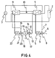
- Figure 4.- It represents the electric diagram of the static energy regulator of the present invention for a phase of the feed voltage.
- the static energy regulator for lighting networks with control of the quantity of the intensity and/or voltage, harmonic content and reactive energy supplied to the load consists of a device (1) that is inserted between the load (2) and the feed (3) so that the voltage drop UC in device (1) plus the voltage drop UL in the load (2), is equal to the voltage UE of the feed (3); and the intensity IC if the device (1) plus the intensity IE of feed (3), is equal to the intensity IL in the load (2.)
- Device (1) is capable of controlling the intensity IL in the load (2) that passes through it. This control refers to the quantity, as well as to the waveform and to the phase.
- this intensity IL is sinusoidal, it is in phase with the voltage UE of the feed (3), and W being the shift between said voltage UE and voltage UL in the load (2), a vector diagram like the one of figure 2 is obtained when the load (2) has an inductive cos W; while if the load (2) has a capacitive cos W, a vector diagram like the one in figure 3 is obtained.
- the power consumed by load (2) is represented by segment o-a in the active part thereof, and by segment a-b in the reactive part thereof.
- the power absorbed by device (1) remains represented by segment a-c in the active part thereof and by segment b-a in the reactive part thereof.
- the feed source (3) only delivers the net active energy required by the load (2), and no reactive energy.
- This inverter (4) is capable of controlling the energy flux through it in the four quadrants of the V-I plane, by means of connection thereof to a controller by hysteresis 5.
- Said controller 5 continuously compares the value of an indicative wave (6) with the real intensity wave (7) tha flows through the inverter (4.) In terms of the instant differences (9), obtained by the subtractor (8), between said signals (6) and (7), the controller (5) modulates the triggering of the semiconductors of the inverter (4) so that the signal (7) correctly follows the waveform of the indicative signal (6).
- the reactive energy converts into a flow of current to and from a capacitor (10) of dirrect current connected to the inverter (4), increasing the voltage thereof in some parts of the cycle and reducing it in others, but with a null energy balance. Nonetheless, the active energy converts into a positive net increase of voltage in the capacitor (10) when it is absorbed by the inverter (4) and in a net reduction when it is conveyed by the inverter (4.)
- the device (1) also has another part comprised of another inverter (11) identical to the inverter (4) but parallel connected to the feed to the feed (3), so that it can inject or absorb intensity therein or therefrom.
- the voltage (12) in the capacitor (10) is comparied with a set voltage (13) both having a subtractor (14.)
- the difference (15) between said voltages (12) and (13) is taken to a multiplier (16) that amplifier a sinusoidal reference (17) in phase with the feed (3.) If the voltage (12) in the capacitor (10) rises, the difference signal (15) or error signal applied to the sinusoidal reference (17) makes the output signal of the multiplier (16) rise, which is another intensity indicative signal (18.) On the contrary, if the voltage (12) in the capacitor (10) drops, the difference signal (15) makes the intensity indicative signal (18) drop.
- This indicative signal (18) is compared with the real intensity (19) that the inverter (11) supplies, taking both signals (18) and (19) to the substractor (20.)
- the difference (21) between them is taken to another controller by hysteresis (22) which connected to inverter (11) is responsible for modulating the triggering of the semiconductors thereof so that the real intensity (19) correctly follows the waveform of the indicative signal (18.)
- the result of the configuration and the operation that have been put forth consists of an active energy flux towards the capacitor (10) makes the intensity (19) injected in the input of the system rise, while a negative energy flux reverses the direction of this intensity (19.) Therefore, the active energy that is substracted from the system in the inverter (4) is reinjected into the input of the inverter (11.) Nonetheless, when it is necessary to provide active energy to the system by the invert (4) to keep the output intensity (7), this energy is absorbed at the input by the inverter (11.)
- the energy flux that is supplied to the load (2) is perfectly controlled
Landscapes
- Engineering & Computer Science (AREA)
- Power Engineering (AREA)
- Control Of Electrical Variables (AREA)
- Circuit Arrangement For Electric Light Sources In General (AREA)
- Inverter Devices (AREA)
- Circuit Arrangements For Discharge Lamps (AREA)
Applications Claiming Priority (2)
| Application Number | Priority Date | Filing Date | Title |
|---|---|---|---|
| ES09202407A ES2070051B1 (es) | 1992-11-27 | 1992-11-27 | Regulador estatico de energia para redes de alumbrado con control sobre la magnitud de la intensidad y/o voltaje, contenido de armonicos y energia reactiva suministrada a la carga. |
| ES9202407 | 1992-11-27 |
Publications (1)
| Publication Number | Publication Date |
|---|---|
| EP0599427A1 true EP0599427A1 (en) | 1994-06-01 |
Family
ID=8278935
Family Applications (1)
| Application Number | Title | Priority Date | Filing Date |
|---|---|---|---|
| EP93203290A Ceased EP0599427A1 (en) | 1992-11-27 | 1993-11-25 | Static energy regulator for lighting networks with control of the quantity of the intensity and/or voltage, harmonic content and reactive energy supplied to the load |
Country Status (4)
| Country | Link |
|---|---|
| US (1) | US5450311A (enExample) |
| EP (1) | EP0599427A1 (enExample) |
| JP (1) | JPH06296371A (enExample) |
| ES (1) | ES2070051B1 (enExample) |
Cited By (1)
| Publication number | Priority date | Publication date | Assignee | Title |
|---|---|---|---|---|
| GB2405540A (en) * | 2003-08-27 | 2005-03-02 | Ron Shu-Yuen Hui | Dimming control of lamps and electrical lighting systems |
Families Citing this family (8)
| Publication number | Priority date | Publication date | Assignee | Title |
|---|---|---|---|---|
| JP2791273B2 (ja) * | 1993-09-07 | 1998-08-27 | 株式会社東芝 | 電力変換装置 |
| JP3311214B2 (ja) * | 1995-09-05 | 2002-08-05 | 東京電力株式会社 | 電力変換装置の制御装置 |
| JP3232431B2 (ja) * | 1995-09-08 | 2001-11-26 | 株式会社日立製作所 | 電力変換装置 |
| TWI291282B (en) * | 2002-06-03 | 2007-12-11 | Fuji Electric Co Ltd | Power converter |
| GB2418786B (en) * | 2004-10-01 | 2006-11-29 | Energy Doubletree Ltd E | Dimmable lighting system |
| ES2325730B2 (es) * | 2009-02-20 | 2010-03-01 | Universidad Politecnica De Madrid | Sistema de regulacion continua de alumbrado. |
| CN108541107B (zh) * | 2018-04-28 | 2024-04-12 | 赛尔富电子有限公司 | 一种照明负载异常检测装置及对应的照明系统 |
| US12567800B2 (en) * | 2024-04-16 | 2026-03-03 | Semiconductor Components Industries, Llc | Multi-mode control method for PFC switching power supply |
Citations (1)
| Publication number | Priority date | Publication date | Assignee | Title |
|---|---|---|---|---|
| EP0498651A2 (en) * | 1991-02-08 | 1992-08-12 | General Electric Company | High power factor power supply |
Family Cites Families (8)
| Publication number | Priority date | Publication date | Assignee | Title |
|---|---|---|---|---|
| JPH0636676B2 (ja) * | 1985-03-01 | 1994-05-11 | 勲 高橋 | Pwmインバ−タの制御方法 |
| US4887007A (en) * | 1987-02-18 | 1989-12-12 | U.S. Philips Corporation | DC-AC converter for supplying a gas and/or vapour discharge lamp |
| US4879639A (en) * | 1987-05-11 | 1989-11-07 | Fuji Electric Co., Ltd. | Power converter for driving an AC motor at a variable speed |
| JP2680345B2 (ja) * | 1988-05-09 | 1997-11-19 | 株式会社東芝 | Pwm制御による電源装置 |
| GB2226898B (en) * | 1988-12-20 | 1992-08-12 | Strand Lighting Ltd | Electric lighting and power controllers therefor |
| GB2226431B (en) * | 1988-12-20 | 1992-08-12 | Strand Lighting Ltd | Electric lighting and power controllers therefor |
| DE3905261A1 (de) * | 1989-02-21 | 1990-08-23 | Siemens Ag | Verfahren und einrichtung zur stabilisation eines elektrischen versorgungsnetzes |
| US5567988A (en) * | 1993-08-13 | 1996-10-22 | Lsi Logic Corporation | Integrated circuit interconnect structure with back reflection suppressing electronic "speed bumps" |
-
1992
- 1992-11-27 ES ES09202407A patent/ES2070051B1/es not_active Expired - Fee Related
-
1993
- 1993-11-24 US US08/157,985 patent/US5450311A/en not_active Expired - Fee Related
- 1993-11-25 EP EP93203290A patent/EP0599427A1/en not_active Ceased
- 1993-11-29 JP JP5297902A patent/JPH06296371A/ja not_active Withdrawn
Patent Citations (1)
| Publication number | Priority date | Publication date | Assignee | Title |
|---|---|---|---|---|
| EP0498651A2 (en) * | 1991-02-08 | 1992-08-12 | General Electric Company | High power factor power supply |
Non-Patent Citations (2)
| Title |
|---|
| KHERALUWALA ET AL.: "A fast response high power factor converter with a single power stage", PESC'91, 27 June 1991 (1991-06-27), BOSTON, pages 769 - 779, XP000278419, DOI: doi:10.1109/PESC.1991.162763 * |
| ROUND ET AL.: "A controlled current inverter for active distortion compensation and power factor correction", IECON'91, 28 October 1991 (1991-10-28), KOBE, pages 735 - 740, XP000346366, DOI: doi:10.1109/IECON.1991.239196 * |
Cited By (3)
| Publication number | Priority date | Publication date | Assignee | Title |
|---|---|---|---|---|
| GB2405540A (en) * | 2003-08-27 | 2005-03-02 | Ron Shu-Yuen Hui | Dimming control of lamps and electrical lighting systems |
| GB2405540B (en) * | 2003-08-27 | 2006-05-10 | Ron Shu-Yuen Hui | Apparatus and method for providing dimming control of lamps and electrical lighting systems |
| EP1658759A4 (en) * | 2003-08-27 | 2009-12-30 | Energy Double Tree Ltd E | APPARATUS AND METHOD FOR CONTROLLING LUMINOUS INTENSITY GRADATION OF ELECTRIC LAMPS AND LIGHTING SYSTEMS |
Also Published As
| Publication number | Publication date |
|---|---|
| JPH06296371A (ja) | 1994-10-21 |
| ES2070051A2 (es) | 1995-05-16 |
| ES2070051R (enExample) | 1996-07-01 |
| ES2070051B1 (es) | 1997-02-16 |
| US5450311A (en) | 1995-09-12 |
Similar Documents
| Publication | Publication Date | Title |
|---|---|---|
| US4639844A (en) | Resonant current driven power source for low input voltages | |
| US4661897A (en) | Phase modulated, resonant power converting high frequency link inverter/converter | |
| US8933642B2 (en) | Dimmable LED lamp | |
| US5519311A (en) | Control of AC power to inductive loads | |
| US8823212B2 (en) | Renewable energy power generation systems | |
| US4831508A (en) | Power supply system having improved input power factor | |
| US4903181A (en) | Power converter having parallel power switching systems coupled by an impedance inversion network | |
| US4475149A (en) | Resonant current-driven power source | |
| JPS6196699A (ja) | 螢光ランプ用の電子的なバラスト回路 | |
| Qian et al. | Charge pump power-factor-correction technologies. I. Concept and principle | |
| US5450311A (en) | Static energy regulator for lighting networks with control of the quantity of the intensity and/or voltage, harmonic content and reactive energy supplied to the load | |
| Malesani et al. | Active power filter with hybrid energy storage | |
| KR102765304B1 (ko) | 금속 재료의 용융 및/또는 가열을 위한 플랜트 및 이를 구동하는 방법 | |
| US5691607A (en) | Modular high power modulator | |
| US4241395A (en) | Non-dissipative DC active filter and transformer | |
| Bauer | Single-phase pulse width modulated rectifier | |
| Lam et al. | An output-current-dependent DC-link energy regulation scheme for a family of soft-switched AC/DC offline LED drivers without electrolytic capacitors | |
| US12230964B2 (en) | DC power supply device and railway substation incorporating it | |
| Malesani et al. | AC/DC/AC PWM converter with minimum energy storage in the DC link | |
| Liu et al. | Reduced Redundant Power Processing Flicker-Free LED Driver With Adaptive Peak Voltage Tracking Control | |
| EP4507182A1 (en) | An ac-dc switch mode electrical power converter | |
| JP2726355B2 (ja) | スイッチングレギュレータ | |
| JPH03215137A (ja) | 試験用負荷設備 | |
| SU817930A1 (ru) | Устройство регулировани трехфазнойНАгРузКи пЕРЕМЕННОгО TOKA | |
| AU725804B2 (en) | Power supply circuits |
Legal Events
| Date | Code | Title | Description |
|---|---|---|---|
| PUAI | Public reference made under article 153(3) epc to a published international application that has entered the european phase |
Free format text: ORIGINAL CODE: 0009012 |
|
| AK | Designated contracting states |
Kind code of ref document: A1 Designated state(s): AT BE CH DE FR GB GR IE IT LI LU NL PT SE |
|
| 17P | Request for examination filed |
Effective date: 19941130 |
|
| D17P | Request for examination filed (deleted) | ||
| R17P | Request for examination filed (corrected) |
Effective date: 19941130 |
|
| 17Q | First examination report despatched |
Effective date: 19950913 |
|
| GRAG | Despatch of communication of intention to grant |
Free format text: ORIGINAL CODE: EPIDOS AGRA |
|
| 18R | Application refused |
Effective date: 19970124 |