EP0599334B2 - Verfahren zum Ansteuern eines Reluktanzmotors - Google Patents
Verfahren zum Ansteuern eines Reluktanzmotors Download PDFInfo
- Publication number
- EP0599334B2 EP0599334B2 EP93119063A EP93119063A EP0599334B2 EP 0599334 B2 EP0599334 B2 EP 0599334B2 EP 93119063 A EP93119063 A EP 93119063A EP 93119063 A EP93119063 A EP 93119063A EP 0599334 B2 EP0599334 B2 EP 0599334B2
- Authority
- EP
- European Patent Office
- Prior art keywords
- phase
- potential
- current
- strand
- switch
- Prior art date
- Legal status (The legal status is an assumption and is not a legal conclusion. Google has not performed a legal analysis and makes no representation as to the accuracy of the status listed.)
- Expired - Lifetime
Links
- 238000000034 method Methods 0.000 title claims description 16
- 230000008569 process Effects 0.000 claims description 7
- 238000004804 winding Methods 0.000 claims description 5
- 230000000977 initiatory effect Effects 0.000 claims description 4
- 239000008186 active pharmaceutical agent Substances 0.000 claims description 2
- 230000001105 regulatory effect Effects 0.000 claims description 2
- 125000004122 cyclic group Chemical group 0.000 description 3
- 238000011161 development Methods 0.000 description 2
- 230000000694 effects Effects 0.000 description 2
- 230000002028 premature Effects 0.000 description 2
- 230000005534 acoustic noise Effects 0.000 description 1
- 230000008901 benefit Effects 0.000 description 1
- 230000000903 blocking effect Effects 0.000 description 1
- 230000008859 change Effects 0.000 description 1
- 230000001419 dependent effect Effects 0.000 description 1
- 238000001514 detection method Methods 0.000 description 1
- 238000005516 engineering process Methods 0.000 description 1
- 230000009191 jumping Effects 0.000 description 1
- 230000004048 modification Effects 0.000 description 1
- 238000012986 modification Methods 0.000 description 1
- 238000012544 monitoring process Methods 0.000 description 1
- 230000000644 propagated effect Effects 0.000 description 1
- 230000009467 reduction Effects 0.000 description 1
- 230000001360 synchronised effect Effects 0.000 description 1
- 238000012360 testing method Methods 0.000 description 1
- 230000007704 transition Effects 0.000 description 1
Images


Classifications
-
- H—ELECTRICITY
- H02—GENERATION; CONVERSION OR DISTRIBUTION OF ELECTRIC POWER
- H02P—CONTROL OR REGULATION OF ELECTRIC MOTORS, ELECTRIC GENERATORS OR DYNAMO-ELECTRIC CONVERTERS; CONTROLLING TRANSFORMERS, REACTORS OR CHOKE COILS
- H02P25/00—Arrangements or methods for the control of AC motors characterised by the kind of AC motor or by structural details
- H02P25/02—Arrangements or methods for the control of AC motors characterised by the kind of AC motor or by structural details characterised by the kind of motor
- H02P25/08—Reluctance motors
- H02P25/092—Converters specially adapted for controlling reluctance motors
- H02P25/0925—Converters specially adapted for controlling reluctance motors wherein the converter comprises only one switch per phase
-
- H—ELECTRICITY
- H02—GENERATION; CONVERSION OR DISTRIBUTION OF ELECTRIC POWER
- H02P—CONTROL OR REGULATION OF ELECTRIC MOTORS, ELECTRIC GENERATORS OR DYNAMO-ELECTRIC CONVERTERS; CONTROLLING TRANSFORMERS, REACTORS OR CHOKE COILS
- H02P25/00—Arrangements or methods for the control of AC motors characterised by the kind of AC motor or by structural details
- H02P25/02—Arrangements or methods for the control of AC motors characterised by the kind of AC motor or by structural details characterised by the kind of motor
- H02P25/08—Reluctance motors
- H02P25/092—Converters specially adapted for controlling reluctance motors
Definitions
- the invention is based on a method for driving a reluctance motor.
- a circuit arrangement for driving a reluctance motor is known, for example, from the European patent application EP 0 476 751.
- a circuit arrangement for commutating a Reluctance motor described with a stator which is provided in a cyclic arrangement with windings in the In a motion-dependent cycle current pulses of predeterminable length and position are fed. It will be at speeds above a predetermined value after each current pulse fed at least the current pulses occurring in the cyclic sequence which can be predetermined for low movement speeds omitted.
- a disadvantage of the associated circuit arrangement is the high cost, which for the electronics must be driven.
- the classic inverter topology for three-phase switched reluctance motors consists of six circuit breakers (see Fig. 1). It consists of three independent unbalanced H-bridges.
- the upper circuit breaker of each H-bridge in conjunction with the lower diode controls the current in the connected phase winding.
- the lower power switch in conjunction with the diode above allows the transition from one motor string to another fast Abkommut réelle against the full DC supply voltage U K.
- the total cost of the power actuator switched reluctance motors is of comparable magnitude to the expense of the power actuators of asynchronous or synchronous machines.
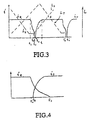
- Strand R (see Fig. 3) carries a constant, controlled current i.
- i In the power actuator to the switch T H and T R are closed. All other switches are open (Fig. 2).
- the current in the strand R is to be commutated and propagated in the strand S.
- the two switches T H and T R are opened.
- the current in the strand R flows back into the supply voltage source via the diodes D H and D R (see Fig. 2). Only at the time at which the current has become zero, ie has been completely commuted, the strand S may be energized. In Fig. 3, this time is designated t 2 .
- the Abkommut réellesvorgang must be completed before the strand S may be turned on.
- a premature switch-on (see Fig. 4) of the transistor T H, for example in conjunction with T S leads to a strong extension of the Abkommut réellesvorgangs, since then instead of the DC supply voltage only the forward voltage of the diode D H is available as an effective Abkommut réellesschreib.
- the Abkommut réellesvorgang lengthens, and it comes as a result to a generation of a significant braking torque. The overall yield of torque is reduced.
- the invention has for its object to reduce the cost of the power actuator as much as possible and optimize the control of the circuit breaker so that no burglaries in the time course of the Torque of the engine occur.
- the engine can be operated in a wide operating range despite the special topology of the power actuator without torque loss.
- the key to this is the premature closing of the switch T S before initiating the commutation process from the strand R to the strand S.
- the current control of the strand R provides an impression of the desired current by clocking the upper circuit breaker T H.
- a voltage time surface is applied to the strand, which just compensates in size just the effect of the inductance increase on the current amplitude.
- the same voltage time surface is now also supplied to the strand S, in which simply the switch T S is closed. That leads in the strand S to a continuous current build-up, since the inductance effective here is smaller than the inductance effective in the strand R and here the effect of an inductance increase is absent. If the desired current is reached in the strand S, the switch T S is shaded. If the transistor T H is turned on, the current goes through the diode D S and the switch T H in the freewheel (see Fig. 5).
- the Abkommut istsfast effective in the freewheeling mesh is only the sum of the forward voltage of said diode and that of the transistor T H. If the current in the strand S falls below its reference value, the switch T S is turned on again. This, of course, applies to everything, as well as the following, for every cyclic interchange of R, S and T.
- the switch T H and T R is opened in the described manner.
- the switch T S remains closed.
- the currents of both strands go into the freewheel, wherein the strand R abkommutiert via the diode D H and the diode D R against the full supply voltage and the strand S abkommutiert only against the forward voltage of the diode D H and the forward voltage of the switch T S.
- the detection of the time of commutation completion can be done with the following method, wherein the reverse voltages U R , U S and U T at the three lower workerschaltem T R , T S and T T used as information quantities (see Fig. 6).
- the strand R is commutated, its strand inductance at the switch T R imparts a blocking voltage in the amount of the DC supply voltage for the duration of the commutation process.
- a comparator is necessary here. This effort can be reduced to a single comparator K2.
- three low-power diodes D R , D S , D T are introduced (see Fig. 7).
- the anode of D R is connected to the anode of freewheeling diode D R and correspondingly the anodes of D S and D T to the anodes of D S die and D T.
- the cathodes of the three diodes D R , D S , D T are connected together and connected to ground with a high-impedance resistor. The voltage across this resistor is the desired test voltage U K2 .
- these three diodes represent a maximum value selector, ie the largest of the three voltages determines the magnitude of the output voltage.
Landscapes
- Engineering & Computer Science (AREA)
- Power Engineering (AREA)
- Control Of Motors That Do Not Use Commutators (AREA)
- Control Of Electric Motors In General (AREA)
Description
Der Motor dreht sich mit konstanter Änderungsgeschwindigkeit des Rotordrehwinkelsγ, also mit konstanter Drehzahl n.
Claims (5)
- Verfahren zum Ansteuern eines wechselrichtergespeisten Reluktanzmotors, mit Leistungsschaltern (TR, TS, TT )in den Zweigen niedrigen und hohen Potentials der Motorstränge, wobei im gemeinsamen Hochpotentialzweig nur ein Leistungsschalter (TH) vorgesehen ist, und mit Freilaufdioden (DH, DR, DS, DT), die die Stromanschlüsse niedrigen Potentials mit dem hohen Potential der Versorgungsspannung und den gemeinsamen Stranganschluß hohen Potentials mit dem Anschluß niedrigen Potentials der Versorgungsgleichspannung verbinden,
dadurch gekennzeichnet, daß vor dem Einleiten des Kommutierungsvorgangs eines ersten Strangs ( R,S,T) durch Öffnen des Leistungsschalters (TH) und Öffnen des Schalters (TR,TS,TT) im ersten Strang der Schalter (TS,TT,TR) des nächsten Strangs (S,T,R) geschlossen wird,
so daß bei Einleitung des Abkommutierungsvorgangs im ersten Strang (R,S,T) der nächste Strang (S,T,R) bereits voll bestromt ist, d.h., der Strom in diesem Strang einen Referenzwert erreicht hat, und daß für die Dauer der Kommutierung der Schalter im Hochpotentialzweig und der Schalter des ersten Strangs ausgeschaltet und der Schalter des nächsten Strangs eingeschaltet ist. - Verfahren nach Anspruch 1,
dadurch gekennzeichnet, daß dem nächsten Strang (S, R, T) vor der Abkommutierung des vorhergehenden Stranges (R, S, T) ein Sollwert vorgegeben wird, der um die Differenz des Stromes vor und nach der Abkommutierung erhöht ist. - Verfahren nach Anspruch 1 oder 2,
dadurch gekennzeichnet, daß durch Einstellung der Spannungszeitfläche der Strom im Strang konstant geregelt und die Wirkung des Induktivitätsanstiegs auf die Stromamplitude kompensiert wird. - Verfahren nach einem der Ansprüche 1 bis 3,
dadurch gekennzeichnet, daß die Spannungszeitfläche durch Takten des oberen Leistungsschalters TH eingestellt wird. - Verfahren nach einem der Ansprüche 1 bis 4,
dadurch gekennzeichnet, daß bei hochohmig überbrückten Schaltern (TR, TS, TT) im Niederpotentialzweig das Potential der zugehörigen Wicklungsanschlüsse überwacht wird, und auf das Ende der Kommutierung geschlossen wird, wenn das Potential aller zugehörigen Wicklungsanschlüsse näherungsweise das niedrigere Potential angenommen hat.
Applications Claiming Priority (2)
| Application Number | Priority Date | Filing Date | Title |
|---|---|---|---|
| DE4239668 | 1992-11-26 | ||
| DE4239668A DE4239668C1 (de) | 1992-11-26 | 1992-11-26 | Verfahren zum Ansteuern eines Reluktanzmotors |
Publications (4)
| Publication Number | Publication Date |
|---|---|
| EP0599334A2 EP0599334A2 (de) | 1994-06-01 |
| EP0599334A3 EP0599334A3 (de) | 1995-04-05 |
| EP0599334B1 EP0599334B1 (de) | 1997-04-02 |
| EP0599334B2 true EP0599334B2 (de) | 2003-07-02 |
Family
ID=6473645
Family Applications (1)
| Application Number | Title | Priority Date | Filing Date |
|---|---|---|---|
| EP93119063A Expired - Lifetime EP0599334B2 (de) | 1992-11-26 | 1993-11-25 | Verfahren zum Ansteuern eines Reluktanzmotors |
Country Status (3)
| Country | Link |
|---|---|
| EP (1) | EP0599334B2 (de) |
| DE (2) | DE4239668C1 (de) |
| ES (1) | ES2100429T5 (de) |
Families Citing this family (5)
| Publication number | Priority date | Publication date | Assignee | Title |
|---|---|---|---|---|
| DE4314211C2 (de) * | 1993-04-30 | 2000-06-21 | Daimler Chrysler Ag | Verfahren zur Steuerung des Abschaltvorgangs in den Strängen eines Reluktanzmotors |
| FR2744577B1 (fr) * | 1996-02-06 | 1998-04-24 | Moulinex Sa | Procede pour alimenter un moteur electrique a reluctance variable a commutation electronique, et circuit d'alimentation pour sa mise en oeuvre |
| DE19725629A1 (de) * | 1997-06-17 | 1999-02-04 | Aloys Wobben | Wechselrichter für die Einspeisung sinusförmiger Ströme in ein Wechselstromnetz |
| US6054819A (en) * | 1998-05-15 | 2000-04-25 | Tridelta Industries, Inc. | Driving circuit for switched reluctance machines |
| DE102005017658A1 (de) * | 2005-04-16 | 2007-01-25 | Aft Atlas Fahrzeugtechnik Gmbh | Steuereinrichtung zum Verstellen des Drehwinkels einer Nockenwelle |
Citations (1)
| Publication number | Priority date | Publication date | Assignee | Title |
|---|---|---|---|---|
| DE3940569A1 (de) † | 1989-12-08 | 1991-06-27 | Bosch Gmbh Robert | Schaltungsanordnung zum betreiben eines mehrphasen-synchronmotors an einem gleichspannungsnetz |
Family Cites Families (3)
| Publication number | Priority date | Publication date | Assignee | Title |
|---|---|---|---|---|
| DE3819097A1 (de) * | 1988-06-04 | 1989-12-14 | Philips Patentverwaltung | Schaltungsanordnung zum speisen eines reluktanzmotors |
| US5084662A (en) * | 1990-04-03 | 1992-01-28 | Sunstrand Corporation | Unipolar converter for variable reluctance machines |
| DE4029335A1 (de) * | 1990-09-15 | 1992-03-19 | Philips Patentverwaltung | Schaltungsanordnung zum kommutieren eines reluktanzmotors |
-
1992
- 1992-11-26 DE DE4239668A patent/DE4239668C1/de not_active Expired - Fee Related
-
1993
- 1993-11-25 DE DE59306022T patent/DE59306022D1/de not_active Expired - Fee Related
- 1993-11-25 ES ES93119063T patent/ES2100429T5/es not_active Expired - Lifetime
- 1993-11-25 EP EP93119063A patent/EP0599334B2/de not_active Expired - Lifetime
Patent Citations (1)
| Publication number | Priority date | Publication date | Assignee | Title |
|---|---|---|---|---|
| DE3940569A1 (de) † | 1989-12-08 | 1991-06-27 | Bosch Gmbh Robert | Schaltungsanordnung zum betreiben eines mehrphasen-synchronmotors an einem gleichspannungsnetz |
Non-Patent Citations (1)
| Title |
|---|
| IEEE Trans. on Industry Applications, Vol.25, Nr.13, 1989. Y.Murrai u.Tocque Ripple"Improvement for BrushlessDC Miniature Motors", pp 441,450. † |
Also Published As
| Publication number | Publication date |
|---|---|
| ES2100429T5 (es) | 2004-01-01 |
| EP0599334A2 (de) | 1994-06-01 |
| EP0599334B1 (de) | 1997-04-02 |
| ES2100429T3 (es) | 1997-06-16 |
| EP0599334A3 (de) | 1995-04-05 |
| DE59306022D1 (de) | 1997-05-07 |
| DE4239668C1 (de) | 1994-03-31 |
Similar Documents
| Publication | Publication Date | Title |
|---|---|---|
| DE69822896T2 (de) | Verfahren und gerät zur steuerung eines bürstenlosen elektrischen motors | |
| DE19846831B4 (de) | Verfahren und Vorrichtung zur Ermittlung der Rotorstellung von Synchronmotoren | |
| DE69410476T2 (de) | Pulsbreitenmodulierter motorregler | |
| EP1816739B1 (de) | Verfahren und Vorrichtung zur Regelung eines mehrphasigen, elektronisch kommutierten Motors | |
| DE69017152T2 (de) | Regelung eines bürstenlosen Motors mit mehreren Phasen und ohne Positionssensoren für den Rotor, unter Verwendung eines Systems der digitalen Filterung. | |
| DE19860446A1 (de) | Verfahren zur Regelung eines spannungs-/frequenzumrichtergesteuerten Mehrphasen-Permanentmagnetmotors | |
| DE10132837A1 (de) | Motor mit elektronischer Kommutierung | |
| DE3819062C2 (de) | ||
| EP2351203B1 (de) | Verfahren zum betreiben eines elektromotors | |
| DE3690376C2 (de) | ||
| DE3819064C3 (de) | Verfahren zur Steuerung von bürstenlosen Elektromotoren sowie Steuerschaltung hierfür | |
| DE3940569C2 (de) | ||
| EP1232561B1 (de) | Verfahren zum anfahren eines sensor- und bürstenlosen gleichstrommotors | |
| DE69420673T2 (de) | Bürstenloser elektrischer Motor und Verfahren zur Regelung des Motors | |
| EP0599334B2 (de) | Verfahren zum Ansteuern eines Reluktanzmotors | |
| EP3285381A1 (de) | Verfahren zum betreiben einer elektrischen maschine und elektrische maschine | |
| DE69206503T2 (de) | Hochgeschwindigkeits-gleichstrommotor. | |
| DE19815896C2 (de) | Drehzahl-Steuervorrichtung für einen elektronisch kommutierten mehrphasigen Elektromotor | |
| DE69736761T2 (de) | Regelvorrichtung für einen bürstenlosen Motor | |
| DE102004062580B4 (de) | Verfahren und Vorrichtung zur Regelung eines mehrphasigen, elektronisch kommutierten Motors | |
| DE3302209A1 (de) | Schrittmotor | |
| DE10163886A1 (de) | Verfahren zur elektronischen Kommutierung eines bürstenlosen Gleichstrommotors | |
| EP1228563B1 (de) | Elektronisch kommutierbarer motor | |
| EP0802613A2 (de) | Mehrphasiger, bürstenloser Gleichstrommotor | |
| DE69827592T2 (de) | Verfahren und Schaltungsvorrichtung zur Kommutation eines elektrischen Motors mit mehreren Windungen |
Legal Events
| Date | Code | Title | Description |
|---|---|---|---|
| PUAI | Public reference made under article 153(3) epc to a published international application that has entered the european phase |
Free format text: ORIGINAL CODE: 0009012 |
|
| AK | Designated contracting states |
Kind code of ref document: A2 Designated state(s): DE ES FR GB IT |
|
| 17P | Request for examination filed |
Effective date: 19941026 |
|
| PUAL | Search report despatched |
Free format text: ORIGINAL CODE: 0009013 |
|
| AK | Designated contracting states |
Kind code of ref document: A3 Designated state(s): DE ES FR GB IT |
|
| GRAG | Despatch of communication of intention to grant |
Free format text: ORIGINAL CODE: EPIDOS AGRA |
|
| 17Q | First examination report despatched |
Effective date: 19960425 |
|
| GRAH | Despatch of communication of intention to grant a patent |
Free format text: ORIGINAL CODE: EPIDOS IGRA |
|
| GRAH | Despatch of communication of intention to grant a patent |
Free format text: ORIGINAL CODE: EPIDOS IGRA |
|
| GRAA | (expected) grant |
Free format text: ORIGINAL CODE: 0009210 |
|
| AK | Designated contracting states |
Kind code of ref document: B1 Designated state(s): DE ES FR GB IT |
|
| ET | Fr: translation filed | ||
| REF | Corresponds to: |
Ref document number: 59306022 Country of ref document: DE Date of ref document: 19970507 |
|
| REG | Reference to a national code |
Ref country code: ES Ref legal event code: FG2A Ref document number: 2100429 Country of ref document: ES Kind code of ref document: T3 |
|
| GBT | Gb: translation of ep patent filed (gb section 77(6)(a)/1977) |
Effective date: 19970703 |
|
| PLBI | Opposition filed |
Free format text: ORIGINAL CODE: 0009260 |
|
| PLBF | Reply of patent proprietor to notice(s) of opposition |
Free format text: ORIGINAL CODE: EPIDOS OBSO |
|
| 26 | Opposition filed |
Opponent name: ROBERT BOSCH GMBH Effective date: 19971230 |
|
| PLBF | Reply of patent proprietor to notice(s) of opposition |
Free format text: ORIGINAL CODE: EPIDOS OBSO |
|
| RAP2 | Party data changed (patent owner data changed or rights of a patent transferred) |
Owner name: DAIMLERCHRYSLER AG |
|
| REG | Reference to a national code |
Ref country code: GB Ref legal event code: 732E |
|
| PLAW | Interlocutory decision in opposition |
Free format text: ORIGINAL CODE: EPIDOS IDOP |
|
| APAC | Appeal dossier modified |
Free format text: ORIGINAL CODE: EPIDOS NOAPO |
|
| APAE | Appeal reference modified |
Free format text: ORIGINAL CODE: EPIDOS REFNO |
|
| APAC | Appeal dossier modified |
Free format text: ORIGINAL CODE: EPIDOS NOAPO |
|
| APAC | Appeal dossier modified |
Free format text: ORIGINAL CODE: EPIDOS NOAPO |
|
| REG | Reference to a national code |
Ref country code: GB Ref legal event code: IF02 |
|
| APAC | Appeal dossier modified |
Free format text: ORIGINAL CODE: EPIDOS NOAPO |
|
| PLAW | Interlocutory decision in opposition |
Free format text: ORIGINAL CODE: EPIDOS IDOP |
|
| PUAH | Patent maintained in amended form |
Free format text: ORIGINAL CODE: 0009272 |
|
| STAA | Information on the status of an ep patent application or granted ep patent |
Free format text: STATUS: PATENT MAINTAINED AS AMENDED |
|
| 27A | Patent maintained in amended form |
Effective date: 20030702 |
|
| AK | Designated contracting states |
Designated state(s): DE ES FR GB IT |
|
| GBTA | Gb: translation of amended ep patent filed (gb section 77(6)(b)/1977) | ||
| REG | Reference to a national code |
Ref country code: ES Ref legal event code: DC2A Date of ref document: 20030711 Kind code of ref document: T5 |
|
| ET3 | Fr: translation filed ** decision concerning opposition | ||
| APAH | Appeal reference modified |
Free format text: ORIGINAL CODE: EPIDOSCREFNO |
|
| PGFP | Annual fee paid to national office [announced via postgrant information from national office to epo] |
Ref country code: FR Payment date: 20051110 Year of fee payment: 13 Ref country code: DE Payment date: 20051110 Year of fee payment: 13 |
|
| PGFP | Annual fee paid to national office [announced via postgrant information from national office to epo] |
Ref country code: GB Payment date: 20051121 Year of fee payment: 13 Ref country code: ES Payment date: 20051121 Year of fee payment: 13 |
|
| PGFP | Annual fee paid to national office [announced via postgrant information from national office to epo] |
Ref country code: IT Payment date: 20061130 Year of fee payment: 14 |
|
| PG25 | Lapsed in a contracting state [announced via postgrant information from national office to epo] |
Ref country code: DE Free format text: LAPSE BECAUSE OF NON-PAYMENT OF DUE FEES Effective date: 20070601 |
|
| GBPC | Gb: european patent ceased through non-payment of renewal fee |
Effective date: 20061125 |
|
| REG | Reference to a national code |
Ref country code: FR Ref legal event code: ST Effective date: 20070731 |
|
| PG25 | Lapsed in a contracting state [announced via postgrant information from national office to epo] |
Ref country code: GB Free format text: LAPSE BECAUSE OF NON-PAYMENT OF DUE FEES Effective date: 20061125 |
|
| REG | Reference to a national code |
Ref country code: ES Ref legal event code: FD2A Effective date: 20061127 |
|
| PG25 | Lapsed in a contracting state [announced via postgrant information from national office to epo] |
Ref country code: FR Free format text: LAPSE BECAUSE OF NON-PAYMENT OF DUE FEES Effective date: 20061130 Ref country code: ES Free format text: LAPSE BECAUSE OF NON-PAYMENT OF DUE FEES Effective date: 20061127 |
|
| PG25 | Lapsed in a contracting state [announced via postgrant information from national office to epo] |
Ref country code: IT Free format text: LAPSE BECAUSE OF NON-PAYMENT OF DUE FEES Effective date: 20071125 |