EP0597938B1 - Verfahren und vorrichtung zum brechen des bandes eines ballens - Google Patents
Verfahren und vorrichtung zum brechen des bandes eines ballens Download PDFInfo
- Publication number
- EP0597938B1 EP0597938B1 EP92916465A EP92916465A EP0597938B1 EP 0597938 B1 EP0597938 B1 EP 0597938B1 EP 92916465 A EP92916465 A EP 92916465A EP 92916465 A EP92916465 A EP 92916465A EP 0597938 B1 EP0597938 B1 EP 0597938B1
- Authority
- EP
- European Patent Office
- Prior art keywords
- band
- mandrel
- bale
- blade
- debanding
- Prior art date
- Legal status (The legal status is an assumption and is not a legal conclusion. Google has not performed a legal analysis and makes no representation as to the accuracy of the status listed.)
- Expired - Lifetime
Links
Images


Classifications
-
- B—PERFORMING OPERATIONS; TRANSPORTING
- B26—HAND CUTTING TOOLS; CUTTING; SEVERING
- B26F—PERFORATING; PUNCHING; CUTTING-OUT; STAMPING-OUT; SEVERING BY MEANS OTHER THAN CUTTING
- B26F3/00—Severing by means other than cutting; Apparatus therefor
- B26F3/02—Tearing
-
- B—PERFORMING OPERATIONS; TRANSPORTING
- B65—CONVEYING; PACKING; STORING; HANDLING THIN OR FILAMENTARY MATERIAL
- B65B—MACHINES, APPARATUS OR DEVICES FOR, OR METHODS OF, PACKAGING ARTICLES OR MATERIALS; UNPACKING
- B65B69/00—Unpacking of articles or materials, not otherwise provided for
- B65B69/0025—Removing or cutting binding material, e.g. straps or bands
-
- Y—GENERAL TAGGING OF NEW TECHNOLOGICAL DEVELOPMENTS; GENERAL TAGGING OF CROSS-SECTIONAL TECHNOLOGIES SPANNING OVER SEVERAL SECTIONS OF THE IPC; TECHNICAL SUBJECTS COVERED BY FORMER USPC CROSS-REFERENCE ART COLLECTIONS [XRACs] AND DIGESTS
- Y10—TECHNICAL SUBJECTS COVERED BY FORMER USPC
- Y10S—TECHNICAL SUBJECTS COVERED BY FORMER USPC CROSS-REFERENCE ART COLLECTIONS [XRACs] AND DIGESTS
- Y10S83/00—Cutting
- Y10S83/909—Cutting strand extending from or lying on strand or package support
-
- Y—GENERAL TAGGING OF NEW TECHNOLOGICAL DEVELOPMENTS; GENERAL TAGGING OF CROSS-SECTIONAL TECHNOLOGIES SPANNING OVER SEVERAL SECTIONS OF THE IPC; TECHNICAL SUBJECTS COVERED BY FORMER USPC CROSS-REFERENCE ART COLLECTIONS [XRACs] AND DIGESTS
- Y10—TECHNICAL SUBJECTS COVERED BY FORMER USPC
- Y10T—TECHNICAL SUBJECTS COVERED BY FORMER US CLASSIFICATION
- Y10T225/00—Severing by tearing or breaking
- Y10T225/10—Methods
-
- Y—GENERAL TAGGING OF NEW TECHNOLOGICAL DEVELOPMENTS; GENERAL TAGGING OF CROSS-SECTIONAL TECHNOLOGIES SPANNING OVER SEVERAL SECTIONS OF THE IPC; TECHNICAL SUBJECTS COVERED BY FORMER USPC CROSS-REFERENCE ART COLLECTIONS [XRACs] AND DIGESTS
- Y10—TECHNICAL SUBJECTS COVERED BY FORMER USPC
- Y10T—TECHNICAL SUBJECTS COVERED BY FORMER US CLASSIFICATION
- Y10T225/00—Severing by tearing or breaking
- Y10T225/30—Breaking or tearing apparatus
-
- Y—GENERAL TAGGING OF NEW TECHNOLOGICAL DEVELOPMENTS; GENERAL TAGGING OF CROSS-SECTIONAL TECHNOLOGIES SPANNING OVER SEVERAL SECTIONS OF THE IPC; TECHNICAL SUBJECTS COVERED BY FORMER USPC CROSS-REFERENCE ART COLLECTIONS [XRACs] AND DIGESTS
- Y10—TECHNICAL SUBJECTS COVERED BY FORMER USPC
- Y10T—TECHNICAL SUBJECTS COVERED BY FORMER US CLASSIFICATION
- Y10T29/00—Metal working
- Y10T29/49—Method of mechanical manufacture
- Y10T29/49815—Disassembling
- Y10T29/49821—Disassembling by altering or destroying work part or connector
-
- Y—GENERAL TAGGING OF NEW TECHNOLOGICAL DEVELOPMENTS; GENERAL TAGGING OF CROSS-SECTIONAL TECHNOLOGIES SPANNING OVER SEVERAL SECTIONS OF THE IPC; TECHNICAL SUBJECTS COVERED BY FORMER USPC CROSS-REFERENCE ART COLLECTIONS [XRACs] AND DIGESTS
- Y10—TECHNICAL SUBJECTS COVERED BY FORMER USPC
- Y10T—TECHNICAL SUBJECTS COVERED BY FORMER US CLASSIFICATION
- Y10T29/00—Metal working
- Y10T29/51—Plural diverse manufacturing apparatus including means for metal shaping or assembling
- Y10T29/5136—Separate tool stations for selective or successive operation on work
- Y10T29/5137—Separate tool stations for selective or successive operation on work including assembling or disassembling station
- Y10T29/5139—Separate tool stations for selective or successive operation on work including assembling or disassembling station and means to sever work prior to disassembling
-
- Y—GENERAL TAGGING OF NEW TECHNOLOGICAL DEVELOPMENTS; GENERAL TAGGING OF CROSS-SECTIONAL TECHNOLOGIES SPANNING OVER SEVERAL SECTIONS OF THE IPC; TECHNICAL SUBJECTS COVERED BY FORMER USPC CROSS-REFERENCE ART COLLECTIONS [XRACs] AND DIGESTS
- Y10—TECHNICAL SUBJECTS COVERED BY FORMER USPC
- Y10T—TECHNICAL SUBJECTS COVERED BY FORMER US CLASSIFICATION
- Y10T83/00—Cutting
- Y10T83/929—Tool or tool with support
- Y10T83/9319—Toothed blade or tooth therefor
Definitions
- the present invention relates to a bale debanding device for breaking bands holding a bale together. More particularly, the invention relates to a device for severing the banding material holding a bale of used paper products together, removing and coiling the material, and depositing it into a collection bin.
- Certain types of re-pulping machinery require that the banding material holding a bale of used paper products together be removed before processing begins.
- the banding material usually metal wire or bands
- the banding material must be cut and removed from the bales before the paper product can enter the re-pulper. Because the re-pulping machinery is sensitive to the introduction of such banding material, it will generally break down or become contaminated if any non-wood fiber material is introduced therein.
- US2820282 discloses a bale debanding device as set out in the precharacterising portion of claim 1.
- the band cutter is simply a rotary blade without any notches or teeth, and the bales will accordingly be damaged when the bands around them are cut.
- bale debanding device as set out in claim 1.
- the band breaking blade has at least one notch or removed material section to cause the banding material to engage the blade when it is brought in contact therewith. Once engaged, the banding material is brought to bear on the anvil whereupon each side of the anvil supports the banding material and the band breaking blade causes a point load substantially in the middle and perpendicular to the material. Because the band breaking blade is rotating, the force exerted by it on the banding material continues until it exceeds the banding material's sheer point, at which time the banding material breaks.
- a preferred feature of the present invention provides for a flexible pressure slap assembly to aid in the wrapping of removed banding material. This assembly is positioned so that banding material encircling the mandrel will be urged to remain thereon.
- Another preferred feature of the present invention provides for a pivoted protective hood to substantially enclose the band removing assembly.
- This assembly is positioned in a similar manner as the pressure flap assembly.
- the protective hood substantially encloses the upper portion of the mandrel, thereby preventing the removed and rotating banding material from extending much beyond the area of the mandrel.
- the protective hood can be pivoted away from the mandrel to permit removal of the coiled banding material.
- Still another preferred feature of the present invention provides for a movable cleaning assembly to remove banding material coiled on the mandrel.
- Attached to the vertical support member is a cleaning plate support member that is mounted in substantially the same plane as defined by the mandrel and vertical support.
- Located on the cleaning support member is an axially movable cleaning plate having a lower portion constructed so as to closely fit the upper arc portion of the mandrel.
- both the band breaking blade and the anvil may be constructed of hardened steel so as to resist the destructive forces encountered when breaking high tensile strength banding material such as wire.
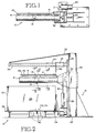
- a debanding device 12 is shown to have frame 14 with vertical support member 22 and horizontal support member 24.
- Horizontal support member 24 supports bale receiving table 26 through which band breaking blade 42 passes.
- Vertical support member 22 provides support for mandrel support member 32 and cleaning plate support member 34.
- mandrel 16 is rotatably located in mandrel collar 77 and supported therein by bearings 76 which are preferably high load type bearings.
- Mandrel collar 77 is fixedly attached to mandrel support member 32 which is in turn slidably mounted to vertical support member 22 so as to permit vertical movement thereon by means of hydraulic cylinder 38 and piston rod 50.
- Mandrel 16 is caused to rotate by hydraulic motor 20 and drive chain 21 rotating sprocket 78.
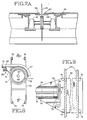
- cleaning plate support member 34 is attached to vertical frame 22 at a location above mandrel support member 32. To reduce the torque moment acting on the attachment point, cleaning plate support member 34 is further supported by brace 33. Cleaning plate 36 is mounted for reciprocating axial motion along cleaning plate support member 34. Cleaning plate 36 is driven by motor 35 and chain 40. In preferred form, cleaning plate 36 includes sliding collar 37 which is in sliding engagement with cleaning plate support member 34. Those persons skilled in the art will recognize that numerous possibilities exist for providing a bearing-type sliding engagement between sliding collar 37 and cleaning plate support member 34. As shown in Fig. 3, cleaning plate 36 is preferably constructed to have two portions: a first portion 52 is an ultra-high molecular weight plastic while a second portion 53 is a mild steel plate that is attached to collar 37.
- pressure flap assembly 39 includes a pair of flexible pressure flaps 41 and frame member 45 which is attached to mandrel support member 32.
- Flexible pressure flaps 41 preferably constructed of thick reinforced rubber, contact mandrel 16 in such a manner so as to aid in holding banding material 30 in place on rotating mandrel 16.
- Frame member 45 is adjustable such that the pressure applied by flexible pressure flaps 41 against mandrel 16 can be varied by repositioning frame member 45.
- Typical flexible pressure flap 41 engagement with mandrel 16 is shown in Fig. 8.
- protective hood 47 which is pivotally attached thereto by hinge 51.
- Protective hood 47 fits closely over mandrel 16, aiding in the wrapping or winding of banding material 30 around mandrel 16.
- plastic end plates may be added to the ends of protective hood 47 to further aid the winding process of banding material 30 and increase safety for persons near debanding device 12.
- Protective hood 47 pivots on frame member 45 in order to swing out of the way of cleaning plate 36 during the banding material removal process.
- Band breaking blade 42 is mounted for rotatable motion on horizontal frame 24 using a pair of bearing blocks 43 (see Fig. 2a). As shown in Fig. 2a, band breaking blade 42 is positioned to rotate through anvil 49 which is made of a hardened steel, e.g., ASTRALOY® , which aids in the breaking of banding material 30, as is further described below.
- anvil 49 which is made of a hardened steel, e.g., ASTRALOY® , which aids in the breaking of banding material 30, as is further described below.
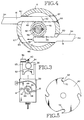
- Mandrel 16 includes hollow portion 44 wherein pinion shaft 56 and pinion gear 46 are located. Pinion shaft 56 drives pinion gear 46 which in turn drives band catches 18 to retract or extend by engaging a rack portion 48 of band catches 18 (as shown in Fig. 4).
- each band catch 18 includes protruding portion 54 and rack portion 48.
- Rack portion 48 of each band catch 18 is in meshing engagement with pinion gear 46.
- Pinion gear 46 is driven by axially aligned pinion shaft 56 through key member 58.
- Each band catch 18 extends through a machined opening 60. Openings 60 extend generally radially to mandrel 16, however these openings are spaced sufficiently off-center to allow pinion gear 46 to be placed between the pair of rack portions 48.
- band catches 18 and pinion gear 46 are carried by band catch disk 61, as shown in Fig. 11.
- Each band catch 18 includes rack end 62 and outer end 64.
- Mandrel 16 includes cavity 66 for receiving rack end 62 of band catch 18 when it is in its retracted position. Cover plate 67 covers cavity 66.
- Band catch disk 61 described above is preferably machined from a solid disk of steel. As best shown in Fig. 11, band catch disk 61 performs two functions. First, it provides a way to join the two segments of mandrel 16 together. Second, and more importantly, band catch disk 61 houses band catches 18 by having openings 60 through which band catches 18 reciprocate. Hydraulic rotary actuator 72 is mounted to band catch disk 61 so that pinion shaft 56 extends therein. When subject to a hydraulic pressure, hydraulic rotary actuator 72 causes pinion shaft 56 and pinion gear 46 to rotate, thereby causing band catches 18 to extend or retract.
- band breaking blade 42 is shown.
- Band breaking blade 42 is preferably constructed from a 22.7 cm ASTRALOY® blade that has been machined and heat treated to approximately 815° C and air cooled.
- band breaking blade 42 has uniform notches 68 removed from it. Each notch has an internal diameter of approximately 3.5 cm.
- Internal edge 70 is preferably sharpened to aid in breaking banding material 30.
- the circumferential edge of band breaking blade 42 is tapered as indicated in Fig. 6 at A to 30 degrees from sectional center before being heat-treated.
- Anvil inserts 49 aid band breaking blade 42 in breaking banding material 30 by providing side supports to limit banding material 30 from distributing the force created by band breaking blade 42 beyond a narrow length of material bounded by each edge of anvil inserts 49.
- the sequential action of band breaking blade 42 on a length of banding material 30 is best shown in Figs. 12-14.
- the combination of notches 68 in conjunction with anvil inserts 49 provide a most efficient use of energy for breaking banding material 30.
- use of anvil inserts 49 localizes the point of breakage, thereby ensuring that band catches 18 will engage a sufficient length of banding material 30 so that it may be effectively removed from bale 28.
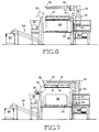
- Support table 26 is slidable on plastic strips or any other low friction surface so that bale 28 can be moved progressively under mandrel 16 by a drive system.
- mandrel 16 Upon activation of the apparatus, mandrel 16 is rotated by drive motor 20 and drive chain 21, at a preferred rate of 18 rpm and band catches 18 are moved to their extended position by pressurizing hydraulic rotary actuator 72.
- Hydraulic rotary actuator 72 cause pinion shaft 56 to rotate until the applied hydraulic pressure is stopped, at which point pinion shaft 56 is locked in place, holding it stationary relative to mandrel 16.
- Supplying hydraulic rotary actuator 72 with fluid are two hydraulic hoses which pass through rotating union 80 at the driven end of mandrel 16. After band catches 18 have attained their extended position, mandrel 16 is lowered by hydraulic cylinder 38 and piston rod 50 to a position adjacent bale 28.
- band breaking blade 42 is rotated by a hydraulic motor and chain (not shown) at a rate below 100 rpm and preferably at 4 to 10 rpm.
- the direction of rotation is preferably toward the approaching bale so as to pull down on banding material when engaged by a notch 68.
- banding material 30 is caused to contact both portions of anvil inserts 49 as best illustrated in Fig. 13.
- the resulting force from the inherent torque of band breaking blade 42 in a direction perpendicular to table 26 in combination with sharp edge 70 cause banding material 30 to break (See Fig. 14).
- banding material 30 breaks, it engages one of the band catches 18. Consequently, banding material 30 begins to wrap around mandrel 16 since it is engaged with band catch 18 and held thereto by flexible pressure flap 41 and protective hood 47.
- Mandrel 16 is preferably rotated so that band catch 18 makes a climbing cut, i.e., rotated toward and downwardly into the approaching bale 28.
- Bale 28 continues to move through the apparatus until all banding materials 30 are removed from one surface of bale 28. Depending upon the type of bale 28 and number of bands 30 broken, it may be desired to remove the accumulating bands from mandrel 16. If this is desired, protective hood 47 is caused to pivot away from mandrel 16, thereby exposing the top portion of mandrel 16 to facilitate the removal of banding material 30.
- mandrel 16 is preferably extended to a position above the bale by hydraulic cylinder 38 and piston rod 50 so that cleaning blade 36 is adjacent mandrel 16.
- Hydraulic pressure to hydraulic rotary actuator 72 is reversed so that the closed centered valves reverse the direction of rotation of pinion shaft 56 which in turn rotates pinion gear 46, thereby retracting band catches 18 into hollow portion 44 of mandrel 16.
- cleaning plate 36 is drawn toward the free end of mandrel 16 to remove the coiled banding material 30 into receiver 90 which may then deliver the banding material 30 to chopper 92 via conveyor 94.
- Mandrel 16 may continue to rotate during this step or may be stopped. Cleaning plate 36 is then returned to its initial position and the process is repeated.
- bale 28 may either be repositioned and moved through the debanding apparatus as described above, or a second debanding apparatus may be used wherein the mandrel 16 and the band breaking blade 42 are each mounted to a linear actuator capable of moving mandrel 16 and band breaking blade 42 over a different surface of bale 28, until all of the bands 30 have been removed from bale 28.
- bale 28 may be positioned such that the direction of movement across table 26 is diagonal to plane of rotation of band breaking blade 42. In this fashion, only one pass through the apparatus may be needed for a bale having any number of perpendicularly intersecting bands.
- the present invention will find applicability and industrial utility in industries that handle and process baled materials. More particularly, the invention can be used in the wood fiber recycling industry where removal of banding material from bales is desired.
Landscapes
- Engineering & Computer Science (AREA)
- Mechanical Engineering (AREA)
- Life Sciences & Earth Sciences (AREA)
- Forests & Forestry (AREA)
- Control And Other Processes For Unpacking Of Materials (AREA)
Claims (7)
- Ballenbandablösevorrichtung (12) zum Brechen von Bändern (30), die einen Ballen (28) zusammenhalten, gekennzeichnet durch:eine Bandbrechklinge (42), wobei die Klinge mindestens eine Bandrückhaltekerbe (68) aufweist, die in einem Randbereich der Klinge ausgebildet ist, wobei die Rückhaltekerbe (68) so gestaltet ist, daß sie ein Band (30) erfaßt und festhält, wenn die Klinge gedreht wird, und das Band im allgemeinen senkrecht zur Klinge bewegt wird; undeinen Amboß (49), der in unmittelbarer Nähe der Klinge (42) angeordnet ist und einen Schlitz aufweist, um den Durchtritt der Klinge zu gestatten, um die Klinge beim Brechen des Bandes durch Einschränkung und örtliche Begrenzung der Dehnung des Bandes wahrend der Einwirkung der Klinge auf das Band zu unterstützen.
- Bandablösevorrichtung nach Anspruch 1, die ferner dafür vorgesehen ist, Bänder von einem Ballen (28) zu entfernen, umfassend:einen axial drehbaren Dorn (16), der von einer vertikalen Stütze (22) getragen wird, wobei der Dorn (16) einen Innenbereich (44) und eine äußere Oberfläche und mindestens eine Bandfängeröffnung (60) aufweist, die sich von dem Innenbereich bis zur äußeren Oberfläche erstreckt;mindestens einen ausfahrbaren Bandfänger (18) mit einer eingezogenen Position innerhalb des Innenbereichs und einer ausgefahrenen Position, wobei der Bandfänger (18) einen Bandergreifungsteil (64), der sich im allgemeinen von der äußeren Oberfläche des Dorns (16) radial nach außen erstreckt, wenn er sich in der ausgefahrenen Position befindet, und einen Zahnstangenteil (62) aufweist, der sich im Innenbereich des Dorns hin- und herbewegt; undein unabhängig drehbares Zahnrad (46) in Zahneingriff mit dem Zahnstangenteil (48), wobei das Zahnrad das Ausfahren und Einziehen des mindestens einen Bandfängers (18) unabhängig von der Drehung des Dorns (16) steuert.
- Bandablösevorrichtung nach Anspruch 2, bei der ein Antriebsmotor (20) den Dorn (16) dreht und ein Drehantriebsorgan (72) das Zahnrad dreht und auf diese Weise das Ausfahren und Einziehen des mindestens einen Bandfängers (18) steuert.
- Bandablösevorrichtung nach Anspruch 2 oder Anspruch 3, bei der eine Druckklappenanordnung (39), die mindestens eine flexible Druckklappe (41) umfaßt, so positioniert ist, daß die mindestens eine Klappe (41) in bandergreifendem Kontakt mit dem Dorn (16) ist.
- Bandablösevorrichtung nach einem der Ansprüche 2, 3 oder 4, bei der eine Putzplatte (36) so gestaltet ist, daß sie um einen Bereich des Dorns enganliegend paßt, und die Platte (36) für eine axiale Bewegung entlang des Dorns montiert ist, wobei die Platte axial angetrieben wird, um die Bänder von dem Dorn zu entfernen.
- Bandablösevorrichtung nach einem der vorhergehenden Ansprüche, die außerdem einen Ballenaufnahmetisch (26) umfaßt, wobei der Tisch eine im allgemeinen ebene Aufnahmefläche und eine Stützkonstruktion aufweist.
- Bandablösevorrichtung nach einem der vorhergehenden Ansprüche, die außerdem einen Motor umfaßt, der funktionell mit der Bandbrechklinge (42) verbunden ist, um diese in Drehung zu versetzen.
Applications Claiming Priority (3)
| Application Number | Priority Date | Filing Date | Title |
|---|---|---|---|
| US07/731,430 US5216797A (en) | 1991-07-17 | 1991-07-17 | Method and apparatus for debanding a bale |
| US731430 | 1991-07-17 | ||
| PCT/US1992/005862 WO1993001911A1 (en) | 1991-07-17 | 1992-07-17 | Method and apparatus for debanding a bale |
Publications (3)
| Publication Number | Publication Date |
|---|---|
| EP0597938A1 EP0597938A1 (de) | 1994-05-25 |
| EP0597938A4 EP0597938A4 (de) | 1994-12-28 |
| EP0597938B1 true EP0597938B1 (de) | 1997-10-08 |
Family
ID=24939479
Family Applications (1)
| Application Number | Title | Priority Date | Filing Date |
|---|---|---|---|
| EP92916465A Expired - Lifetime EP0597938B1 (de) | 1991-07-17 | 1992-07-17 | Verfahren und vorrichtung zum brechen des bandes eines ballens |
Country Status (6)
| Country | Link |
|---|---|
| US (2) | US5216797A (de) |
| EP (1) | EP0597938B1 (de) |
| JP (1) | JPH06509286A (de) |
| CA (1) | CA2113180C (de) |
| DE (1) | DE69222648D1 (de) |
| WO (1) | WO1993001911A1 (de) |
Families Citing this family (19)
| Publication number | Priority date | Publication date | Assignee | Title |
|---|---|---|---|---|
| US5216797A (en) * | 1991-07-17 | 1993-06-08 | R. Hall Manufacturing Inc. | Method and apparatus for debanding a bale |
| EP0745537B1 (de) * | 1995-06-02 | 1998-07-15 | Lamb-Grays Harbor Co. | Verfahren und Vorrichtung zum Entfernen von Drähten von Ballen aus kompressiblem Material |
| DE19520248A1 (de) * | 1995-06-02 | 1996-12-05 | Truetzschler Gmbh & Co Kg | Verfahren und Vorrichtung zur Trennung von Umreifungen, z. B. Drähte, Bänder, Bandagen und/oder Verpackung (Emballage) von Textilfaserballen |
| DE19520247A1 (de) * | 1995-06-02 | 1996-12-05 | Truetzschler Gmbh & Co Kg | Vorrichtung zur Ermittlung von metallischen Umreifungen, wie Drähte, Bänder o. dgl. für Textilfaserballen |
| NL1000912C1 (nl) * | 1995-08-01 | 1997-02-04 | Haanschoten Josef Gijsbert | Snel draaiende handcirkelzaag en zaagschijf daarvoor. |
| US5811829A (en) † | 1995-08-10 | 1998-09-22 | Arco Chemical Technology, L.P. | Viscosity stable isocyanate-terminated prepolymers and polyoxyalkylene polyether polyols having improved storage stability |
| US5664585A (en) * | 1996-09-10 | 1997-09-09 | Mactavish Machine Manufacturing Co. | Apparatus for cutting tie elements of hands of tobacco |
| US6115904A (en) * | 1997-10-31 | 2000-09-12 | Lamb-Grays Harbor Co. | Rotatable dewiring apparatus and method |
| US6986233B1 (en) * | 2004-08-31 | 2006-01-17 | Illinois Tool Works, Inc. | Bale dewiring system |
| US20060191241A1 (en) * | 2005-02-28 | 2006-08-31 | Deutsch Timothy A | Module wrap removal |
| US20070044603A1 (en) * | 2005-08-24 | 2007-03-01 | Scholtes William J | Automated de-strapper |
| WO2008052175A1 (en) * | 2006-10-27 | 2008-05-02 | Busse/Sji Corporation | Strap removal system |
| AU2008227052A1 (en) * | 2008-09-25 | 2010-04-08 | Visy R & D Pty Ltd | Multifunction tool for depalletising |
| EP2729376A4 (de) * | 2011-06-30 | 2015-05-20 | Mark Gerlinger Lyman | Verarbeitungsanlage für biomasseballen mit automatischem bindungsentferner |
| ES2424567B2 (es) * | 2013-03-27 | 2014-04-03 | Guerrero Montes Ingeniería, S.L. | Sistema recogedor de cuerdas de fardos |
| FI125241B (en) * | 2013-12-23 | 2015-07-31 | Cross Wrap Oy | Device for opening a bale |
| CN108637562B (zh) * | 2018-05-22 | 2020-03-24 | 嵊州市恒中机器有限公司 | 矫正式车头后靠档焊装用定位工装 |
| CN111842540B (zh) * | 2020-07-20 | 2022-07-26 | 湖南森钢新材料科技股份有限公司 | 一种钢卷卷曲机的钢卷支撑固定结构 |
| CN114044223B (zh) * | 2021-10-29 | 2023-04-04 | 山鹰国际控股股份公司 | 一种用于纸包断丝的液压断丝初散装置 |
Family Cites Families (21)
| Publication number | Priority date | Publication date | Assignee | Title |
|---|---|---|---|---|
| US1076920A (en) * | 1912-08-13 | 1913-10-28 | Harry M Sprecher | Winding-machine. |
| US1291669A (en) * | 1917-02-28 | 1919-01-14 | Bridgeport Brass Co | Coiling apparatus. |
| US1859051A (en) * | 1930-04-26 | 1932-05-17 | Richter Alfred | Curtain wrapping machine |
| US1956429A (en) * | 1932-03-02 | 1934-04-24 | Firestone Tire & Rubber Co | Slitting machine |
| US1998893A (en) * | 1932-09-28 | 1935-04-23 | Charles B Cole | Boring and facing tool head |
| US2820282A (en) * | 1954-08-06 | 1958-01-21 | Jack B Tropp | Apparatus for removing ties from packages |
| US2839258A (en) * | 1955-11-02 | 1958-06-17 | Delbert G Jacobson | Wire winding spool mechanism |
| US2992592A (en) * | 1956-10-18 | 1961-07-18 | Agfa Ag | Masking frame for making enlargements |
| US2941743A (en) * | 1958-07-31 | 1960-06-21 | United States Steel Corp | Wire fabric reeling mandrel with rotatably retractable winding hooks |
| US3006565A (en) * | 1960-06-30 | 1961-10-31 | Eugene V Pelletier | Bobbin clutch |
| US3281092A (en) * | 1961-08-17 | 1966-10-25 | Schultz Sales Corp | Self-adjusting mill roll supporting mandrel |
| US3279010A (en) * | 1965-06-28 | 1966-10-18 | Peter A Misanchuk | Cord-length varying device |
| US3513522A (en) * | 1967-04-03 | 1970-05-26 | Victor J Thomson | Unbaling machine |
| SE390918B (sv) * | 1973-11-28 | 1977-01-31 | Stridsberg & Bjorck Ab | Bulleravstord cirkelsagklinga |
| DE2821336C2 (de) * | 1978-05-16 | 1980-07-31 | B+G-Foerdertechnik Gmbh, 5350 Euskirchen | Wickelkopf |
| US4270428A (en) * | 1979-07-25 | 1981-06-02 | Black & Decker Inc. | Kerf guide and cautionary marker for a power driven tool |
| DE3229765A1 (de) * | 1982-08-10 | 1984-02-16 | GAO Gesellschaft für Automation und Organisation mbH, 8000 München | Vorrichtung zum entfernen einer banderole von einem blattbuendel |
| US4871619A (en) * | 1983-11-30 | 1989-10-03 | International Business Machines Corporation | Electronic components comprising polymide dielectric layers |
| JPH03111236A (ja) * | 1989-09-19 | 1991-05-13 | Tateno Kikai Seisakusho:Kk | 包装枚葉紙の開封処理方法 |
| US5079826A (en) * | 1990-05-15 | 1992-01-14 | Lamb-Grays Harbor Co. | Wire cutting and removal apparatus |
| US5216797A (en) * | 1991-07-17 | 1993-06-08 | R. Hall Manufacturing Inc. | Method and apparatus for debanding a bale |
-
1991
- 1991-07-17 US US07/731,430 patent/US5216797A/en not_active Expired - Lifetime
-
1992
- 1992-07-17 CA CA002113180A patent/CA2113180C/en not_active Expired - Fee Related
- 1992-07-17 JP JP5502896A patent/JPH06509286A/ja active Pending
- 1992-07-17 DE DE69222648T patent/DE69222648D1/de not_active Expired - Lifetime
- 1992-07-17 EP EP92916465A patent/EP0597938B1/de not_active Expired - Lifetime
- 1992-07-17 WO PCT/US1992/005862 patent/WO1993001911A1/en not_active Ceased
-
1993
- 1993-06-03 US US08/071,459 patent/US5400493A/en not_active Expired - Lifetime
Also Published As
| Publication number | Publication date |
|---|---|
| CA2113180C (en) | 1999-01-05 |
| WO1993001911A1 (en) | 1993-02-04 |
| US5400493A (en) | 1995-03-28 |
| JPH06509286A (ja) | 1994-10-20 |
| DE69222648D1 (de) | 1997-11-13 |
| EP0597938A1 (de) | 1994-05-25 |
| EP0597938A4 (de) | 1994-12-28 |
| CA2113180A1 (en) | 1993-02-04 |
| US5216797A (en) | 1993-06-08 |
Similar Documents
| Publication | Publication Date | Title |
|---|---|---|
| EP0597938B1 (de) | Verfahren und vorrichtung zum brechen des bandes eines ballens | |
| US4929141A (en) | Bale-opening method and apparatus | |
| US4104792A (en) | Wheel and tire cutter | |
| US8707532B2 (en) | Method for removing wires from a bale | |
| DE3239178C2 (de) | ||
| DE19650943B4 (de) | Maschine zum Auspacken eines Ballens, insbesondere eines Tabakballens, aus einer Verpackung | |
| CN113800290A (zh) | 一种薄膜包装装置及薄膜收卷包装一体化设备 | |
| EP2121453A1 (de) | Ballenzange zum anschluss an eine arbeitsmaschine | |
| US11458646B2 (en) | Method and apparatus for removing wrapping from rolls | |
| US5024386A (en) | Tire converting apparatus and method | |
| GB2033816A (en) | Bale cutting apparatus and methods | |
| US6305277B1 (en) | Coil handling device | |
| US4922976A (en) | Apparatus for removing branches from and for crosscutting treetrunks | |
| US5199337A (en) | Tire cutter apparatus | |
| US4802635A (en) | Apparatus and method for compacting a scrap tire | |
| US4205573A (en) | Method and apparatus for automatically cutting long rolls of microfoam material and the like into shorter sub-rolls | |
| CN213737882U (zh) | 一种便于清理边角料的胶带分切机 | |
| US4729272A (en) | Wire rope salvaging apparatus | |
| CN110834774A (zh) | 一种便携式打包带剪切装置 | |
| CN222860820U (zh) | 一种预置打包带的边丝机 | |
| CN222988576U (zh) | 一种管料拆捆装置 | |
| CN219750801U (zh) | 一种钢管自动上、送料系统 | |
| US5584215A (en) | Tire cutting apparatus | |
| CN219905021U (zh) | 一种自动割袋挡板机构 | |
| CN223850920U (zh) | 残卷打包机及残卷打包系统 |
Legal Events
| Date | Code | Title | Description |
|---|---|---|---|
| PUAI | Public reference made under article 153(3) epc to a published international application that has entered the european phase |
Free format text: ORIGINAL CODE: 0009012 |
|
| 17P | Request for examination filed |
Effective date: 19940217 |
|
| AK | Designated contracting states |
Kind code of ref document: A1 Designated state(s): DE FR GB IT |
|
| A4 | Supplementary search report drawn up and despatched |
Effective date: 19941108 |
|
| AK | Designated contracting states |
Kind code of ref document: A4 Designated state(s): DE FR GB IT |
|
| 17Q | First examination report despatched |
Effective date: 19960105 |
|
| GRAG | Despatch of communication of intention to grant |
Free format text: ORIGINAL CODE: EPIDOS AGRA |
|
| GRAH | Despatch of communication of intention to grant a patent |
Free format text: ORIGINAL CODE: EPIDOS IGRA |
|
| GRAH | Despatch of communication of intention to grant a patent |
Free format text: ORIGINAL CODE: EPIDOS IGRA |
|
| GRAA | (expected) grant |
Free format text: ORIGINAL CODE: 0009210 |
|
| AK | Designated contracting states |
Kind code of ref document: B1 Designated state(s): DE FR GB IT |
|
| PG25 | Lapsed in a contracting state [announced via postgrant information from national office to epo] |
Ref country code: IT Free format text: LAPSE BECAUSE OF FAILURE TO SUBMIT A TRANSLATION OF THE DESCRIPTION OR TO PAY THE FEE WITHIN THE PRE;WARNING: LAPSES OF ITALIAN PATENTS WITH EFFECTIVE DATE BEFORE 2007 MAY HAVE OCCURRED AT ANY TIME BEFORE 2007. THE CORRECT EFFECTIVE DATE MAY BE DIFFERENT FROM THE ONE RECORDED.SCRIBED TIME-LIMIT Effective date: 19971008 Ref country code: FR Free format text: LAPSE BECAUSE OF FAILURE TO SUBMIT A TRANSLATION OF THE DESCRIPTION OR TO PAY THE FEE WITHIN THE PRESCRIBED TIME-LIMIT Effective date: 19971008 |
|
| REF | Corresponds to: |
Ref document number: 69222648 Country of ref document: DE Date of ref document: 19971113 |
|
| PG25 | Lapsed in a contracting state [announced via postgrant information from national office to epo] |
Ref country code: DE Free format text: LAPSE BECAUSE OF FAILURE TO SUBMIT A TRANSLATION OF THE DESCRIPTION OR TO PAY THE FEE WITHIN THE PRESCRIBED TIME-LIMIT Effective date: 19980109 |
|
| EN | Fr: translation not filed | ||
| PLBE | No opposition filed within time limit |
Free format text: ORIGINAL CODE: 0009261 |
|
| 26N | No opposition filed | ||
| PGFP | Annual fee paid to national office [announced via postgrant information from national office to epo] |
Ref country code: GB Payment date: 19990714 Year of fee payment: 8 |
|
| PG25 | Lapsed in a contracting state [announced via postgrant information from national office to epo] |
Ref country code: GB Free format text: LAPSE BECAUSE OF NON-PAYMENT OF DUE FEES Effective date: 20000717 |
|
| GBPC | Gb: european patent ceased through non-payment of renewal fee |
Effective date: 20000717 |