EP0597938B1 - Method and apparatus for debanding a bale - Google Patents
Method and apparatus for debanding a bale Download PDFInfo
- Publication number
- EP0597938B1 EP0597938B1 EP92916465A EP92916465A EP0597938B1 EP 0597938 B1 EP0597938 B1 EP 0597938B1 EP 92916465 A EP92916465 A EP 92916465A EP 92916465 A EP92916465 A EP 92916465A EP 0597938 B1 EP0597938 B1 EP 0597938B1
- Authority
- EP
- European Patent Office
- Prior art keywords
- band
- mandrel
- bale
- blade
- debanding
- Prior art date
- Legal status (The legal status is an assumption and is not a legal conclusion. Google has not performed a legal analysis and makes no representation as to the accuracy of the status listed.)
- Expired - Lifetime
Links
Images


Classifications
-
- B—PERFORMING OPERATIONS; TRANSPORTING
- B26—HAND CUTTING TOOLS; CUTTING; SEVERING
- B26F—PERFORATING; PUNCHING; CUTTING-OUT; STAMPING-OUT; SEVERING BY MEANS OTHER THAN CUTTING
- B26F3/00—Severing by means other than cutting; Apparatus therefor
- B26F3/02—Tearing
-
- B—PERFORMING OPERATIONS; TRANSPORTING
- B65—CONVEYING; PACKING; STORING; HANDLING THIN OR FILAMENTARY MATERIAL
- B65B—MACHINES, APPARATUS OR DEVICES FOR, OR METHODS OF, PACKAGING ARTICLES OR MATERIALS; UNPACKING
- B65B69/00—Unpacking of articles or materials, not otherwise provided for
- B65B69/0025—Removing or cutting binding material, e.g. straps or bands
-
- Y—GENERAL TAGGING OF NEW TECHNOLOGICAL DEVELOPMENTS; GENERAL TAGGING OF CROSS-SECTIONAL TECHNOLOGIES SPANNING OVER SEVERAL SECTIONS OF THE IPC; TECHNICAL SUBJECTS COVERED BY FORMER USPC CROSS-REFERENCE ART COLLECTIONS [XRACs] AND DIGESTS
- Y10—TECHNICAL SUBJECTS COVERED BY FORMER USPC
- Y10S—TECHNICAL SUBJECTS COVERED BY FORMER USPC CROSS-REFERENCE ART COLLECTIONS [XRACs] AND DIGESTS
- Y10S83/00—Cutting
- Y10S83/909—Cutting strand extending from or lying on strand or package support
-
- Y—GENERAL TAGGING OF NEW TECHNOLOGICAL DEVELOPMENTS; GENERAL TAGGING OF CROSS-SECTIONAL TECHNOLOGIES SPANNING OVER SEVERAL SECTIONS OF THE IPC; TECHNICAL SUBJECTS COVERED BY FORMER USPC CROSS-REFERENCE ART COLLECTIONS [XRACs] AND DIGESTS
- Y10—TECHNICAL SUBJECTS COVERED BY FORMER USPC
- Y10T—TECHNICAL SUBJECTS COVERED BY FORMER US CLASSIFICATION
- Y10T225/00—Severing by tearing or breaking
- Y10T225/10—Methods
-
- Y—GENERAL TAGGING OF NEW TECHNOLOGICAL DEVELOPMENTS; GENERAL TAGGING OF CROSS-SECTIONAL TECHNOLOGIES SPANNING OVER SEVERAL SECTIONS OF THE IPC; TECHNICAL SUBJECTS COVERED BY FORMER USPC CROSS-REFERENCE ART COLLECTIONS [XRACs] AND DIGESTS
- Y10—TECHNICAL SUBJECTS COVERED BY FORMER USPC
- Y10T—TECHNICAL SUBJECTS COVERED BY FORMER US CLASSIFICATION
- Y10T225/00—Severing by tearing or breaking
- Y10T225/30—Breaking or tearing apparatus
-
- Y—GENERAL TAGGING OF NEW TECHNOLOGICAL DEVELOPMENTS; GENERAL TAGGING OF CROSS-SECTIONAL TECHNOLOGIES SPANNING OVER SEVERAL SECTIONS OF THE IPC; TECHNICAL SUBJECTS COVERED BY FORMER USPC CROSS-REFERENCE ART COLLECTIONS [XRACs] AND DIGESTS
- Y10—TECHNICAL SUBJECTS COVERED BY FORMER USPC
- Y10T—TECHNICAL SUBJECTS COVERED BY FORMER US CLASSIFICATION
- Y10T29/00—Metal working
- Y10T29/49—Method of mechanical manufacture
- Y10T29/49815—Disassembling
- Y10T29/49821—Disassembling by altering or destroying work part or connector
-
- Y—GENERAL TAGGING OF NEW TECHNOLOGICAL DEVELOPMENTS; GENERAL TAGGING OF CROSS-SECTIONAL TECHNOLOGIES SPANNING OVER SEVERAL SECTIONS OF THE IPC; TECHNICAL SUBJECTS COVERED BY FORMER USPC CROSS-REFERENCE ART COLLECTIONS [XRACs] AND DIGESTS
- Y10—TECHNICAL SUBJECTS COVERED BY FORMER USPC
- Y10T—TECHNICAL SUBJECTS COVERED BY FORMER US CLASSIFICATION
- Y10T29/00—Metal working
- Y10T29/51—Plural diverse manufacturing apparatus including means for metal shaping or assembling
- Y10T29/5136—Separate tool stations for selective or successive operation on work
- Y10T29/5137—Separate tool stations for selective or successive operation on work including assembling or disassembling station
- Y10T29/5139—Separate tool stations for selective or successive operation on work including assembling or disassembling station and means to sever work prior to disassembling
-
- Y—GENERAL TAGGING OF NEW TECHNOLOGICAL DEVELOPMENTS; GENERAL TAGGING OF CROSS-SECTIONAL TECHNOLOGIES SPANNING OVER SEVERAL SECTIONS OF THE IPC; TECHNICAL SUBJECTS COVERED BY FORMER USPC CROSS-REFERENCE ART COLLECTIONS [XRACs] AND DIGESTS
- Y10—TECHNICAL SUBJECTS COVERED BY FORMER USPC
- Y10T—TECHNICAL SUBJECTS COVERED BY FORMER US CLASSIFICATION
- Y10T83/00—Cutting
- Y10T83/929—Tool or tool with support
- Y10T83/9319—Toothed blade or tooth therefor
Definitions
- the present invention relates to a bale debanding device for breaking bands holding a bale together. More particularly, the invention relates to a device for severing the banding material holding a bale of used paper products together, removing and coiling the material, and depositing it into a collection bin.
- Certain types of re-pulping machinery require that the banding material holding a bale of used paper products together be removed before processing begins.
- the banding material usually metal wire or bands
- the banding material must be cut and removed from the bales before the paper product can enter the re-pulper. Because the re-pulping machinery is sensitive to the introduction of such banding material, it will generally break down or become contaminated if any non-wood fiber material is introduced therein.
- US2820282 discloses a bale debanding device as set out in the precharacterising portion of claim 1.
- the band cutter is simply a rotary blade without any notches or teeth, and the bales will accordingly be damaged when the bands around them are cut.
- bale debanding device as set out in claim 1.
- the band breaking blade has at least one notch or removed material section to cause the banding material to engage the blade when it is brought in contact therewith. Once engaged, the banding material is brought to bear on the anvil whereupon each side of the anvil supports the banding material and the band breaking blade causes a point load substantially in the middle and perpendicular to the material. Because the band breaking blade is rotating, the force exerted by it on the banding material continues until it exceeds the banding material's sheer point, at which time the banding material breaks.
- a preferred feature of the present invention provides for a flexible pressure slap assembly to aid in the wrapping of removed banding material. This assembly is positioned so that banding material encircling the mandrel will be urged to remain thereon.
- Another preferred feature of the present invention provides for a pivoted protective hood to substantially enclose the band removing assembly.
- This assembly is positioned in a similar manner as the pressure flap assembly.
- the protective hood substantially encloses the upper portion of the mandrel, thereby preventing the removed and rotating banding material from extending much beyond the area of the mandrel.
- the protective hood can be pivoted away from the mandrel to permit removal of the coiled banding material.
- Still another preferred feature of the present invention provides for a movable cleaning assembly to remove banding material coiled on the mandrel.
- Attached to the vertical support member is a cleaning plate support member that is mounted in substantially the same plane as defined by the mandrel and vertical support.
- Located on the cleaning support member is an axially movable cleaning plate having a lower portion constructed so as to closely fit the upper arc portion of the mandrel.
- both the band breaking blade and the anvil may be constructed of hardened steel so as to resist the destructive forces encountered when breaking high tensile strength banding material such as wire.
- a debanding device 12 is shown to have frame 14 with vertical support member 22 and horizontal support member 24.
- Horizontal support member 24 supports bale receiving table 26 through which band breaking blade 42 passes.
- Vertical support member 22 provides support for mandrel support member 32 and cleaning plate support member 34.
- mandrel 16 is rotatably located in mandrel collar 77 and supported therein by bearings 76 which are preferably high load type bearings.
- Mandrel collar 77 is fixedly attached to mandrel support member 32 which is in turn slidably mounted to vertical support member 22 so as to permit vertical movement thereon by means of hydraulic cylinder 38 and piston rod 50.
- Mandrel 16 is caused to rotate by hydraulic motor 20 and drive chain 21 rotating sprocket 78.
- cleaning plate support member 34 is attached to vertical frame 22 at a location above mandrel support member 32. To reduce the torque moment acting on the attachment point, cleaning plate support member 34 is further supported by brace 33. Cleaning plate 36 is mounted for reciprocating axial motion along cleaning plate support member 34. Cleaning plate 36 is driven by motor 35 and chain 40. In preferred form, cleaning plate 36 includes sliding collar 37 which is in sliding engagement with cleaning plate support member 34. Those persons skilled in the art will recognize that numerous possibilities exist for providing a bearing-type sliding engagement between sliding collar 37 and cleaning plate support member 34. As shown in Fig. 3, cleaning plate 36 is preferably constructed to have two portions: a first portion 52 is an ultra-high molecular weight plastic while a second portion 53 is a mild steel plate that is attached to collar 37.
- pressure flap assembly 39 includes a pair of flexible pressure flaps 41 and frame member 45 which is attached to mandrel support member 32.
- Flexible pressure flaps 41 preferably constructed of thick reinforced rubber, contact mandrel 16 in such a manner so as to aid in holding banding material 30 in place on rotating mandrel 16.
- Frame member 45 is adjustable such that the pressure applied by flexible pressure flaps 41 against mandrel 16 can be varied by repositioning frame member 45.
- Typical flexible pressure flap 41 engagement with mandrel 16 is shown in Fig. 8.
- protective hood 47 which is pivotally attached thereto by hinge 51.
- Protective hood 47 fits closely over mandrel 16, aiding in the wrapping or winding of banding material 30 around mandrel 16.
- plastic end plates may be added to the ends of protective hood 47 to further aid the winding process of banding material 30 and increase safety for persons near debanding device 12.
- Protective hood 47 pivots on frame member 45 in order to swing out of the way of cleaning plate 36 during the banding material removal process.
- Band breaking blade 42 is mounted for rotatable motion on horizontal frame 24 using a pair of bearing blocks 43 (see Fig. 2a). As shown in Fig. 2a, band breaking blade 42 is positioned to rotate through anvil 49 which is made of a hardened steel, e.g., ASTRALOY® , which aids in the breaking of banding material 30, as is further described below.
- anvil 49 which is made of a hardened steel, e.g., ASTRALOY® , which aids in the breaking of banding material 30, as is further described below.
- Mandrel 16 includes hollow portion 44 wherein pinion shaft 56 and pinion gear 46 are located. Pinion shaft 56 drives pinion gear 46 which in turn drives band catches 18 to retract or extend by engaging a rack portion 48 of band catches 18 (as shown in Fig. 4).
- each band catch 18 includes protruding portion 54 and rack portion 48.
- Rack portion 48 of each band catch 18 is in meshing engagement with pinion gear 46.
- Pinion gear 46 is driven by axially aligned pinion shaft 56 through key member 58.
- Each band catch 18 extends through a machined opening 60. Openings 60 extend generally radially to mandrel 16, however these openings are spaced sufficiently off-center to allow pinion gear 46 to be placed between the pair of rack portions 48.
- band catches 18 and pinion gear 46 are carried by band catch disk 61, as shown in Fig. 11.
- Each band catch 18 includes rack end 62 and outer end 64.
- Mandrel 16 includes cavity 66 for receiving rack end 62 of band catch 18 when it is in its retracted position. Cover plate 67 covers cavity 66.
- Band catch disk 61 described above is preferably machined from a solid disk of steel. As best shown in Fig. 11, band catch disk 61 performs two functions. First, it provides a way to join the two segments of mandrel 16 together. Second, and more importantly, band catch disk 61 houses band catches 18 by having openings 60 through which band catches 18 reciprocate. Hydraulic rotary actuator 72 is mounted to band catch disk 61 so that pinion shaft 56 extends therein. When subject to a hydraulic pressure, hydraulic rotary actuator 72 causes pinion shaft 56 and pinion gear 46 to rotate, thereby causing band catches 18 to extend or retract.
- band breaking blade 42 is shown.
- Band breaking blade 42 is preferably constructed from a 22.7 cm ASTRALOY® blade that has been machined and heat treated to approximately 815° C and air cooled.
- band breaking blade 42 has uniform notches 68 removed from it. Each notch has an internal diameter of approximately 3.5 cm.
- Internal edge 70 is preferably sharpened to aid in breaking banding material 30.
- the circumferential edge of band breaking blade 42 is tapered as indicated in Fig. 6 at A to 30 degrees from sectional center before being heat-treated.
- Anvil inserts 49 aid band breaking blade 42 in breaking banding material 30 by providing side supports to limit banding material 30 from distributing the force created by band breaking blade 42 beyond a narrow length of material bounded by each edge of anvil inserts 49.
- the sequential action of band breaking blade 42 on a length of banding material 30 is best shown in Figs. 12-14.
- the combination of notches 68 in conjunction with anvil inserts 49 provide a most efficient use of energy for breaking banding material 30.
- use of anvil inserts 49 localizes the point of breakage, thereby ensuring that band catches 18 will engage a sufficient length of banding material 30 so that it may be effectively removed from bale 28.
- Support table 26 is slidable on plastic strips or any other low friction surface so that bale 28 can be moved progressively under mandrel 16 by a drive system.
- mandrel 16 Upon activation of the apparatus, mandrel 16 is rotated by drive motor 20 and drive chain 21, at a preferred rate of 18 rpm and band catches 18 are moved to their extended position by pressurizing hydraulic rotary actuator 72.
- Hydraulic rotary actuator 72 cause pinion shaft 56 to rotate until the applied hydraulic pressure is stopped, at which point pinion shaft 56 is locked in place, holding it stationary relative to mandrel 16.
- Supplying hydraulic rotary actuator 72 with fluid are two hydraulic hoses which pass through rotating union 80 at the driven end of mandrel 16. After band catches 18 have attained their extended position, mandrel 16 is lowered by hydraulic cylinder 38 and piston rod 50 to a position adjacent bale 28.
- band breaking blade 42 is rotated by a hydraulic motor and chain (not shown) at a rate below 100 rpm and preferably at 4 to 10 rpm.
- the direction of rotation is preferably toward the approaching bale so as to pull down on banding material when engaged by a notch 68.
- banding material 30 is caused to contact both portions of anvil inserts 49 as best illustrated in Fig. 13.
- the resulting force from the inherent torque of band breaking blade 42 in a direction perpendicular to table 26 in combination with sharp edge 70 cause banding material 30 to break (See Fig. 14).
- banding material 30 breaks, it engages one of the band catches 18. Consequently, banding material 30 begins to wrap around mandrel 16 since it is engaged with band catch 18 and held thereto by flexible pressure flap 41 and protective hood 47.
- Mandrel 16 is preferably rotated so that band catch 18 makes a climbing cut, i.e., rotated toward and downwardly into the approaching bale 28.
- Bale 28 continues to move through the apparatus until all banding materials 30 are removed from one surface of bale 28. Depending upon the type of bale 28 and number of bands 30 broken, it may be desired to remove the accumulating bands from mandrel 16. If this is desired, protective hood 47 is caused to pivot away from mandrel 16, thereby exposing the top portion of mandrel 16 to facilitate the removal of banding material 30.
- mandrel 16 is preferably extended to a position above the bale by hydraulic cylinder 38 and piston rod 50 so that cleaning blade 36 is adjacent mandrel 16.
- Hydraulic pressure to hydraulic rotary actuator 72 is reversed so that the closed centered valves reverse the direction of rotation of pinion shaft 56 which in turn rotates pinion gear 46, thereby retracting band catches 18 into hollow portion 44 of mandrel 16.
- cleaning plate 36 is drawn toward the free end of mandrel 16 to remove the coiled banding material 30 into receiver 90 which may then deliver the banding material 30 to chopper 92 via conveyor 94.
- Mandrel 16 may continue to rotate during this step or may be stopped. Cleaning plate 36 is then returned to its initial position and the process is repeated.
- bale 28 may either be repositioned and moved through the debanding apparatus as described above, or a second debanding apparatus may be used wherein the mandrel 16 and the band breaking blade 42 are each mounted to a linear actuator capable of moving mandrel 16 and band breaking blade 42 over a different surface of bale 28, until all of the bands 30 have been removed from bale 28.
- bale 28 may be positioned such that the direction of movement across table 26 is diagonal to plane of rotation of band breaking blade 42. In this fashion, only one pass through the apparatus may be needed for a bale having any number of perpendicularly intersecting bands.
- the present invention will find applicability and industrial utility in industries that handle and process baled materials. More particularly, the invention can be used in the wood fiber recycling industry where removal of banding material from bales is desired.
Abstract
Description
- The present invention relates to a bale debanding device for breaking bands holding a bale together. More particularly, the invention relates to a device for severing the banding material holding a bale of used paper products together, removing and coiling the material, and depositing it into a collection bin.
- The recycling of used paper products, and other materials derived from wood pulp, has been steadily increasing in volume, creating a need for new equipment and methods of handling such products. While recycling used paper products is not a new idea, the benefits and attitudes toward recycling have dramatically changed in recent years. There has been, and continues to be, an increasing amount of used paper products being recycled. In order to reduce the costs and increase the efficiency of recycling this expanding amount of used paper, new machines and methods for collecting, transporting, and processing are being developed where few existed before.
- Certain types of re-pulping machinery require that the banding material holding a bale of used paper products together be removed before processing begins. When bales of such products are brought to a recycling facility which uses such machinery, the banding material (usually metal wire or bands) containing the bale must be cut and removed from the bales before the paper product can enter the re-pulper. Because the re-pulping machinery is sensitive to the introduction of such banding material, it will generally break down or become contaminated if any non-wood fiber material is introduced therein.
- Removal of banding material holding a bale of used paper product or other compressible material together presents a special challenge. Such material, once cut, often becomes unmanageable because the waste paper tends to expand quickly, thereby making it difficult to retrieve the banding material. Removal of metal wire or bands presents a significant safety risk to persons in the vicinity of the debanding process. Since the bands are usually highly stressed when they are applied, a sudden release of stress causes the banding material to violently separate thereby making it hazardous for a person to manually cut the band with wire cutters. Remotely operated devices have been proposed, but because of the difficulty associated with the removal of the banding material as described above, efficacy of such prior devices has not been as great as desired.
- Yet another challenge associated with debanding a bale is how to handle and reduce the storage space of the banding material once it has been removed. New banding material is usually taken from a spool and fed into a machine that bands a bale of used paper product or the like. However, after being removed from a bale, it becomes unwieldy and cumbersome. Ideally when removed, the banding material should be converted into a manageable form and delivered to a receiving destination.
- Accordingly, there is a need for a method and apparatus which can be used to safely break and remove the banding material from bales while insuring that all of the bands are removed from the bale and that substantially all of the banding material is stored in a convenient manner. It is also desirable to have the bales debanded on a conveyor thereby allowing the bales to freely expand as they are introduced to the processing equipment.
- US2820282 discloses a bale debanding device as set out in the precharacterising portion of claim 1. The band cutter is simply a rotary blade without any notches or teeth, and the bales will accordingly be damaged when the bands around them are cut.
- According to the present invention, there is provided a bale debanding device as set out in claim 1.
- The band breaking blade has at least one notch or removed material section to cause the banding material to engage the blade when it is brought in contact therewith. Once engaged, the banding material is brought to bear on the anvil whereupon each side of the anvil supports the banding material and the band breaking blade causes a point load substantially in the middle and perpendicular to the material. Because the band breaking blade is rotating, the force exerted by it on the banding material continues until it exceeds the banding material's sheer point, at which time the banding material breaks.
- A preferred feature of the present invention provides for a flexible pressure slap assembly to aid in the wrapping of removed banding material. This assembly is positioned so that banding material encircling the mandrel will be urged to remain thereon.
- Another preferred feature of the present invention provides for a pivoted protective hood to substantially enclose the band removing assembly. This assembly is positioned in a similar manner as the pressure flap assembly. During removal of the banding material, the protective hood substantially encloses the upper portion of the mandrel, thereby preventing the removed and rotating banding material from extending much beyond the area of the mandrel. As will be shown below, the protective hood can be pivoted away from the mandrel to permit removal of the coiled banding material.
- Still another preferred feature of the present invention provides for a movable cleaning assembly to remove banding material coiled on the mandrel. Attached to the vertical support member is a cleaning plate support member that is mounted in substantially the same plane as defined by the mandrel and vertical support. Located on the cleaning support member is an axially movable cleaning plate having a lower portion constructed so as to closely fit the upper arc portion of the mandrel. When the mandrel is positioned adjacent to the cleaning plate, the band catches are retracted, the protective hood is positioned away from the mandrel, and the cleaning plate is moved to the free end of the mandrel thereby clearing the mandrel of the coiled banding material.
- In a preferred embodiment of the present invention, the internal edge surfaces of the notches are sharpened to aid in the breaking action of the banding material. Depending upon design consideration, both the band breaking blade and the anvil may be constructed of hardened steel so as to resist the destructive forces encountered when breaking high tensile strength banding material such as wire.
- In the drawings, unless otherwise noted, like reference numerals designate like parts throughout the several views, and:
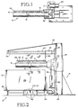
- Fig. 1 is a partial plan view showing an upper portion of a debanding apparatus including a frame and a mandrel (cleaning plate assembly and protective hood omitted for clarity);
- Fig. 2 is an elevation view of the debanding apparatus with portions thereof shown in phantom (protective hood omitted for clarity);
- Fig. 2a is an enlarged, cross-section view of a portion of Fig. 2 showing in more detail a band breaking assembly.
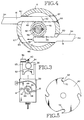
- Fig. 3 is a partial end view showing the mandrel with a pair of band catches extended and the top portion of a piston rod for providing vertical movement, and a cleaning plate for removing coiled banding material (flexible pressure flaps and a protective hood omitted for clarity);
- Fig. 4 is an enlarged sectional view taken substantially along line 4-4 of Fig. 2, showing a pair of band catches in an extended position with one catch shown in a retracted position in phantom;
- Fig. 5 is an elevation view of the band breaking blade detailing band retaining notches;
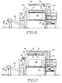
- Fig. 6 is a side elevation of a preferred embodiment of the debanding apparatus during the removal of banding material;
- Fig. 7 is the same view as in Fig. 6 except that the apparatus is shown removing coiled banding material from the mandrel;
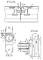
- Fig. 8 is an enlarged sectional end view taken substantially along line 8-8 of Fig. 2, showing a portion of the mandrel, and a support carriage with a pressure flap assembly and a protective hood (hydraulic hoses have been omitted for clarity);
- Fig. 9 is a cross-section view taken substantially along line 9-9 of Fig. 8 showing the mandrel support member and an end portion of the mandrel (the pressure flap assembly and protective hood have been omitted for clarity);
- Fig. 10 is an enlarged cross section taken substantially along line 10-10 of Fig. 2, showing the location of a hydraulic rotary actuator within a mandrel mounting flange;
- Fig. 11 is an enlarged partial sectional view showing a band catch hub with band catches, and the hydraulic rotary actuator attached thereto;
- Fig. 12 is a perspective view of the band breaking blade about to engage a banding wire resting on anvil inserts;
- Fig. 13 is similar to Fig. 12 but shows the band breaking blade engaging the banding wire; and
- Fig. 14 is a partial cross section view of Fig. 13 detailing the interaction of the band breaking blade and the anvil inserts acting on the banding wire.
- Referring now to the drawings, and first to Figs. 1 and 2, a
debanding device 12 is shown to haveframe 14 withvertical support member 22 andhorizontal support member 24.Horizontal support member 24 supports bale receiving table 26 through which band breakingblade 42 passes.Vertical support member 22 provides support for mandrelsupport member 32 and cleaningplate support member 34. - As is better shown in Fig. 9,
mandrel 16 is rotatably located inmandrel collar 77 and supported therein bybearings 76 which are preferably high load type bearings. Mandrelcollar 77 is fixedly attached tomandrel support member 32 which is in turn slidably mounted tovertical support member 22 so as to permit vertical movement thereon by means ofhydraulic cylinder 38 andpiston rod 50. Mandrel 16 is caused to rotate byhydraulic motor 20 anddrive chain 21 rotatingsprocket 78. - Returning again to Figs. 1 and 2, cleaning
plate support member 34 is attached tovertical frame 22 at a location abovemandrel support member 32. To reduce the torque moment acting on the attachment point, cleaningplate support member 34 is further supported bybrace 33.Cleaning plate 36 is mounted for reciprocating axial motion along cleaningplate support member 34.Cleaning plate 36 is driven bymotor 35 andchain 40. In preferred form, cleaningplate 36 includes sliding collar 37 which is in sliding engagement with cleaningplate support member 34. Those persons skilled in the art will recognize that numerous possibilities exist for providing a bearing-type sliding engagement between sliding collar 37 and cleaningplate support member 34. As shown in Fig. 3, cleaningplate 36 is preferably constructed to have two portions: afirst portion 52 is an ultra-high molecular weight plastic while asecond portion 53 is a mild steel plate that is attached to collar 37. - As shown in Fig. 2, pressure flap assembly 39 includes a pair of flexible pressure flaps 41 and
frame member 45 which is attached tomandrel support member 32. Flexible pressure flaps 41, preferably constructed of thick reinforced rubber,contact mandrel 16 in such a manner so as to aid in holdingbanding material 30 in place on rotatingmandrel 16.Frame member 45 is adjustable such that the pressure applied by flexible pressure flaps 41 againstmandrel 16 can be varied by repositioningframe member 45. Typicalflexible pressure flap 41 engagement withmandrel 16 is shown in Fig. 8. - Also attached to frame
member 45, as shown in Fig. 8, isprotective hood 47 which is pivotally attached thereto byhinge 51.Protective hood 47 fits closely overmandrel 16, aiding in the wrapping or winding of bandingmaterial 30 aroundmandrel 16. In addition, plastic end plates (not shown) may be added to the ends ofprotective hood 47 to further aid the winding process of bandingmaterial 30 and increase safety for persons neardebanding device 12.Protective hood 47 pivots onframe member 45 in order to swing out of the way of cleaningplate 36 during the banding material removal process. - Band breaking
blade 42 is mounted for rotatable motion onhorizontal frame 24 using a pair of bearing blocks 43 (see Fig. 2a). As shown in Fig. 2a,band breaking blade 42 is positioned to rotate throughanvil 49 which is made of a hardened steel, e.g., ASTRALOY®, which aids in the breaking of bandingmaterial 30, as is further described below. - Referring now to Figs. 3 and 4, the structure and operation of
mandrel 16 will be discussed in more detail.Mandrel 16 includeshollow portion 44 whereinpinion shaft 56 andpinion gear 46 are located.Pinion shaft 56drives pinion gear 46 which in turn drives band catches 18 to retract or extend by engaging arack portion 48 of band catches 18 (as shown in Fig. 4). - Referring specifically now to Fig. 4,
mandrel 16 is shown in cross-section while band catches 18 are shown in elevation. Eachband catch 18 includes protrudingportion 54 andrack portion 48.Rack portion 48 of eachband catch 18 is in meshing engagement withpinion gear 46.Pinion gear 46 is driven by axially alignedpinion shaft 56 throughkey member 58. Eachband catch 18 extends through amachined opening 60.Openings 60 extend generally radially tomandrel 16, however these openings are spaced sufficiently off-center to allowpinion gear 46 to be placed between the pair ofrack portions 48. In preferred form, band catches 18 andpinion gear 46 are carried byband catch disk 61, as shown in Fig. 11. Eachband catch 18 includesrack end 62 andouter end 64.Mandrel 16 includescavity 66 for receivingrack end 62 ofband catch 18 when it is in its retracted position.Cover plate 67 coverscavity 66. -
Band catch disk 61 described above is preferably machined from a solid disk of steel. As best shown in Fig. 11,band catch disk 61 performs two functions. First, it provides a way to join the two segments ofmandrel 16 together. Second, and more importantly,band catch disk 61 houses band catches 18 by havingopenings 60 through which band catches 18 reciprocate. Hydraulicrotary actuator 72 is mounted toband catch disk 61 so thatpinion shaft 56 extends therein. When subject to a hydraulic pressure, hydraulicrotary actuator 72 causes pinionshaft 56 andpinion gear 46 to rotate, thereby causing band catches 18 to extend or retract. - Referring now to Fig. 5,
band breaking blade 42 is shown. Band breakingblade 42 is preferably constructed from a 22.7 cm ASTRALOY® blade that has been machined and heat treated to approximately 815° C and air cooled. To aid in the engagement and breaking of bandingmaterial 30,band breaking blade 42 hasuniform notches 68 removed from it. Each notch has an internal diameter of approximately 3.5 cm.Internal edge 70 is preferably sharpened to aid in breakingbanding material 30. In addition, the circumferential edge ofband breaking blade 42 is tapered as indicated in Fig. 6 at A to 30 degrees from sectional center before being heat-treated. - Anvil inserts 49 aid
band breaking blade 42 in breakingbanding material 30 by providing side supports to limit bandingmaterial 30 from distributing the force created byband breaking blade 42 beyond a narrow length of material bounded by each edge of anvil inserts 49. The sequential action ofband breaking blade 42 on a length of bandingmaterial 30 is best shown in Figs. 12-14. The combination ofnotches 68 in conjunction with anvil inserts 49 provide a most efficient use of energy for breakingbanding material 30. Moreover, use of anvil inserts 49 localizes the point of breakage, thereby ensuring that band catches 18 will engage a sufficient length of bandingmaterial 30 so that it may be effectively removed frombale 28. - In order to more fully understand the invention, the following is a description of the method for using an embodiment of the apparatus. For convenience, reference may be had to Figs. 6 and 7.
- A
bale 28, which may be of any practical dimension, is placed on a conveyor to be transported to a position on support table 26. Support table 26 is slidable on plastic strips or any other low friction surface so thatbale 28 can be moved progressively undermandrel 16 by a drive system. - Upon activation of the apparatus,
mandrel 16 is rotated bydrive motor 20 anddrive chain 21, at a preferred rate of 18 rpm and band catches 18 are moved to their extended position by pressurizing hydraulicrotary actuator 72. Hydraulicrotary actuator 72cause pinion shaft 56 to rotate until the applied hydraulic pressure is stopped, at whichpoint pinion shaft 56 is locked in place, holding it stationary relative tomandrel 16. When pressure is applied to rotatepinion shaft 56 in the reverse direction, the shaft counter-rotates thereby retracting band catches 18. Supplying hydraulicrotary actuator 72 with fluid are two hydraulic hoses which pass through rotatingunion 80 at the driven end ofmandrel 16. After band catches 18 have attained their extended position,mandrel 16 is lowered byhydraulic cylinder 38 andpiston rod 50 to a positionadjacent bale 28. - Also upon activation of the apparatus,
band breaking blade 42 is rotated by a hydraulic motor and chain (not shown) at a rate below 100 rpm and preferably at 4 to 10 rpm. The direction of rotation is preferably toward the approaching bale so as to pull down on banding material when engaged by anotch 68. After this engagement, bandingmaterial 30 is caused to contact both portions of anvil inserts 49 as best illustrated in Fig. 13. The resulting force from the inherent torque ofband breaking blade 42 in a direction perpendicular to table 26 in combination withsharp edge 70cause banding material 30 to break (See Fig. 14). - As banding
material 30 breaks, it engages one of the band catches 18. Consequently, bandingmaterial 30 begins to wrap aroundmandrel 16 since it is engaged withband catch 18 and held thereto byflexible pressure flap 41 andprotective hood 47.Mandrel 16 is preferably rotated so thatband catch 18 makes a climbing cut, i.e., rotated toward and downwardly into the approachingbale 28. -
Bale 28 continues to move through the apparatus until all bandingmaterials 30 are removed from one surface ofbale 28. Depending upon the type ofbale 28 and number ofbands 30 broken, it may be desired to remove the accumulating bands frommandrel 16. If this is desired,protective hood 47 is caused to pivot away frommandrel 16, thereby exposing the top portion ofmandrel 16 to facilitate the removal of bandingmaterial 30. - Referring to Fig. 7,
mandrel 16 is preferably extended to a position above the bale byhydraulic cylinder 38 andpiston rod 50 so that cleaningblade 36 isadjacent mandrel 16. Hydraulic pressure to hydraulicrotary actuator 72 is reversed so that the closed centered valves reverse the direction of rotation ofpinion shaft 56 which in turn rotatespinion gear 46, thereby retracting band catches 18 intohollow portion 44 ofmandrel 16. After band catches 18 have been retracted, cleaningplate 36 is drawn toward the free end ofmandrel 16 to remove thecoiled banding material 30 intoreceiver 90 which may then deliver the bandingmaterial 30 tochopper 92 viaconveyor 94.Mandrel 16 may continue to rotate during this step or may be stopped.Cleaning plate 36 is then returned to its initial position and the process is repeated. - In order to remove banding
material 30 from other surfaces ofbale 28, the bale may either be repositioned and moved through the debanding apparatus as described above, or a second debanding apparatus may be used wherein themandrel 16 and theband breaking blade 42 are each mounted to a linear actuator capable of movingmandrel 16 andband breaking blade 42 over a different surface ofbale 28, until all of thebands 30 have been removed frombale 28. Depending upon the application,bale 28 may be positioned such that the direction of movement across table 26 is diagonal to plane of rotation ofband breaking blade 42. In this fashion, only one pass through the apparatus may be needed for a bale having any number of perpendicularly intersecting bands. - From the foregoing, there is further modifications, component arrangements, and modes of utilization of the invention which will be apparent to those skilled in the art to which the invention is addressed. The scope of protection is to be determined by the appended claims, interpreted in accordance with the established rules of patent claim interpretation.
- The present invention will find applicability and industrial utility in industries that handle and process baled materials. More particularly, the invention can be used in the wood fiber recycling industry where removal of banding material from bales is desired.
Claims (7)
- A bale debanding device (12) for breaking bands (30) holding a bale (28) together, characterised by:a band breaking blade (42), the blade having at least one band retention notch (68) formed in an edge portion of the blade, the retention notch (68) being shaped to catch and retain a band (30) when the blade is rotated and the band is moved generally perpendicular to the blade; and,an anvil (49), located proximate to the blade (42), having a slot therein to permit the blade to pass therethrough for aiding the blade in breaking the band by reducing and localising the stretching of the band when acted on by the blade.
- A debanding device as claimed in claim 1, further arranged to remove bands from a bale (28), comprising:an axially rotatable mandrel (16) supported by a vertical support (22), the mandrel (16) having an interior portion (44) and an exterior, surface and at least one band catch opening (60) extending from the interior portion to the exterior surface;at least one extendable band catch (18) having a retracted position within the interior portion, and an extended position, the band catch (18) having a band engaging portion (64) extending generally radially outwardly from the exterior surface of the mandrel (16) when in the extended position, and a rack portion (62) which reciprocates within the interior portion of the mandrel; andan independently rotatable pinion gear (46) in meshing contact with the rack portion (48) wherein the pinion gear controls the extension and retraction of the at least one band catch (18) independent of the rotation of the mandrel (16).
- A debanding device as claimed in claim 2, in which a drive motor (20) rotates the mandrel (16), and a rotary actuator (72) rotates the pinion gear thereby controlling extension and retraction of the at least one band catch (18).
- A debanding device as claimed in claim 2 or claim 3, in which a pressure flap assembly (39), including at least one flexible pressure flap (41), is positioned such that the at least one flap (41) is in band engaging contact with the mandrel (16).
- A debanding device as claimed in any of claims 2, 3 or 4, in which a cleaning plate (36) is shaped closely to fit around a portion of the mandrel, and the plate (36) is mounted for axial movement along the mandrel, the plate being axially driven to remove the bands off the mandrel.
- A debanding device as claimed in any proceeding claim, further comprising a bale receiving table (26), the table having a generally planar receiving surface and a supporting structure.
- A debanding device as claimed in any preceding claim, further comprising a motor operably linked to the band breaking blade (42) to impart rotation thereof.
Applications Claiming Priority (3)
| Application Number | Priority Date | Filing Date | Title |
|---|---|---|---|
| US731430 | 1991-07-17 | ||
| US07/731,430 US5216797A (en) | 1991-07-17 | 1991-07-17 | Method and apparatus for debanding a bale |
| PCT/US1992/005862 WO1993001911A1 (en) | 1991-07-17 | 1992-07-17 | Method and apparatus for debanding a bale |
Publications (3)
| Publication Number | Publication Date |
|---|---|
| EP0597938A1 EP0597938A1 (en) | 1994-05-25 |
| EP0597938A4 EP0597938A4 (en) | 1994-12-28 |
| EP0597938B1 true EP0597938B1 (en) | 1997-10-08 |
Family
ID=24939479
Family Applications (1)
| Application Number | Title | Priority Date | Filing Date |
|---|---|---|---|
| EP92916465A Expired - Lifetime EP0597938B1 (en) | 1991-07-17 | 1992-07-17 | Method and apparatus for debanding a bale |
Country Status (6)
| Country | Link |
|---|---|
| US (2) | US5216797A (en) |
| EP (1) | EP0597938B1 (en) |
| JP (1) | JPH06509286A (en) |
| CA (1) | CA2113180C (en) |
| DE (1) | DE69222648D1 (en) |
| WO (1) | WO1993001911A1 (en) |
Families Citing this family (19)
| Publication number | Priority date | Publication date | Assignee | Title |
|---|---|---|---|---|
| US5216797A (en) * | 1991-07-17 | 1993-06-08 | R. Hall Manufacturing Inc. | Method and apparatus for debanding a bale |
| EP0745537B1 (en) * | 1995-06-02 | 1998-07-15 | Lamb-Grays Harbor Co. | Method and apparatus for removing wires from bales of compressible material |
| DE19520248A1 (en) * | 1995-06-02 | 1996-12-05 | Truetzschler Gmbh & Co Kg | Method and device for separating strapping, e.g. B. wires, tapes, bandages and / or packaging (Emballage) of textile fiber bales |
| DE19520247A1 (en) * | 1995-06-02 | 1996-12-05 | Truetzschler Gmbh & Co Kg | Device for determining metallic strapping such as wires, bands or the like for textile fiber bales |
| NL1000912C1 (en) * | 1995-08-01 | 1997-02-04 | Haanschoten Josef Gijsbert | Fast-rotating hand-held circular saw and saw disc therefor. |
| US5811829A (en) † | 1995-08-10 | 1998-09-22 | Arco Chemical Technology, L.P. | Viscosity stable isocyanate-terminated prepolymers and polyoxyalkylene polyether polyols having improved storage stability |
| US5664585A (en) * | 1996-09-10 | 1997-09-09 | Mactavish Machine Manufacturing Co. | Apparatus for cutting tie elements of hands of tobacco |
| US6115904A (en) * | 1997-10-31 | 2000-09-12 | Lamb-Grays Harbor Co. | Rotatable dewiring apparatus and method |
| US6986233B1 (en) * | 2004-08-31 | 2006-01-17 | Illinois Tool Works, Inc. | Bale dewiring system |
| US20060191241A1 (en) * | 2005-02-28 | 2006-08-31 | Deutsch Timothy A | Module wrap removal |
| US20070044603A1 (en) * | 2005-08-24 | 2007-03-01 | Scholtes William J | Automated de-strapper |
| CA2664485C (en) * | 2006-10-27 | 2015-07-14 | Busse/Sji Corporation | Strap removal system |
| AU2008227052A1 (en) * | 2008-09-25 | 2010-04-08 | Visy R & D Pty Ltd | Multifunction tool for depalletising |
| EP2729376A4 (en) * | 2011-06-30 | 2015-05-20 | Mark Gerlinger Lyman | Biomass bale processing system with automatic binding remover |
| ES2424567B2 (en) * | 2013-03-27 | 2014-04-03 | Guerrero Montes Ingeniería, S.L. | Bale Rope Pickup System |
| FI125241B (en) * | 2013-12-23 | 2015-07-31 | Cross Wrap Oy | Device for opening the bale |
| CN108637562B (en) * | 2018-05-22 | 2020-03-24 | 嵊州市恒中机器有限公司 | Positioning tool for welding and assembling rear backrest of straightening type vehicle head |
| CN111842540B (en) * | 2020-07-20 | 2022-07-26 | 湖南森钢新材料科技股份有限公司 | Steel coil supporting and fixing structure of steel coil crimping machine |
| CN114044223B (en) * | 2021-10-29 | 2023-04-04 | 山鹰国际控股股份公司 | Hydraulic broken wire initial loose device for paper package broken wire |
Family Cites Families (21)
| Publication number | Priority date | Publication date | Assignee | Title |
|---|---|---|---|---|
| US1076920A (en) * | 1912-08-13 | 1913-10-28 | Harry M Sprecher | Winding-machine. |
| US1291669A (en) * | 1917-02-28 | 1919-01-14 | Bridgeport Brass Co | Coiling apparatus. |
| US1859051A (en) * | 1930-04-26 | 1932-05-17 | Richter Alfred | Curtain wrapping machine |
| US1956429A (en) * | 1932-03-02 | 1934-04-24 | Firestone Tire & Rubber Co | Slitting machine |
| US1998893A (en) * | 1932-09-28 | 1935-04-23 | Charles B Cole | Boring and facing tool head |
| US2820282A (en) * | 1954-08-06 | 1958-01-21 | Jack B Tropp | Apparatus for removing ties from packages |
| US2839258A (en) * | 1955-11-02 | 1958-06-17 | Delbert G Jacobson | Wire winding spool mechanism |
| US2992592A (en) * | 1956-10-18 | 1961-07-18 | Agfa Ag | Masking frame for making enlargements |
| US2941743A (en) * | 1958-07-31 | 1960-06-21 | United States Steel Corp | Wire fabric reeling mandrel with rotatably retractable winding hooks |
| US3006565A (en) * | 1960-06-30 | 1961-10-31 | Eugene V Pelletier | Bobbin clutch |
| US3281092A (en) * | 1961-08-17 | 1966-10-25 | Schultz Sales Corp | Self-adjusting mill roll supporting mandrel |
| US3279010A (en) * | 1965-06-28 | 1966-10-18 | Peter A Misanchuk | Cord-length varying device |
| US3513522A (en) * | 1967-04-03 | 1970-05-26 | Victor J Thomson | Unbaling machine |
| SE390918B (en) * | 1973-11-28 | 1977-01-31 | Stridsberg & Bjorck Ab | BULLERAVSTORD CIRKELSAGKLINGA |
| DE2821336C2 (en) * | 1978-05-16 | 1980-07-31 | B+G-Foerdertechnik Gmbh, 5350 Euskirchen | Winding head |
| US4270428A (en) * | 1979-07-25 | 1981-06-02 | Black & Decker Inc. | Kerf guide and cautionary marker for a power driven tool |
| DE3229765A1 (en) * | 1982-08-10 | 1984-02-16 | GAO Gesellschaft für Automation und Organisation mbH, 8000 München | DEVICE FOR REMOVING A BANDEROLE FROM A BUNCH OF SHEETS |
| US4871619A (en) * | 1983-11-30 | 1989-10-03 | International Business Machines Corporation | Electronic components comprising polymide dielectric layers |
| JPH03111236A (en) * | 1989-09-19 | 1991-05-13 | Tateno Kikai Seisakusho:Kk | Unpacking and processing method for packaged sheet paper |
| US5079826A (en) * | 1990-05-15 | 1992-01-14 | Lamb-Grays Harbor Co. | Wire cutting and removal apparatus |
| US5216797A (en) * | 1991-07-17 | 1993-06-08 | R. Hall Manufacturing Inc. | Method and apparatus for debanding a bale |
-
1991
- 1991-07-17 US US07/731,430 patent/US5216797A/en not_active Expired - Lifetime
-
1992
- 1992-07-17 DE DE69222648T patent/DE69222648D1/en not_active Expired - Lifetime
- 1992-07-17 WO PCT/US1992/005862 patent/WO1993001911A1/en active IP Right Grant
- 1992-07-17 CA CA002113180A patent/CA2113180C/en not_active Expired - Fee Related
- 1992-07-17 EP EP92916465A patent/EP0597938B1/en not_active Expired - Lifetime
- 1992-07-17 JP JP5502896A patent/JPH06509286A/en active Pending
-
1993
- 1993-06-03 US US08/071,459 patent/US5400493A/en not_active Expired - Lifetime
Also Published As
| Publication number | Publication date |
|---|---|
| US5216797A (en) | 1993-06-08 |
| DE69222648D1 (en) | 1997-11-13 |
| CA2113180A1 (en) | 1993-02-04 |
| CA2113180C (en) | 1999-01-05 |
| US5400493A (en) | 1995-03-28 |
| EP0597938A1 (en) | 1994-05-25 |
| EP0597938A4 (en) | 1994-12-28 |
| JPH06509286A (en) | 1994-10-20 |
| WO1993001911A1 (en) | 1993-02-04 |
Similar Documents
| Publication | Publication Date | Title |
|---|---|---|
| EP0597938B1 (en) | Method and apparatus for debanding a bale | |
| US4929141A (en) | Bale-opening method and apparatus | |
| US4104792A (en) | Wheel and tire cutter | |
| US8707532B2 (en) | Method for removing wires from a bale | |
| DE3330489A1 (en) | PACKING MACHINE | |
| DE19650943B4 (en) | Machine for unpacking a bale, in particular a tobacco bale, from a packaging | |
| US4250783A (en) | Bale cutting apparatus | |
| CN113800290A (en) | Film packing plant and film rolling packing integration equipment | |
| US11458646B2 (en) | Method and apparatus for removing wrapping from rolls | |
| EP2121453A1 (en) | Bale tongs to be connected to a working machine | |
| US5375316A (en) | Bale wire stripping system | |
| US5024386A (en) | Tire converting apparatus and method | |
| US4922976A (en) | Apparatus for removing branches from and for crosscutting treetrunks | |
| SE531004C2 (en) | Device and method for compressing wood | |
| US4738172A (en) | Apparatus for debeading a scrap tire | |
| US4802635A (en) | Apparatus and method for compacting a scrap tire | |
| US4205573A (en) | Method and apparatus for automatically cutting long rolls of microfoam material and the like into shorter sub-rolls | |
| CN110834774A (en) | Portable shearing mechanism is taken in packing | |
| US4729272A (en) | Wire rope salvaging apparatus | |
| CN109328886B (en) | Auricularia auricula picking machine | |
| US5584215A (en) | Tire cutting apparatus | |
| CN219905021U (en) | Automatic cut bag baffle mechanism | |
| DK181098B1 (en) | System for de-wiring bales | |
| CN216807656U (en) | Coiling mechanism is used in production of industry conveyer belt | |
| CN220008014U (en) | Bale strip cutting device |
Legal Events
| Date | Code | Title | Description |
|---|---|---|---|
| PUAI | Public reference made under article 153(3) epc to a published international application that has entered the european phase |
Free format text: ORIGINAL CODE: 0009012 |
|
| 17P | Request for examination filed |
Effective date: 19940217 |
|
| AK | Designated contracting states |
Kind code of ref document: A1 Designated state(s): DE FR GB IT |
|
| A4 | Supplementary search report drawn up and despatched |
Effective date: 19941108 |
|
| AK | Designated contracting states |
Kind code of ref document: A4 Designated state(s): DE FR GB IT |
|
| 17Q | First examination report despatched |
Effective date: 19960105 |
|
| GRAG | Despatch of communication of intention to grant |
Free format text: ORIGINAL CODE: EPIDOS AGRA |
|
| GRAH | Despatch of communication of intention to grant a patent |
Free format text: ORIGINAL CODE: EPIDOS IGRA |
|
| GRAH | Despatch of communication of intention to grant a patent |
Free format text: ORIGINAL CODE: EPIDOS IGRA |
|
| GRAA | (expected) grant |
Free format text: ORIGINAL CODE: 0009210 |
|
| AK | Designated contracting states |
Kind code of ref document: B1 Designated state(s): DE FR GB IT |
|
| PG25 | Lapsed in a contracting state [announced via postgrant information from national office to epo] |
Ref country code: IT Free format text: LAPSE BECAUSE OF FAILURE TO SUBMIT A TRANSLATION OF THE DESCRIPTION OR TO PAY THE FEE WITHIN THE PRE;WARNING: LAPSES OF ITALIAN PATENTS WITH EFFECTIVE DATE BEFORE 2007 MAY HAVE OCCURRED AT ANY TIME BEFORE 2007. THE CORRECT EFFECTIVE DATE MAY BE DIFFERENT FROM THE ONE RECORDED.SCRIBED TIME-LIMIT Effective date: 19971008 Ref country code: FR Free format text: LAPSE BECAUSE OF FAILURE TO SUBMIT A TRANSLATION OF THE DESCRIPTION OR TO PAY THE FEE WITHIN THE PRESCRIBED TIME-LIMIT Effective date: 19971008 |
|
| REF | Corresponds to: |
Ref document number: 69222648 Country of ref document: DE Date of ref document: 19971113 |
|
| PG25 | Lapsed in a contracting state [announced via postgrant information from national office to epo] |
Ref country code: DE Free format text: LAPSE BECAUSE OF FAILURE TO SUBMIT A TRANSLATION OF THE DESCRIPTION OR TO PAY THE FEE WITHIN THE PRESCRIBED TIME-LIMIT Effective date: 19980109 |
|
| EN | Fr: translation not filed | ||
| PLBE | No opposition filed within time limit |
Free format text: ORIGINAL CODE: 0009261 |
|
| STAA | Information on the status of an ep patent application or granted ep patent |
Free format text: STATUS: NO OPPOSITION FILED WITHIN TIME LIMIT |
|
| 26N | No opposition filed | ||
| PGFP | Annual fee paid to national office [announced via postgrant information from national office to epo] |
Ref country code: GB Payment date: 19990714 Year of fee payment: 8 |
|
| PG25 | Lapsed in a contracting state [announced via postgrant information from national office to epo] |
Ref country code: GB Free format text: LAPSE BECAUSE OF NON-PAYMENT OF DUE FEES Effective date: 20000717 |
|
| GBPC | Gb: european patent ceased through non-payment of renewal fee |
Effective date: 20000717 |