EP0597866B1 - Steuerkörper für einen flüssigkeitsringverdichter - Google Patents
Steuerkörper für einen flüssigkeitsringverdichter Download PDFInfo
- Publication number
- EP0597866B1 EP0597866B1 EP92912899A EP92912899A EP0597866B1 EP 0597866 B1 EP0597866 B1 EP 0597866B1 EP 92912899 A EP92912899 A EP 92912899A EP 92912899 A EP92912899 A EP 92912899A EP 0597866 B1 EP0597866 B1 EP 0597866B1
- Authority
- EP
- European Patent Office
- Prior art keywords
- outlet
- cross
- delivery slot
- impeller
- section
- Prior art date
- Legal status (The legal status is an assumption and is not a legal conclusion. Google has not performed a legal analysis and makes no representation as to the accuracy of the status listed.)
- Expired - Lifetime
Links
- 239000007788 liquid Substances 0.000 title claims abstract description 15
- 238000011144 upstream manufacturing Methods 0.000 claims abstract description 3
- 230000007423 decrease Effects 0.000 claims description 3
- 238000007906 compression Methods 0.000 description 1
- 230000002349 favourable effect Effects 0.000 description 1
- 238000007654 immersion Methods 0.000 description 1
- 238000000034 method Methods 0.000 description 1
Images
Classifications
-
- F—MECHANICAL ENGINEERING; LIGHTING; HEATING; WEAPONS; BLASTING
- F04—POSITIVE - DISPLACEMENT MACHINES FOR LIQUIDS; PUMPS FOR LIQUIDS OR ELASTIC FLUIDS
- F04C—ROTARY-PISTON, OR OSCILLATING-PISTON, POSITIVE-DISPLACEMENT MACHINES FOR LIQUIDS; ROTARY-PISTON, OR OSCILLATING-PISTON, POSITIVE-DISPLACEMENT PUMPS
- F04C19/00—Rotary-piston pumps with fluid ring or the like, specially adapted for elastic fluids
- F04C19/005—Details concerning the admission or discharge
- F04C19/007—Port members in the form of side plates
Definitions
- the invention relates to a control body for a liquid ring compressor, on which control body in each case at least one suction and one pressure slot as well as several valve-controlled outlet openings upstream of the pressure slot are provided.
- Such a control body is known from DE-B-27 31 451.
- a blade cell delimited by two blades of the impeller always covers only a portion of the outlet area consisting of the outlet openings and the pressure slot. This means that only the outlet openings located in this area are effective for the gas outlet.
- the total outlet cross-section effective for the gas outlet results from the individual free cross-sections of the outlet openings located in the region of a blade cell.
- the size and position of the outlet openings in the known control body is primarily determined by the arrangement of the valve flaps assigned to the individual outlet openings. Thus, the total outlet cross-section available in each case does not optimally correspond to the conditions prevailing in the corresponding area.
- the invention has for its object to provide a control body for a liquid ring compressor so that the conditions in the outlet region of the liquid ring compressor are improved.
- the outlet openings are dimensioned in their cross-section and / or arranged such that each of the the total outlet cross-section resulting from a vane cell of the compressor impeller covered at least approximately continuously decreases from a maximum value in the initial area of the outlet starting at the angle of rotation of the impeller up to the cross-sectional profile specified by the pressure slot.
- Pressure surges are largely avoided or at least greatly damped by the uniform course of the effective total outlet cross-section from the beginning of the gas discharge to the completion of the compression process. This leads to a smoother running of the compressor and to a noise reduction. There is also an improvement in efficiency.
- the pressure slot is designed in such a way that there is a continuous, continuous course for the outlet cross-section from the maximum value to the end value zero which occurs at the end of the pressure slot.
- a liquid ring compressor consists of a round housing in which an impeller equipped with blades is rotatably arranged.
- the impeller is offset with its axis of rotation relative to the center axis of the housing. Because of this eccentricity, the degree of immersion of the blades of the impeller in the liquid ring moves between a minimum and a maximum value during one revolution.
- the volume of the control disks which are delimited by two successive blades, the impeller hub and the liquid ring, and the control disks arranged on the end face of the impeller also varies accordingly Bucket cells between a minimum and a maximum.
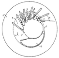
- Such a control disk 1 has a suction slot 2 and a pressure slot 3. With respect to the conveying direction (arrow 4) of the liquid ring compressor, a plurality of outlet openings 5 are formed in the control disk 1 in front of the pressure slot 3, which together with the pressure slot 3 form the outlet.
- some blades 6 of the impeller and the liquid ring 7 of the liquid ring compressor are also indicated. Between each two adjacent blades 6 there is a blade cell 8 which is delimited radially on the outside by the liquid ring 7 and radially on the inside by the hub 9 of the impeller. On the face side, the blade cells 8 are covered either by control disks 1 arranged on both sides of the impeller or by a control disk 1 arranged on one side of the impeller and a smooth housing wall located on the other end face of the impeller.
- the cross section of the outlet openings 5 is dimensioned and / or their arrangement on the control disk is such that the total outlet cross section of the outlet openings each covered by a vane cell 8 rapidly increases to its greatest value at the beginning of the ejection process and from then on as possible as the vane cell 8 continues to rotate decreases continuously. This results in an approximately triangular course for the effective outlet cross section over the angle of rotation of the impeller.
- a flat control disk 1 has been shown and described as an exemplary embodiment of the control body.
- the control body can, as known per se, be conical and axially concentric in the impeller.
Landscapes
- Engineering & Computer Science (AREA)
- Mechanical Engineering (AREA)
- General Engineering & Computer Science (AREA)
- Structures Of Non-Positive Displacement Pumps (AREA)
- Applications Or Details Of Rotary Compressors (AREA)
Abstract
Description
- Die Erfindung betrifft einen Steuerkörper für einen Flüssigkeitsringverdichter, an welchem Steuerkörper jeweils mindestens ein Saug- und ein Druckschlitz sowie mehrere, dem Druckschlitz vorgeordnete, ventilgesteuerte Auslaßöffnungen vorgesehen sind.
- Ein solcher Steuerkörper ist durch die DE-B-27 31 451 bekannt. Bei einem solchen Steuerkörper überdeckt eine durch zwei Schaufeln des Laufrades abgegrenzte Schaufelzelle stets nur einen Abschnitt des aus den Auslaßöffnungen und dem Druckschlitz bestehenden Auslaßbereiches. Damit sind für den Gasauslaß nur die jeweils in diesem Bereich befindlichen Auslaßöffnungen wirksam. Der für den Gasauslaß wirksame Gesamtauslaßquerschnitt ergibt sich aus den einzelnen freien Querschnitten der jeweils im Bereich einer Schaufelzelle befindlichen Auslaßöffnungen. Die Größe und Lage der Auslaßöffnungen wird bei dem bekannten Steuerkörper vor allem durch die Anordnung der den einzelnen Auslaßöffnungen zugeordneten Ventilklappen bestimmt. Somit entspricht der jeweils zur Verfügung stehende Gesamtauslaßquerschnitt nicht optimal den jeweils in dem entsprechenden Bereich vorliegenden Verhältnissen.
- Der Erfindung liegt die Aufgabe zugrunde, einen Steuerkörper für einen Flüssigkeitsringverdichter so auszubilden, daß die Verhältnisse im Auslaßbereich des Flüssigkeitsringverdichters verbessert sind.
- Die Lösung der gestellten Aufgabe gelingt nach der Erfindung dadurch, daß die Auslaßöffnungen in ihrem Querschnitt so bemessen und/oder derart angeordnet sind, daß der jeweils aus den von einer Schaufelzelle des Verdichterlaufrades überdeckten Auslaßöffnungen resultierende Gesamtaustrittsquerschnitt von einem im Anfangsbereich des Auslasses liegenden Maximalwert beginnend über dem Drehwinkel des Laufrades zumindest angenähert kontinuierlich bis zu dem durch den Druckschlitz vorgegebenen Querschnittsverlauf abnimmt. Durch den gleichmäßigen Verlauf des jeweils wirksamen Gesamtauslaßquerschnitts vom Beginn des Gasausschubes bis zum Abschluß des Verdichtungsvorganges werden Druckstöße weitgehend vermieden oder zumindest stark gedämpft. Dies führt zu einer größeren Laufruhe des Verdichters und zu einer Geräuschreduzierung. Außerdem ergibt sich eine Wirkungsgradverbesserung.
- Besonders vorteilhaft ist es, wenn der Druckschlitz derart gestaltet ist, daß sich für den Austrittsquerschnitt von dem Maximalwert beginnend bis zu dem am Ende des Druckschlitzes eintretenden Endwert Null ein durchgehend kontinuierlicher Verlauf ergibt.
- Anhand einer in der Zeichnung dargestellten, ebenen Steuerscheibe eines Flüssigkeitsringverdichters wird die Erfindung nachfolgend näher beschrieben.
- Wie aus dem Stand der Technik bekannt, besteht ein Flüssigkeitsringverdichter aus einem runden Gehäuse, in dem ein mit Schaufeln bestücktes Laufrad drehbar angeordnet ist. Das Laufrad ist dabei mit seiner Drehachse gegenüber der Mittenachse des Gehäuses exzentrisch versetzt. Aufgrund dieser Exzentrizität bewegt sich das Maß der Eintauchtiefe der Schaufeln des Laufrades in den Flüssigkeitsring während einer Umdrehung zwischen einem Minimal- und Maximalwert. Dementsprechend variiert auch das Volumen der von zwei aufeinanderfolgenden Schaufeln, der Laufradnabe und dem Flüssigkeitsring sowie den stirnseitig zum Laufrad angeordneten Steuerscheiben begrenzten Schaufelzellen zwischen einem Minimum und einem Maximum. In dem in Drehrichtung vor dem Volumenmaximum liegenden Bereich wird ein zu verdichtendes Gas in die jeweilige Schaufelzelle eingesaugt und im Bereich vor dem Volumenminimum verdichtet wieder ausgestoßen. Das Ansaugen und Ausstoßen erfolgt über die stirnseitig zum Laufrad entweder auf beiden Seiten oder nur auf einer Seite angeordnete Steuerscheibe, wie sie in der Zeichnung dargestellt ist.
- Eine solche Steuerscheibe 1 weist einen Saugschlitz 2 und einen Druckschlitz 3 auf. Mit Bezug auf die Förderrichtung (Pfeil 4) des Flüssigkeitsringverdichters sind vor dem Druckschlitz 3 mehrere Auslaßöffnungen 5 in der Steuerscheibe 1 ausgebildet, die zusammen mit dem Druckschlitz 3 den Auslaß bilden. In der Zeichnung sind ferner einige Schaufeln 6 des Laufrades und der Flüssigkeitsring 7 des Flüssigkeitsringverdichters angedeutet. Zwischen jeweils zwei benachbarten Schaufeln 6 besteht eine Schaufelzelle 8, die radial außen durch den Flüssigkeitsring 7 und radial innen durch die Nabe 9 des Laufrades begrenzt wird. Stirnseitig sind die Schaufelzellen 8 entweder durch beidseitig zum Laufrad angeordnete Steuerscheiben 1 oder durch eine auf der einen Seite des Laufrades angeordnete Steuerscheibe 1 und eine auf der anderen Stirnseite des Laufrades befindliche glatte Gehäusewand abgedeckt.
- Der Querschnitt der Auslaßöffnungen 5 ist so bemessen und/oder deren Anordnung an der Steuerscheibe so getroffen, daß der Gesamtauslaßquerschnitt der jeweils von einer Schaufelzelle 8 überdeckten Auslaßöffnungen zum Beginn des Ausstoßvorganges rasch auf seinen größten Wert ansteigt und von da an bei Weiterdrehung der Schaufelzelle 8 möglichst kontinuierlich wieder abnimmt. Damit ergibt sich für den wirksamen Auslaßquerschnitt über dem Drehwinkel des Laufrades ein etwa dreieckförmiger Verlauf.
- Bei einem solchen Verlauf des Auslaßquerschnittes werden Druckstöße beim Ausströmen des verdichteten Gases aus den Schaufelzellen 8 weitgehend vermieden. Dies wirkt sich günstig auf das Lauf- und Geräuschverhalten des Flüssigkeitsringverdichters aus. Außerdem konnte eine Verbesserung des Wirkungsgrades festgestellt werden.
- Als Ausführungsbeispiel für den Steuerkörper wurde eine ebene Steuerscheibe 1 dargestellt und beschrieben. Der Steuerkörper kann auch, wie an sich bekannt, kegelförmig ausgebildet und axial konzentrisch in das Laufrad eingesetzt sein.
Claims (2)
- Steuerkörper für einen Flüssigkeitsringverdichter, an welchem Steuerkörper jeweils mindestens ein Saug- und ein Druckschlitz (2 und 3) sowie mehrere dem Druckschlitz (3) vorgeordnete, ventilgesteuerte Auslaßöffnungen (5) vorgesehen sind, dadurch gekennzeichnet,
daß die Auslaßöffnungen (5) in ihrem Querschnitt so bemessen und derart angeordnet sind, daß der jeweils aus den von einer Schaufelzelle (8) des Verdichterlaufrades überdeckten Auslaßöffnungen (5) resultierende Gesamtaustrittsquerschnitt von einem im Anfangsbereich des Auslasses (3;5) liegenden Maximalwert beginnend über dem Drehwinkel des Laufrades zumindest angenähert kontinuierlich bis zu dem durch den Druckschlitz vorgegebenen Querschnittsverlauf abnimmt. - Steuerkörper nach Anspruch 1,
dadurch gekennzeichnet,
daß der Druckschlitz (3) derart gestaltet ist, daß sich für den Austrittsquerschnitt von dem Maximalwert beginnend bis zu dem am Ende des Druckschlitzes (3) eintretenden Endwert Null ein durchgehend kontinuierlicher Verlauf ergibt.
Applications Claiming Priority (3)
| Application Number | Priority Date | Filing Date | Title |
|---|---|---|---|
| DE4126322A DE4126322A1 (de) | 1991-08-08 | 1991-08-08 | Steuerkoerper fuer einen fluessigkeitsringverdichter |
| DE4126322 | 1991-08-08 | ||
| PCT/DE1992/000553 WO1993003281A1 (de) | 1991-08-08 | 1992-07-03 | Steuerkörper für einen flüssigkeitsringverdichter |
Publications (2)
| Publication Number | Publication Date |
|---|---|
| EP0597866A1 EP0597866A1 (de) | 1994-05-25 |
| EP0597866B1 true EP0597866B1 (de) | 1995-01-25 |
Family
ID=6437956
Family Applications (1)
| Application Number | Title | Priority Date | Filing Date |
|---|---|---|---|
| EP92912899A Expired - Lifetime EP0597866B1 (de) | 1991-08-08 | 1992-07-03 | Steuerkörper für einen flüssigkeitsringverdichter |
Country Status (5)
| Country | Link |
|---|---|
| EP (1) | EP0597866B1 (de) |
| JP (1) | JPH06509622A (de) |
| DE (2) | DE4126322A1 (de) |
| FI (1) | FI105583B (de) |
| WO (1) | WO1993003281A1 (de) |
Family Cites Families (5)
| Publication number | Priority date | Publication date | Assignee | Title |
|---|---|---|---|---|
| DE258021C (de) * | ||||
| DE2704863A1 (de) * | 1977-02-05 | 1978-08-10 | Kloeckner Humboldt Deutz Ag | Rueckschlagventil fuer eine fluessigkeitsring-gaspumpe |
| DE2731451C2 (de) * | 1977-07-12 | 1978-12-14 | Siemens Ag, 1000 Berlin Und 8000 Muenchen | Flüssigkeitsringverdichter oder -vakuumpumpe |
| DE8708108U1 (de) * | 1987-06-09 | 1987-08-06 | Siemens AG, 1000 Berlin und 8000 München | Flüssigkeitsringmaschine |
| DE58902779D1 (de) * | 1989-06-05 | 1992-12-24 | Siemens Ag | Fluessigkeitsringverdichter. |
-
1991
- 1991-08-08 DE DE4126322A patent/DE4126322A1/de not_active Withdrawn
-
1992
- 1992-07-03 WO PCT/DE1992/000553 patent/WO1993003281A1/de not_active Ceased
- 1992-07-03 DE DE59201306T patent/DE59201306D1/de not_active Expired - Lifetime
- 1992-07-03 JP JP5503163A patent/JPH06509622A/ja active Pending
- 1992-07-03 EP EP92912899A patent/EP0597866B1/de not_active Expired - Lifetime
-
1994
- 1994-02-07 FI FI940547A patent/FI105583B/fi active
Also Published As
| Publication number | Publication date |
|---|---|
| FI940547L (fi) | 1994-02-07 |
| DE59201306D1 (de) | 1995-03-09 |
| FI105583B (fi) | 2000-09-15 |
| DE4126322A1 (de) | 1993-02-11 |
| WO1993003281A1 (de) | 1993-02-18 |
| FI940547A0 (fi) | 1994-02-07 |
| EP0597866A1 (de) | 1994-05-25 |
| JPH06509622A (ja) | 1994-10-27 |
Similar Documents
| Publication | Publication Date | Title |
|---|---|---|
| EP0112932B1 (de) | Radialventilator mit rückwärts gekrümmten, profilierten Schaufeln | |
| EP2627907B1 (de) | Seitenkanalgebläse, insbesondere sekundärluftgebläse für eine verbrennungskraftmaschine | |
| DE1817430A1 (de) | Regenerativkompressor | |
| EP3527832A1 (de) | Spiralgehäuse eines radialventilators | |
| DE19722353A1 (de) | Kreiselpumpe mit einer Einlaufleiteinrichtung | |
| DE3238972A1 (de) | Horizontal geteiltes gehaeuse einer stroemungsmaschine | |
| EP0118769A2 (de) | Mehrstufige Deckbandturbine | |
| EP0363503B1 (de) | Pumpenstufe für eine Hochvakuumpumpe | |
| EP0627561A1 (de) | Radialgebläse | |
| DE4113394C3 (de) | Ringkanalgebläse | |
| EP0567874B1 (de) | Strömungsmaschine zur Gasverdichtung | |
| DE69106179T2 (de) | Diagonal-Verdichter. | |
| DE3912279C2 (de) | ||
| DE3210161C1 (de) | Fluessigkeitsringkompressor fuer Gase | |
| WO1993003281A1 (de) | Steuerkörper für einen flüssigkeitsringverdichter | |
| DE890256C (de) | Fluessigkeitsring-Verdichter | |
| EP0808424A1 (de) | Seitenkanalpumpe | |
| EP1029180A1 (de) | Seitenkanalkreiselpumpe | |
| EP3608544B1 (de) | Kreiselpumpe | |
| DE2049460A1 (de) | Flussigkeits Flugelradpumpe | |
| DE2230773A1 (de) | Verdraengermaschine | |
| DE2430117B1 (de) | Mehrstufiger Axialverdichter | |
| DE1280464C2 (de) | Luftverdichter mit einer Radialstufe und einer vorgeschalteten Axialstufe | |
| DE966006C (de) | Fluessigkeitsring-Gaspumpe | |
| WO1995019503A1 (de) | Mit entlastungsöffnungen ausgestattetes kreiselpumpenlaufrad aus blech |
Legal Events
| Date | Code | Title | Description |
|---|---|---|---|
| PUAI | Public reference made under article 153(3) epc to a published international application that has entered the european phase |
Free format text: ORIGINAL CODE: 0009012 |
|
| 17P | Request for examination filed |
Effective date: 19931005 |
|
| AK | Designated contracting states |
Kind code of ref document: A1 Designated state(s): DE FR GB IT |
|
| 17Q | First examination report despatched |
Effective date: 19940330 |
|
| GRAA | (expected) grant |
Free format text: ORIGINAL CODE: 0009210 |
|
| AK | Designated contracting states |
Kind code of ref document: B1 Designated state(s): DE FR GB IT |
|
| REF | Corresponds to: |
Ref document number: 59201306 Country of ref document: DE Date of ref document: 19950309 |
|
| GBT | Gb: translation of ep patent filed (gb section 77(6)(a)/1977) |
Effective date: 19950303 |
|
| ITF | It: translation for a ep patent filed | ||
| ET | Fr: translation filed | ||
| PLBE | No opposition filed within time limit |
Free format text: ORIGINAL CODE: 0009261 |
|
| STAA | Information on the status of an ep patent application or granted ep patent |
Free format text: STATUS: NO OPPOSITION FILED WITHIN TIME LIMIT |
|
| 26N | No opposition filed | ||
| PGFP | Annual fee paid to national office [announced via postgrant information from national office to epo] |
Ref country code: GB Payment date: 19980623 Year of fee payment: 7 |
|
| PGFP | Annual fee paid to national office [announced via postgrant information from national office to epo] |
Ref country code: FR Payment date: 19980729 Year of fee payment: 7 |
|
| PG25 | Lapsed in a contracting state [announced via postgrant information from national office to epo] |
Ref country code: GB Free format text: LAPSE BECAUSE OF NON-PAYMENT OF DUE FEES Effective date: 19990703 |
|
| PG25 | Lapsed in a contracting state [announced via postgrant information from national office to epo] |
Ref country code: FR Free format text: THE PATENT HAS BEEN ANNULLED BY A DECISION OF A NATIONAL AUTHORITY Effective date: 19990731 |
|
| GBPC | Gb: european patent ceased through non-payment of renewal fee |
Effective date: 19990703 |
|
| REG | Reference to a national code |
Ref country code: FR Ref legal event code: ST |
|
| PGFP | Annual fee paid to national office [announced via postgrant information from national office to epo] |
Ref country code: IT Payment date: 20100728 Year of fee payment: 19 Ref country code: DE Payment date: 20100728 Year of fee payment: 19 |
|
| PG25 | Lapsed in a contracting state [announced via postgrant information from national office to epo] |
Ref country code: DE Free format text: LAPSE BECAUSE OF NON-PAYMENT OF DUE FEES Effective date: 20120201 |
|
| REG | Reference to a national code |
Ref country code: DE Ref legal event code: R119 Ref document number: 59201306 Country of ref document: DE Effective date: 20120201 |
|
| PG25 | Lapsed in a contracting state [announced via postgrant information from national office to epo] |
Ref country code: IT Free format text: LAPSE BECAUSE OF NON-PAYMENT OF DUE FEES Effective date: 20110703 |