EP0597622A1 - Probenträgervorrichtung für ein Rastermikroskop - Google Patents
Probenträgervorrichtung für ein Rastermikroskop Download PDFInfo
- Publication number
- EP0597622A1 EP0597622A1 EP93308790A EP93308790A EP0597622A1 EP 0597622 A1 EP0597622 A1 EP 0597622A1 EP 93308790 A EP93308790 A EP 93308790A EP 93308790 A EP93308790 A EP 93308790A EP 0597622 A1 EP0597622 A1 EP 0597622A1
- Authority
- EP
- European Patent Office
- Prior art keywords
- carriage
- sample
- actuator
- scanning probe
- cylindrical sleeve
- Prior art date
- Legal status (The legal status is an assumption and is not a legal conclusion. Google has not performed a legal analysis and makes no representation as to the accuracy of the status listed.)
- Granted
Links
- 239000000523 sample Substances 0.000 title claims abstract description 188
- 239000000463 material Substances 0.000 claims abstract description 8
- 230000004907 flux Effects 0.000 claims description 14
- 230000000903 blocking effect Effects 0.000 claims description 5
- 239000000696 magnetic material Substances 0.000 claims description 4
- 238000005259 measurement Methods 0.000 description 11
- 230000033001 locomotion Effects 0.000 description 8
- 230000000712 assembly Effects 0.000 description 4
- 238000000429 assembly Methods 0.000 description 4
- 238000003384 imaging method Methods 0.000 description 4
- 238000000034 method Methods 0.000 description 3
- 239000004593 Epoxy Substances 0.000 description 2
- 238000013459 approach Methods 0.000 description 2
- 238000012937 correction Methods 0.000 description 2
- 230000000694 effects Effects 0.000 description 2
- 238000002955 isolation Methods 0.000 description 2
- 238000004519 manufacturing process Methods 0.000 description 2
- 239000007787 solid Substances 0.000 description 2
- 239000000126 substance Substances 0.000 description 2
- 229910001374 Invar Inorganic materials 0.000 description 1
- XUIMIQQOPSSXEZ-UHFFFAOYSA-N Silicon Chemical compound [Si] XUIMIQQOPSSXEZ-UHFFFAOYSA-N 0.000 description 1
- 229910000831 Steel Inorganic materials 0.000 description 1
- 239000013078 crystal Substances 0.000 description 1
- 238000013016 damping Methods 0.000 description 1
- 238000013461 design Methods 0.000 description 1
- 238000011161 development Methods 0.000 description 1
- 230000018109 developmental process Effects 0.000 description 1
- 238000006073 displacement reaction Methods 0.000 description 1
- 230000003993 interaction Effects 0.000 description 1
- 230000002452 interceptive effect Effects 0.000 description 1
- 239000010959 steel Substances 0.000 description 1
- 230000036962 time dependent Effects 0.000 description 1
- 238000013519 translation Methods 0.000 description 1
Images


Classifications
-
- H—ELECTRICITY
- H01—ELECTRIC ELEMENTS
- H01J—ELECTRIC DISCHARGE TUBES OR DISCHARGE LAMPS
- H01J37/00—Discharge tubes with provision for introducing objects or material to be exposed to the discharge, e.g. for the purpose of examination or processing thereof
- H01J37/02—Details
- H01J37/20—Means for supporting or positioning the objects or the material; Means for adjusting diaphragms or lenses associated with the support
-
- G—PHYSICS
- G01—MEASURING; TESTING
- G01Q—SCANNING-PROBE TECHNIQUES OR APPARATUS; APPLICATIONS OF SCANNING-PROBE TECHNIQUES, e.g. SCANNING PROBE MICROSCOPY [SPM]
- G01Q70/00—General aspects of SPM probes, their manufacture or their related instrumentation, insofar as they are not specially adapted to a single SPM technique covered by group G01Q60/00
- G01Q70/02—Probe holders
- G01Q70/04—Probe holders with compensation for temperature or vibration induced errors
-
- Y—GENERAL TAGGING OF NEW TECHNOLOGICAL DEVELOPMENTS; GENERAL TAGGING OF CROSS-SECTIONAL TECHNOLOGIES SPANNING OVER SEVERAL SECTIONS OF THE IPC; TECHNICAL SUBJECTS COVERED BY FORMER USPC CROSS-REFERENCE ART COLLECTIONS [XRACs] AND DIGESTS
- Y10—TECHNICAL SUBJECTS COVERED BY FORMER USPC
- Y10S—TECHNICAL SUBJECTS COVERED BY FORMER USPC CROSS-REFERENCE ART COLLECTIONS [XRACs] AND DIGESTS
- Y10S977/00—Nanotechnology
- Y10S977/84—Manufacture, treatment, or detection of nanostructure
- Y10S977/849—Manufacture, treatment, or detection of nanostructure with scanning probe
- Y10S977/86—Scanning probe structure
- Y10S977/872—Positioner
Definitions
- the invention relates to a sample carriage for a scanning probe microscope.
- Scanning probe microscopes are scanning devices delivering extremely stable, nanometer precise, two dimensional displacement of a scanning probe carriage across a target surface.
- the invention relates to an apparatus for providing thermal and vibrational stability for a sample to be scanned.
- SPMs Scanning probe microscopes
- Examples of SPM devices include implementations based on the interaction of attractive forces including atomic, electrical or magnetic to maintain a constant probe to target surface gap, or distance.
- One common use of these devices is imaging.
- Some types of SPMs have the capability of imaging individual atoms.
- SPMs can be used to measure a variety of physical or chemical properties with detail over the range from a few Angstroms to hundreds of microns. For these applications, SPMs can provide lateral and vertical resolution that is not obtainable from any other type of device. Examples of applications include imaging or measuring the contour properties of transistors, silicon chips, disk surface, crystals, cells, or the like.
- variables for the SPM include the effective size of the scanning probe, the positioning of the scanning probe above the target surface, and the precision of the scanning device itself.
- a precise scanning probe measurement can take tens of minutes to complete. During the measurement period, any movement of the sample relative to the probe degrades the accuracy of the data, for which compensation or correction may not be available. The resulting measurement is therefore less precise than a measurement taken without relative movement.
- the major components of the relative movement between the sample and the probe are mechanical vibration of the scanning probe microscope body itself and thermal creep of the scanning probe microscope components within a thermal path between the scanning probe assembly and the sample.
- Thermal creep is also present in precise measuring devices.
- thermal creep refers to the relative motion of the sample versus the probe tip caused by a change in temperature of the scanning probe microscope components in the thermal path between the scanning probe assembly and sample.
- thermal creep need not be linear nor monotonic, and accordingly compensation or correction may not be fully afforded.
- Thermal creep is a function of many parameters including total path length of structural materials that hold the sample in position, thermal expansion coefficients of these materials, magnitude and application of thermal gradients, and thermal mass of materials.
- U.S. Patent 4,908,519 to Park et al an U.S. Patent to Bednorz et al illustrate, for example, spring mass damper vibration isolation systems. A shortcoming of these systems are that only small samples may be scanned and the systems offer no compensation for thermal creep.
- U.S. Patents 4,947,042 to Nishioka illustrates a flux channelling bar magnet to pull a scanning head onto a sample mount. Although rigidity of the structure is enhanced, the embodiment does not address thermal creep.
- This invention provides a sample carriage for a scanning probe microscope having a bridge plate for receiving a scanning probe assembly, the sample carriage comprising a carriage base plate; and a positioning plate, disposed on said carriage base plate, for holding a sample; characterised by means for releasably clamping said carriage base plate to said bridge plate.
- the present invention provides an apparatus for positioning a sample on a sample carriage within a scanning probe microscope.
- a bridge plate provides a surface for receiving a scanning probe assembly.
- a positioning plate, disposed on a carriage base plate, provides a surface for placing a sample to be scanned.
- the invention further provides a means for releasably clamping the carriage base plate to the bridge plate.
- the assembly of Fig. 1 is used in a prior art scanning probe microscope. It includes a base plate 10 which provides a reference surface with respect to which two or more bridge support stansions 12 are mounted. The plurality of bridge support stansions 12, in turn, provide a reference to which a bridge plate 14 is mounted.
- a scanning probe assembly 20 is affixed atop the bridge plate 14 and above a sample (not shown).
- the scanning probe assembly 20 carries a probe tip 22 at its lower end which, in the preferred embodiment of the invention, is positioned above the sample at a desired tip to target surface gap.
- the desired tip to target surface gap will depend on the nature of the scanning probe system, and will generally be defined at a distance where attractive forces between the probe tip 22 and the sample interact.
- Interactive forces in scanning probe devices include atomic, electrical potential, magnetic, capacitive, or chemical potential to maintain a constant probe to target surface gap.
- Alternate embodiments include ones in which the scanning probe makes contact with the sample or target surface.
- relative movement between the sample and the probe include mechanical vibration of the scanning probe microscope body itself and thermal creep of the scanning probe microscope components within a thermal path between the scanning probe assembly and the sample.
- the sample rests on a large sample coarse positioner 18 in such a manner so that the sample is positionable in relation to the probe tip 22. Moreover, inasmuch as the sample base plate 30 is not clamped, or otherwise fixed, to the coarse positioner 18, the sample rests rather loosely on the coarse positioner 18. Further, the sample coarse positioner 18 is affixed to the same base plate 10 as the bridge support stansions 12. Any mechanical vibration of the scanning probe microscope body itself, is therefore translated independently to the sample through the sample coarse positioner 18, and to the probe tip 22 through the bridge support stansions 12, bridge plate 14, and scanning probe assembly 20. The independent translation of the mechanical vibration results, therefore, in a relative movement between the probe tip 22 and sample.
- the thermal path for the prior art scanning probe system starts at the sample, through the sample coarse positioner 18, to the base plate 10, up the bridge support stansions 12, through the scanning probe assembly 20, and finally to the probe tip 22. This is indicated by the solid arrows in Fig. 1.
- the long thermal path as illustrated in Fig. 1 is one in which the potential for scanning probe measurement inaccuracies due to thermal creep is significant.
- Fig. 2 illustrates a large sample scanning probe system with a physically decoupled sample carriage 28 in a thermal and vibrational stability configuration.
- the sample carriage 28 is releasably clamped to, and suspended below, the bridge plate 14 in a manner herein described in the preferred embodiment of the invention.
- the sample carriage 28 and sample rest on the large sample coarse positioner 18 in such a manner so that the sample is positionable in relation to the probe tip 22.
- the scanning probe system as illustrated in Fig. 2, includes a base plate 10 which provides a reference surface with respect to which two or more bridge support stansions 12 are mounted.
- a scanning probe assembly 20 is affixed atop the bridge plate 14 and above a sample.
- the scanning probe assembly 20 carries a probe tip 22 at its lower end, which is positioned above the sample at a desired tip to target surface gap.
- the sample rests on the sample carriage 28 and is shown in a thermal and vibrational stability configuration. While in this configuration, in contrast to the prior art, the sample carriage 28 is isolated from the major body, comprising the base plate 10, coarse positioner 18, and bridge support stansions 12, of the scanning probe microscope. That is, inasmuch as the freely supported size of the major body of the scanning probe microscope is significantly greater than that of the sample carriage 28, by physically decoupling the sample carriage 28 from direct support upon the coarse positioner 18 (and the major body of the scanning probe microscope), the sample is less susceptible to the low frequency and high amplitude modes of vibration associated with the body of the scanning probe microscope, and the base plate 10.
- Fig. 2 by physically decoupling the sample carriage 28, most of the thermal path length of the prior art embodiment (as illustrated in Fig. 1) is eliminated.
- the short thermal path for the large sample scanning probe system with the physically decoupled sample carriage system starts at the sample, through the sample carriage 28, the scanning probe assembly 20, and to the probe tip 22. This is indicated by the solid arrows in Fig. 2.
- the configuration as illustrated in Fig. 2 is one in which the potential for scanning probe measurement inaccuracies due to thermal creep are greatly reduced.
- Remaining elements in the shortened thermal path length can be fabricated from a low coefficient of expansion material.
- Fig. 2 provides added horizontal stability.
- the reduced thermal path length, as illustrated in Fig. 2 not only reduces the relative potential for vertical thermal expansion, but also reduces the relative potential for horizontal thermal expansion.
- the configuration reduces the potential for both vertical and horizontal measurement inaccuracies due to mechanical vibrations.
- Fig. 3A illustrates a top view of the preferred embodiment of the sample carriage 28. It includes a positioning plate 30 upon which a sample (not shown) is placed. The positioning plate 30 is slidably disposed on a carriage base plate 31, which in turn may be disposed on the coarse positioner 18 (Fig. 2).
- a plurality of magnetic clamp assemblies 32 are adapted about the periphery of the carriage base plate 31 and provide a means for releasably clamping the sample carriage 28 to the bridge plate 14 (Fig. 2). Although, in the preferred embodiment, three magnetic clamp assemblies 32 are used as a means for releasably clamping, alternate embodiments may vary in the number of clamp assemblies as well as the nature of the clamping means. That is, alternate clamping means may comprise vacuum or the like.
- a magnet actuation motor 42 is adapted to the carriage base plate 31, and along with a belt 44, provide a means for actuating each magnetic clamp assembly 32.
- two fine positioning motors 46 serve to further position a sample on the sample carriage 28.
- the fine positioning motors 46 are each biased by at least one counter pressure spring 48.
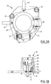
- each magnetic clamp assembly 32 comprises a cylindrical sleeve 34, having an axially disposed bore.
- the cylindrical sleeve 34 is made from annealed super invar which has a thermal coefficient of expansion better than two orders of magnitude below that of steel.
- An actuator 36 having a circular base and a shaft extending vertically downward, is disposed within the cylindrical sleeve 34.
- a permanent magnet 38 is disposed above the actuator 36, within the magnetic clamp assembly 32. The permanent magnet 38 is secured to the actuator 36 base by a pin, dowel, epoxy, or other known means for securing the like.
- a magnetic shunt 40 is fixed within the magnetic clamp assembly 32, above the permanent magnet 38.
- the magnetic shunt 40 consists of opposing pole pieces 42 joined by a joint member 43 formed of a non-magnetic material. Further, the top of the magnetic shunt 40 is disposed within the magnetic clamp assembly 32 such that the top of the magnetic shunt 40 is slightly below the top of the cylindrical sleeve 34.
- a flux blocking shield 35 is interposed between the cylindrical sleeve 34 and the permanent magnet 38.
- the cylindrical sleeve 34 is made from a material having a low thermal coefficient However, the material is also one which is magnetically conductive. As such, without the flux blocking shield 35, the magnetic flux in the magnetic clamp 32 in the actuated state would conduct through the cylindrical sleeve 34, instead of being forced over the magnetic shunt 40, and would therefore not clamp.
- a bushing 33 may optionally be interposed between the flux blocking shield 35 and actuator 36/permanent magnet 38 combination in order to serve as a guide for the actuator 36, permanent magnet 38 combination within the magnetic clamp assembly 32.
- the magnetic clamp assembly 32 is secured to the carriage base plate 31 by a pin, dowel, epoxy, or similar means for securing.
- a screw 39 is used to secure the cylindrical sleeve 34 to the carriage base plate 31.
- the actuator 36 shaft in the magnetic clamp assembly 32 extends through an aperture in the carriage base plate 31 is fastened to the carriage base plate 31 by a gear 37 or similar means for rotatably engaging the actuator 36/permanent magnet 38 combination within the magnetic clamp assembly 32.
- Each gear 37 is mechanically connected to the belt 44 (Fig. 3A) and magnet actuating motor 42 (Fig. 3A), the combination providing a means for rotatably engaging each clamp assembly 32 for releasably clamping the sample carriage 28 in its thermal and vibrational stability configuration.
- a z axis is defined as the longitudinal axis running through the scanning probe 20 and probe tip 22.
- the sample carriage 28 carrying a sample to be scanned is initially positioned by moving the coarse positioner 18, in an x y plane, to a location where the scanning probe 22 is above the area to be scanned.
- the x y plane thus being defined as a plane perpendicular to the z axis.
- an air actuator (not shown), interposed between the sample carriage 28 and positioner 18, is inflated in order to physically decouple the sample carriage 28 from the positioner 18 and to bias the sample carriage 28 against the bottom of the bridge plate 14 (Fig. 2).
- the air actuator serves to decouple the sample carriage 28 from the positioner 18 and move the sample carriage 28 in a vertical (z) direction, without changing the (x,y) position of the sample relative to the probe tip 22.
- the sample carriage 28 is then releasably coupled to the bridge plate 14 by engaging the magnet actuation motor 42, belt 44, and gear 37 at the lower end of the clamp assembly 32.
- the air actuator is deflated in order to completely decouple the sample carriage 28 from the major body of the scanning probe microscope.
- the carriage assembly 28 is thus physically decoupled from the coarse positioner 18 (and hence from the major body of the scanning probe microscope) and releasably clamped to the bridge plate 14 by engaging the magnetic clamp assemblies 32.
- the scanning probe microscope is configured in the thermal and vibrational stability configuration.
- the positioning motor 46 and counter pressure spring 48 combination serve to further position the sample in a fine positioning step. That is, once decoupled from the major body of the scanning probe microscope and releasably coupled to the bridge plate 14, the sample is further positioned by reciprocal forces between a corresponding positioning motor 46 and a counter pressure spring 48.
- the carriage base plate 30 is further adjusted in an fine positioning step. Having completed both coarse and fine positioning the scanning probe microscope is available for a scanning procedure or technique as offered by the scanning probe assembly 20.
- the sample carriage 28, carrying the sample is subsequently repositioned by first recoupling the sample carriage 28 to the coarse positioner 18, by reinflating the air actuator (not shown) and disengaging the magnetic clamps 32. Once recoupled, the sample carriage 28 (and thus the sample to be scanned) is free to be repositioned by the coarse positioner 18, to a subsequent location to be scanned. Upon repositioning, the sample carriage 28 is again decoupled from the coarse positioner 18 and configured in the thermal and vibrational stability configuration.
- the actuator 36/permanent magnet 38 combination in a non engaged mode, is rotated so that the opposing poles (North and South) of the permanent magnet are substantially parallel to the non-magnetic joint 43 of the magnetic shunt 40. In this position, the path of the magnetic flux is as illustrated.
- the nature of the magnetic pole elements 42 are such that they serve to pass or conduct the flow of the magnetic flux path.
- the magnetic flux path passes through the magnetic materials, as shown, and results in a leakage field at the clamp face of 120 gauss in the illustrated embodiment.
- the actuator 36/permanent magnet 38 combination in an engaged mode, is rotated so that the opposing poles (North and South) of the permanent magnet 38 lie on either side of the non-magnetic joint 43 of the magnetic shunt 40. In this position, the path of the magnetic flux is as illustrated.
- the nature of the non-magnetic joint element 43 is such that it serves to impede or block the magnetic flux path.
- the magnetic flux path passes through the magnetic materials, as shown, and results in a peak leakage field at the clamp face of 2.5 kilogauss in the illustrated embodiment.
- the cylindrical sleeve 34 bears against the carriage base plate 30 and bridge plate 14. That is, with the top of the magnetic shunt 40 disposed slightly below the top of the cylindrical sleeve 34, the magnetic shunt is prohibited from physically coming in contact with the bridge plate 14. However, while in the engaged mode, the magnetic flux path to and from the permanent magnet 38 pass through the magnetic shunt 40. Thus, the magnetic shunt 40 is magnetically coupled (along with permanent magnet 38) to the bridge plate 14, without physically contacting the bridge plate 14. In so doing, only the cylindrical sleeve 34 is the only element of the magnetic clamp assembly 32 within the thermal path of the reconfigured system.
Applications Claiming Priority (2)
| Application Number | Priority Date | Filing Date | Title |
|---|---|---|---|
| US973796 | 1992-11-09 | ||
| US07/973,796 US5260577A (en) | 1992-11-09 | 1992-11-09 | Sample carriage for scanning probe microscope |
Publications (2)
| Publication Number | Publication Date |
|---|---|
| EP0597622A1 true EP0597622A1 (de) | 1994-05-18 |
| EP0597622B1 EP0597622B1 (de) | 1997-01-29 |
Family
ID=25521236
Family Applications (1)
| Application Number | Title | Priority Date | Filing Date |
|---|---|---|---|
| EP93308790A Expired - Lifetime EP0597622B1 (de) | 1992-11-09 | 1993-11-03 | Probenträgervorrichtung für ein Rastermikroskop |
Country Status (6)
| Country | Link |
|---|---|
| US (1) | US5260577A (de) |
| EP (1) | EP0597622B1 (de) |
| JP (1) | JP2625636B2 (de) |
| AT (1) | ATE148558T1 (de) |
| CA (1) | CA2107048C (de) |
| DE (1) | DE69307833T2 (de) |
Families Citing this family (10)
| Publication number | Priority date | Publication date | Assignee | Title |
|---|---|---|---|---|
| US5410910A (en) * | 1993-12-22 | 1995-05-02 | University Of Virginia Patent Foundation | Cryogenic atomic force microscope |
| US5483064A (en) * | 1994-01-21 | 1996-01-09 | Wyko Corporation | Positioning mechanism and method for providing coaxial alignment of a probe and a scanning means in scanning tunneling and scanning force microscopy |
| US5831181A (en) * | 1995-09-29 | 1998-11-03 | The Regents Of The University Of California | Automated tool for precision machining and imaging |
| US5821545A (en) * | 1995-11-07 | 1998-10-13 | Molecular Imaging Corporation | Heated stage for a scanning probe microscope |
| US5654546A (en) * | 1995-11-07 | 1997-08-05 | Molecular Imaging Corporation | Variable temperature scanning probe microscope based on a peltier device |
| AU2002222237A1 (en) * | 2000-12-15 | 2002-06-24 | The Technology Partnership Plc | Optical scanning system apparatus |
| CN100489491C (zh) * | 2005-11-17 | 2009-05-20 | 钢铁研究总院 | 金属原位分析仪悬浮式扫描方法及样品夹具 |
| GB0602083D0 (en) | 2006-02-02 | 2006-03-15 | Smartdrive Technology Ltd | Microscopes |
| AT519344B1 (de) | 2016-10-18 | 2019-11-15 | Anton Paar Gmbh | Definiert schaltbare magnetische Haltevorrichtung |
| US10867782B2 (en) * | 2019-01-10 | 2020-12-15 | Shimadzij Corporation | Time-of-flight mass spectrometer |
Citations (8)
| Publication number | Priority date | Publication date | Assignee | Title |
|---|---|---|---|---|
| GB842495A (en) * | 1958-01-18 | 1960-07-27 | Darwins Ltd | Improvements in or relating to magnetic blocks and workholders |
| GB1123250A (en) * | 1966-07-28 | 1968-08-14 | Burndy Corp | Improvements in or relating to supporting platform assemblies |
| US4908519A (en) * | 1988-10-11 | 1990-03-13 | The Board Of Thustees Of The Leland Stanford Jr. University | Loading mechanism and support structure having improved vibration damping useful in scanning tunneling microscopy |
| EP0373742A2 (de) * | 1988-12-13 | 1990-06-20 | Mitsubishi Denki Kabushiki Kaisha | Tunneleinheit und Rasterkopf für ein Tunnelrastermikroskop |
| EP0388023A2 (de) * | 1989-03-13 | 1990-09-19 | The Regents Of The University Of California | Atomisches Kraftmikroskop mit nach Wahl auswechselbarer Flüssigkeitszelle |
| EP0421355A2 (de) * | 1989-10-02 | 1991-04-10 | Olympus Optical Co., Ltd. | Raster-Tunnel-Mikroskop |
| US5103095A (en) * | 1990-05-23 | 1992-04-07 | Digital Instruments, Inc. | Scanning probe microscope employing adjustable tilt and unitary head |
| JPH04179043A (ja) * | 1990-11-13 | 1992-06-25 | Matsushita Electric Ind Co Ltd | 位置決め装置 |
Family Cites Families (8)
| Publication number | Priority date | Publication date | Assignee | Title |
|---|---|---|---|---|
| GB1052542A (de) * | 1964-01-21 | |||
| JPS5918182Y2 (ja) * | 1979-02-02 | 1984-05-26 | 「国」華工業株式会社 | 磁石の反発力を利用した磁気スプリング |
| JPS57169212A (en) * | 1981-04-13 | 1982-10-18 | Kokka Kogyo Kk | Vibration suppressing device |
| US4560880A (en) * | 1983-09-19 | 1985-12-24 | Varian Associates, Inc. | Apparatus for positioning a workpiece in a localized vacuum processing system |
| EP0189498B1 (de) * | 1985-01-29 | 1989-05-03 | International Business Machines Corporation | Feldemissions-Auger-Rasterelektronenmikroskop |
| JP2896794B2 (ja) * | 1988-09-30 | 1999-05-31 | キヤノン株式会社 | 走査型トンネル電流検出装置,走査型トンネル顕微鏡,及び記録再生装置 |
| JP2501897B2 (ja) * | 1988-12-13 | 1996-05-29 | 三菱電機株式会社 | 走査型トンネル顕微鏡のトンネル・ユニット及びスキャン・ヘッド |
| US5041783A (en) * | 1989-02-13 | 1991-08-20 | Olympus Optical Co., Ltd. | Probe unit for an atomic probe microscope |
-
1992
- 1992-11-09 US US07/973,796 patent/US5260577A/en not_active Expired - Lifetime
-
1993
- 1993-09-27 CA CA002107048A patent/CA2107048C/en not_active Expired - Fee Related
- 1993-10-25 JP JP5265966A patent/JP2625636B2/ja not_active Expired - Fee Related
- 1993-11-03 AT AT93308790T patent/ATE148558T1/de not_active IP Right Cessation
- 1993-11-03 DE DE69307833T patent/DE69307833T2/de not_active Expired - Fee Related
- 1993-11-03 EP EP93308790A patent/EP0597622B1/de not_active Expired - Lifetime
Patent Citations (8)
| Publication number | Priority date | Publication date | Assignee | Title |
|---|---|---|---|---|
| GB842495A (en) * | 1958-01-18 | 1960-07-27 | Darwins Ltd | Improvements in or relating to magnetic blocks and workholders |
| GB1123250A (en) * | 1966-07-28 | 1968-08-14 | Burndy Corp | Improvements in or relating to supporting platform assemblies |
| US4908519A (en) * | 1988-10-11 | 1990-03-13 | The Board Of Thustees Of The Leland Stanford Jr. University | Loading mechanism and support structure having improved vibration damping useful in scanning tunneling microscopy |
| EP0373742A2 (de) * | 1988-12-13 | 1990-06-20 | Mitsubishi Denki Kabushiki Kaisha | Tunneleinheit und Rasterkopf für ein Tunnelrastermikroskop |
| EP0388023A2 (de) * | 1989-03-13 | 1990-09-19 | The Regents Of The University Of California | Atomisches Kraftmikroskop mit nach Wahl auswechselbarer Flüssigkeitszelle |
| EP0421355A2 (de) * | 1989-10-02 | 1991-04-10 | Olympus Optical Co., Ltd. | Raster-Tunnel-Mikroskop |
| US5103095A (en) * | 1990-05-23 | 1992-04-07 | Digital Instruments, Inc. | Scanning probe microscope employing adjustable tilt and unitary head |
| JPH04179043A (ja) * | 1990-11-13 | 1992-06-25 | Matsushita Electric Ind Co Ltd | 位置決め装置 |
Non-Patent Citations (1)
| Title |
|---|
| PATENT ABSTRACTS OF JAPAN vol. 016, no. 488 (E - 1277) 9 October 1992 (1992-10-09) * |
Also Published As
| Publication number | Publication date |
|---|---|
| US5260577A (en) | 1993-11-09 |
| ATE148558T1 (de) | 1997-02-15 |
| CA2107048A1 (en) | 1994-05-10 |
| EP0597622B1 (de) | 1997-01-29 |
| JP2625636B2 (ja) | 1997-07-02 |
| JPH06207807A (ja) | 1994-07-26 |
| CA2107048C (en) | 1998-08-11 |
| DE69307833D1 (de) | 1997-03-13 |
| DE69307833T2 (de) | 1997-07-24 |
Similar Documents
| Publication | Publication Date | Title |
|---|---|---|
| US4871938A (en) | Positioning device for a scanning tunneling microscope | |
| Renner et al. | A vertical piezoelectric inertial slider | |
| US5296704A (en) | Scanning tunneling microscope | |
| JP3013858B2 (ja) | 原子的分解能を持った微細位置決め装置 | |
| EP0597622B1 (de) | Probenträgervorrichtung für ein Rastermikroskop | |
| US20040069944A1 (en) | Balanced momentum probe holder | |
| JP2598851B2 (ja) | 位置決め装置 | |
| JPH02298908A (ja) | ミラーのアライメント及びダンピング装置 | |
| US4841148A (en) | Variable temperature scanning tunneling microscope | |
| US6603239B1 (en) | Micromanipulator with piezoelectric movement elements | |
| Brockenbrough et al. | Inertial tip translator for a scanning tunneling microscope | |
| US6078044A (en) | Probe scanning apparatus | |
| US5635836A (en) | Mechanical apparatus with rod, pivot, and translation means for positioning a sample for use with a scanning microscope | |
| Fu et al. | Long‐range scanning for scanning tunneling microscopy | |
| US5423514A (en) | Alignment assembly for aligning a spring element with a laser beam in a probe microscope | |
| US6377066B1 (en) | Method and apparatus for sub-micron imaging and probing on probe station | |
| JP3060527B2 (ja) | 位置決め装置 | |
| JP2937558B2 (ja) | 位置決め装置 | |
| Fischer et al. | Precision fiducialization of transport components | |
| JPH02297003A (ja) | 検出部位置決機構、圧電素子微動機構およびこれらを用いた走査型トンネル顕微鏡 | |
| La Comb Jr et al. | Piezodriven scanner for cryogenic applications | |
| Holmes et al. | Magnetically-suspended stage for accurate positioning of large samples in scanned probe microscopy | |
| Yasutake et al. | Scanning tunneling microscope combined with optical microscope for large sample measurement | |
| Chetwynd | Linear translation mechanisms for nanotechnology applications | |
| JPH09304401A (ja) | プローブ走査装置 |
Legal Events
| Date | Code | Title | Description |
|---|---|---|---|
| PUAI | Public reference made under article 153(3) epc to a published international application that has entered the european phase |
Free format text: ORIGINAL CODE: 0009012 |
|
| AK | Designated contracting states |
Kind code of ref document: A1 Designated state(s): AT BE CH DE ES FR GB IT LI NL SE |
|
| 17P | Request for examination filed |
Effective date: 19940927 |
|
| GRAG | Despatch of communication of intention to grant |
Free format text: ORIGINAL CODE: EPIDOS AGRA |
|
| 17Q | First examination report despatched |
Effective date: 19960306 |
|
| GRAH | Despatch of communication of intention to grant a patent |
Free format text: ORIGINAL CODE: EPIDOS IGRA |
|
| GRAH | Despatch of communication of intention to grant a patent |
Free format text: ORIGINAL CODE: EPIDOS IGRA |
|
| GRAA | (expected) grant |
Free format text: ORIGINAL CODE: 0009210 |
|
| AK | Designated contracting states |
Kind code of ref document: B1 Designated state(s): AT BE CH DE ES FR GB IT LI NL SE |
|
| PG25 | Lapsed in a contracting state [announced via postgrant information from national office to epo] |
Ref country code: NL Free format text: LAPSE BECAUSE OF FAILURE TO SUBMIT A TRANSLATION OF THE DESCRIPTION OR TO PAY THE FEE WITHIN THE PRESCRIBED TIME-LIMIT Effective date: 19970129 Ref country code: FR Free format text: THE PATENT HAS BEEN ANNULLED BY A DECISION OF A NATIONAL AUTHORITY Effective date: 19970129 Ref country code: ES Free format text: THE PATENT HAS BEEN ANNULLED BY A DECISION OF A NATIONAL AUTHORITY Effective date: 19970129 Ref country code: BE Effective date: 19970129 Ref country code: AT Effective date: 19970129 |
|
| REF | Corresponds to: |
Ref document number: 148558 Country of ref document: AT Date of ref document: 19970215 Kind code of ref document: T |
|
| REG | Reference to a national code |
Ref country code: CH Ref legal event code: NV Representative=s name: CARL O. BARTH C/O IBM CORPORATION ZURICH INTELLECT Ref country code: CH Ref legal event code: EP |
|
| REF | Corresponds to: |
Ref document number: 69307833 Country of ref document: DE Date of ref document: 19970313 |
|
| ITF | It: translation for a ep patent filed |
Owner name: 0508;25MIFIBM - DR. ALFREDO BRAVI |
|
| PG25 | Lapsed in a contracting state [announced via postgrant information from national office to epo] |
Ref country code: SE Effective date: 19970429 |
|
| ET | Fr: translation filed | ||
| NLV1 | Nl: lapsed or annulled due to failure to fulfill the requirements of art. 29p and 29m of the patents act | ||
| PLBE | No opposition filed within time limit |
Free format text: ORIGINAL CODE: 0009261 |
|
| STAA | Information on the status of an ep patent application or granted ep patent |
Free format text: STATUS: NO OPPOSITION FILED WITHIN TIME LIMIT |
|
| 26N | No opposition filed | ||
| REG | Reference to a national code |
Ref country code: FR Ref legal event code: ST |
|
| PGFP | Annual fee paid to national office [announced via postgrant information from national office to epo] |
Ref country code: CH Payment date: 20010227 Year of fee payment: 8 |
|
| PGFP | Annual fee paid to national office [announced via postgrant information from national office to epo] |
Ref country code: GB Payment date: 20011105 Year of fee payment: 9 |
|
| PG25 | Lapsed in a contracting state [announced via postgrant information from national office to epo] |
Ref country code: LI Free format text: LAPSE BECAUSE OF NON-PAYMENT OF DUE FEES Effective date: 20011130 Ref country code: CH Free format text: LAPSE BECAUSE OF NON-PAYMENT OF DUE FEES Effective date: 20011130 |
|
| REG | Reference to a national code |
Ref country code: GB Ref legal event code: IF02 |
|
| REG | Reference to a national code |
Ref country code: CH Ref legal event code: PL |
|
| PG25 | Lapsed in a contracting state [announced via postgrant information from national office to epo] |
Ref country code: GB Free format text: LAPSE BECAUSE OF NON-PAYMENT OF DUE FEES Effective date: 20021103 |
|
| GBPC | Gb: european patent ceased through non-payment of renewal fee | ||
| PG25 | Lapsed in a contracting state [announced via postgrant information from national office to epo] |
Ref country code: IT Free format text: LAPSE BECAUSE OF NON-PAYMENT OF DUE FEES Effective date: 20051103 |
|
| PGFP | Annual fee paid to national office [announced via postgrant information from national office to epo] |
Ref country code: DE Payment date: 20081126 Year of fee payment: 16 |
|
| PG25 | Lapsed in a contracting state [announced via postgrant information from national office to epo] |
Ref country code: DE Free format text: LAPSE BECAUSE OF NON-PAYMENT OF DUE FEES Effective date: 20100601 |
|
| REG | Reference to a national code |
Ref country code: DE Ref legal event code: R081 Ref document number: 69307833 Country of ref document: DE Owner name: GLOBALFOUNDRIES INC., KY Free format text: FORMER OWNER: INTERNATIONAL BUSINESS MACHINES CORPORATION, ARMONK, NY, US Ref country code: DE Ref legal event code: R082 Ref document number: 69307833 Country of ref document: DE Representative=s name: RICHARDT PATENTANWAELTE PARTG MBB, DE Ref country code: DE Ref legal event code: R081 Ref document number: 69307833 Country of ref document: DE Owner name: GLOBALFOUNDRIES INC., KY Free format text: FORMER OWNER: INTERNATIONAL BUSINESS MACHINES CORPORATION, ARMONK, N.Y., US |
|
| REG | Reference to a national code |
Ref country code: DE Ref legal event code: R082 Ref document number: 69307833 Country of ref document: DE Representative=s name: RICHARDT PATENTANWAELTE PARTG MBB, DE Ref country code: DE Ref legal event code: R081 Ref document number: 69307833 Country of ref document: DE Owner name: GLOBALFOUNDRIES INC., KY Free format text: FORMER OWNER: GLOBALFOUNDRIES US 2 LLC (N.D.GES.DES STAATES DELAWARE), HOPEWELL JUNCTION, N.Y., US |
|
| REG | Reference to a national code |
Ref country code: FR Ref legal event code: TP Owner name: GLOBALFOUNDRIES INC., GB Effective date: 20160829 |