EP0597352A2 - Elektronisches Zündsystem für innere Brennkraftmaschinen mit differenziertem Lastversorgungssystem - Google Patents
Elektronisches Zündsystem für innere Brennkraftmaschinen mit differenziertem Lastversorgungssystem Download PDFInfo
- Publication number
- EP0597352A2 EP0597352A2 EP93117720A EP93117720A EP0597352A2 EP 0597352 A2 EP0597352 A2 EP 0597352A2 EP 93117720 A EP93117720 A EP 93117720A EP 93117720 A EP93117720 A EP 93117720A EP 0597352 A2 EP0597352 A2 EP 0597352A2
- Authority
- EP
- European Patent Office
- Prior art keywords
- voltage
- magneto generator
- ignition
- capacitor
- switch means
- Prior art date
- Legal status (The legal status is an assumption and is not a legal conclusion. Google has not performed a legal analysis and makes no representation as to the accuracy of the status listed.)
- Withdrawn
Links
Images
Classifications
-
- F—MECHANICAL ENGINEERING; LIGHTING; HEATING; WEAPONS; BLASTING
- F02—COMBUSTION ENGINES; HOT-GAS OR COMBUSTION-PRODUCT ENGINE PLANTS
- F02P—IGNITION, OTHER THAN COMPRESSION IGNITION, FOR INTERNAL-COMBUSTION ENGINES; TESTING OF IGNITION TIMING IN COMPRESSION-IGNITION ENGINES
- F02P1/00—Installations having electric ignition energy generated by magneto- or dynamo- electric generators without subsequent storage
- F02P1/08—Layout of circuits
- F02P1/086—Layout of circuits for generating sparks by discharging a capacitor into a coil circuit
-
- F—MECHANICAL ENGINEERING; LIGHTING; HEATING; WEAPONS; BLASTING
- F02—COMBUSTION ENGINES; HOT-GAS OR COMBUSTION-PRODUCT ENGINE PLANTS
- F02P—IGNITION, OTHER THAN COMPRESSION IGNITION, FOR INTERNAL-COMBUSTION ENGINES; TESTING OF IGNITION TIMING IN COMPRESSION-IGNITION ENGINES
- F02P3/00—Other installations
- F02P3/06—Other installations having capacitive energy storage
- F02P3/08—Layout of circuits
- F02P3/0876—Layout of circuits the storage capacitor being charged by means of an energy converter (DC-DC converter) or of an intermediate storage inductance
- F02P3/0884—Closing the discharge circuit of the storage capacitor with semiconductor devices
-
- G—PHYSICS
- G05—CONTROLLING; REGULATING
- G05F—SYSTEMS FOR REGULATING ELECTRIC OR MAGNETIC VARIABLES
- G05F1/00—Automatic systems in which deviations of an electric quantity from one or more predetermined values are detected at the output of the system and fed back to a device within the system to restore the detected quantity to its predetermined value or values, i.e. retroactive systems
- G05F1/10—Regulating voltage or current
- G05F1/46—Regulating voltage or current wherein the variable actually regulated by the final control device is DC
- G05F1/62—Regulating voltage or current wherein the variable actually regulated by the final control device is DC using bucking or boosting DC sources
-
- H—ELECTRICITY
- H02—GENERATION; CONVERSION OR DISTRIBUTION OF ELECTRIC POWER
- H02J—ELECTRIC POWER NETWORKS; CIRCUIT ARRANGEMENTS OR SYSTEMS FOR SUPPLYING OR DISTRIBUTING ELECTRIC POWER; SYSTEMS FOR STORING ELECTRIC ENERGY
- H02J7/00—Circuit arrangements for charging or discharging batteries or for supplying loads from batteries
- H02J7/14—Circuit arrangements for charging or discharging batteries or for supplying loads from batteries for charging batteries from dynamo-electric generators driven at varying speed, e.g. on vehicle
- H02J7/1438—Circuit arrangements for charging or discharging batteries or for supplying loads from batteries for charging batteries from dynamo-electric generators driven at varying speed, e.g. on vehicle in combination with power supplies for loads other than batteries
Definitions
- the present invention relates to an electronic ignition system of capacitor discharge type for internal combustion engines, intended to be used especially although not exclusively for motorcycles and the like, and more particularly relates to an ignition apparatus comprising an electronic control system providing a differentiated power supply to electrical loads and to a capacitor of the ignition system while allowing a rational use of the electric power available at the output of the magneto generator.
- various ignition control systems which provide for the use of an electric battery as a primary power source, or the use of a magneto generator, such as an alternator provided with different windings for supplying various electric loads of the vehicle, such as the engine ignition circuit and other service load circuits.
- US-A- 3.312.860 and US-A- 4.323.216 are examples of the first ignition systems which use an electric battery as a primary power source.
- Systems of this kind even if controllable by a microprocessor, necessarily require the use of suitable voltage boostering devices for supplying the electric energy from the battery, normally available at a voltage of 12 Volts, to a higher value voltage, for example a few hundred Volts required for the successful ignition operation.
- US-A- 3.242.420, US-A- 3.933.139 and US-A-4.565.179 are representative of ignition system of the second type which make use of a magneto generator as a primary power source.
- different windings have to be provided in the generator for supplying the power to the ignition circuit, as well for picking up synchronism signals and for supplying a low voltage power to other electric loads of the vehicle or other appliances provided with a similar ignition system.
- the ignition systems which use an electric generator as a primary power source have the disadvantage of being unreliable in that the winding for supplying the ignition circuit normally consists of a high number of turns, in the order of a few thousands, made with thin copper wire, to supply the voltage required for charging the capacitor. These windings, in addition to being difficult to manufacture, also require special techniques such as for example the use of short-circuit turns for limiting the maximum value of the voltage generated to avoid excessive heating. Furthermore the known ignition systems usually require different windings to operate at low-speed and high-speed of the magneto generator.
- US-A-4.478.200 and US-A- 4.537.174 suggest the use of an electronic ignition device including a magneto generator having substantially a single generating coil and change over circuit to change over the supply of electrical power from the capacitor of the ignition circuit, to an electrical load circuit.
- the energy for the ignition and any other load is obtained with a high induced voltage produced upon a rapid interruption of a short-circuit current flowing in the generating coil once a half cycle only; a constant voltage supply for the ignition system is therefore operated by the output current of the magneto generator preceding the interruption of the short-circuit.
- a regulator transfers the excess output of the magneto generator to a battery or other electrical load in response to an over voltage.
- the charging voltage for ignition capacitor is within the range between 200V and 300V while the voltage required for the electrical load of a motorvehicle is of about 6V or 12V. Therefore, according to US-A- 4.478.200 an additional step up transformer is required to provide the required high voltage for charging the capacitor. Owing to the necessity of said transformer to work at low running of the engine also it will require windings having a relevant number of turns resulting in an heavy and cumbersome construction; furthermore the use of a step-up transformer does not resolve the problem inherent to bell curve for the charging voltage of the ignition capacitor thus resulting in low operational level.
- a further object of the present invention is to provide an ignition system of the kind referred to above, which is both simply to manufacture and relatively less expensive, providing at the same time an appropriate control of the load and ignition supply voltages.
- a single source of power such as a magneto generator having a single generating coil for supplying both the ignition circuit of the engine and other service load circuits of the vehicle or equipment on which it is installed, providing a voltage boostering device comprising the inductance of the single coil of the generator in combination with electronic switches controlled by a process logic unit which provide for the separate supply of the ignition circuit, and service loads respectively, at different times on the basis of control signals provided by sensing means continuously detecting the operative conditions of the engine.
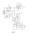
- the ignition system for an internal combustion engine substantially comprises an electric AC generator 10, hereinafter referred to as magneto generator having substantially a single rotor winding 11 for supplying the electric power both to the module of an ignition circuit 12 of an internal combustion engine, and to other electric load circuit 13 of a motor vehicle, or any other appliance on which this ignition system is used, and which may comprise for example an auxiliary battery 14, the lights 15 of the vehicle or another load 15' to be supplied.
- an electric AC generator 10 hereinafter referred to as magneto generator having substantially a single rotor winding 11 for supplying the electric power both to the module of an ignition circuit 12 of an internal combustion engine, and to other electric load circuit 13 of a motor vehicle, or any other appliance on which this ignition system is used, and which may comprise for example an auxiliary battery 14, the lights 15 of the vehicle or another load 15' to be supplied.
- a process logic unit 16 such as a microprocessor, or a digital control device having data inlet ports which receive informations on working parameters S1, S2, Sn corresponding to operative conditions of the engine, and which processes said data to supply appropriate control signals on one or more outputs 20, 21, 22, 23, as shown.
- a process logic unit 16 such as a microprocessor, or a digital control device having data inlet ports which receive informations on working parameters S1, S2, Sn corresponding to operative conditions of the engine, and which processes said data to supply appropriate control signals on one or more outputs 20, 21, 22, 23, as shown.
- reference numeral 11 schematically denotes the synchronous inductance of the single coil of the magneto generator.
- the ignition circuit of the module 12 may be of any desired type; in general it comprises a voltage step-up transformer T having secondary winding or coil connected to the electric spark-plug of the engine, as well as a primary winding or coil connected to a ignition capacitor C supplied by the electrical power generated by the coil 11 of the magneto generator 10, via a connection path 18 comprising an electronic switch T2 for changing over the power provided by the magneto generator 10 and to control the charge voltage of the capacitor C; switch T2 has its control inlet connected to the output 22 of the logic unit 16; T2 may be any electronic switch device of the type known, such as a transistor, a SCR or a MOS switch, which can be controlled by the process logic unit 16, as shown. Correspondingly, the charging and discharging of the capacitor C of the ignition circuit can be usually controlled by a second electronic switch in the same circuit, for example an SCR, whose control gate is connected to an output 20 of the logic unit 16.
- Reference 19 in Fig. 1 denotes moreover a connection between the positive terminal of the capacitor C and a corresponding data inlet of the process logic unit 16 which can in this way receive informations on the charge voltage values of the capacitor C.
- T1 in Fig. 1 optionally denotes an auxiliary ON/OFF voltage regulator, connected in series between the coil 11 of the generator and the load circuit 13, for controlling the supply voltage to the loads during operation; the voltage regulator T1 may be of any desired type and is functionally comparable to an electronic switch device whose control gate is connected to a control signal output 21 of the process logic unit 16.
- a further voltage regulator comprising an electronic switch device T3 branched-off by the connection between the coil 11 and the electronic switch T2 for controlling the charge voltage of the capacitor C, said switch T3 defining a short-circuiting means for the coil 11 having a control inlet in turn connected to a control output 23 of the process logic unit 16.
- the electronic switch T3 is therefore connected to T2 and to the stator winding 11 of the magneto generator to perform a dual function that is a boostering action to increase the charge voltage fed to the capacitor C, and rapidly actuable ON/OFF voltage regulating actions during positive one-half cycle outputs of magneto generator 10 for the supply voltages of the capacitor C and service load circuit 13. It is however clear that the various electronic components of the circuit shown may be replaced by other elements or by equivalent circuitry solutions, without thereby departing from the inventive principal of the present invention.
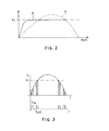
- the process logic unit 16 bring out of operation of the voltage regulator T1 preventing the supply of load circuit 13, while bring into operation the switch T2, allowing to supply the power to the ignition circuit 12. If the voltage provided by the magneto generator 10 is lower than the voltage V1 required to charge the ignition capacitor C, then the logic unit 16, as indicated schematically in the graph in Fig. 3, repeatedly trigger on and off the electronic switch T3 of the voltage booster comprising the same switch T3 and the internal inductance of the coil 11 of the magneto generator, with a suitable frequency provided by an appropriate Ton/Toff ratio between the closing time Ton, and opening time Toff in which Ton and Toff are depending on the features of the generator and on the rotational speed of the engine.
- Ton period is inversely proportional to the voltage of the magneto generator; Toff likewise is inversely proportional to the voltage of the ignition capacitor C; while both Ton and Toff are directly proportional to the inductance of coil 11 of the magneto generator.
- Ton and Toff are directly proportional to the inductance of coil 11 of the magneto generator.
- the logic unit 16 When the logic unit 16 detects at its input 19 that the required charge voltage is present on the ignition capacitor C, it commands the switch off of the switches T2 and T3 since the supplying phase for the ignition capacitor C has ended.
- the second operational phase for supplying and controlling the voltage to the loads 13 can begin, in a fully independent and differentiated manner from the previous phase.
- the voltage at the loads 13 can be controlled in two different or combinable ways:
- Second regulation mode the voltage to the loads 13 can be regulated also by a second mode of operation, through a branched off regulation circuit, comprising the switch T3 by short-circuiting the generator 10 towards earth, when the voltage on the loads 13 tends to increase, or vice versa to switch on T3, maintaining T1 closed and T2 opened.
- the system for regulating the voltages at the ignition circuit 12 and at the loads 13, is therefore controlled by the process logic unit 16, by means of T1, T2 and T3 maintaining the charging phases of the ignition capacitor C and the supplying phases of the loads 13 constantly separate in time, so that they occur in a manner fully differentiated one from the other.
- the logic unit 16 on the basis of the information received by the various sensors S1, S2, Sn, at the appropriate time sends a command to discharge the capacitor C of the ignition module 12, and if necessary also to other actuators connected thereto, in this way controlling the whole ignition system in a manner co-related to running of the engine.
- the charge voltage of the capacitor C can be maintained at a constant value, as shown by the curve B in Fig. 2, in relation to a bell curve A of the same voltage according to traditional ignition systems.
Landscapes
- Engineering & Computer Science (AREA)
- Chemical & Material Sciences (AREA)
- Combustion & Propulsion (AREA)
- Mechanical Engineering (AREA)
- General Engineering & Computer Science (AREA)
- Physics & Mathematics (AREA)
- Electromagnetism (AREA)
- General Physics & Mathematics (AREA)
- Radar, Positioning & Navigation (AREA)
- Automation & Control Theory (AREA)
- Power Engineering (AREA)
- Ignition Installations For Internal Combustion Engines (AREA)
Applications Claiming Priority (2)
| Application Number | Priority Date | Filing Date | Title |
|---|---|---|---|
| ITMI922564 | 1992-11-09 | ||
| ITMI922564A IT1256379B (it) | 1992-11-09 | 1992-11-09 | Impianto elettronico di accensione per motori a scoppio,con sistema di alimentazione dei carichi differenziato |
Publications (2)
| Publication Number | Publication Date |
|---|---|
| EP0597352A2 true EP0597352A2 (de) | 1994-05-18 |
| EP0597352A3 EP0597352A3 (de) | 1995-01-18 |
Family
ID=11364258
Family Applications (1)
| Application Number | Title | Priority Date | Filing Date |
|---|---|---|---|
| EP93117720A Withdrawn EP0597352A3 (de) | 1992-11-09 | 1993-11-02 | Elektronisches Zündsystem für innere Brennkraftmaschinen mit differenziertem Lastversorgungssystem. |
Country Status (2)
| Country | Link |
|---|---|
| EP (1) | EP0597352A3 (de) |
| IT (1) | IT1256379B (de) |
Cited By (5)
| Publication number | Priority date | Publication date | Assignee | Title |
|---|---|---|---|---|
| EP0646723A1 (de) * | 1993-10-05 | 1995-04-05 | Honda Giken Kogyo Kabushiki Kaisha | Vorrichtung zur Benützung in einem Kraftfahrzeug ohne Batterie zur Verminderung und Steuerung von Belastungen, sowie elektrische Komponenten, während des Anlassens |
| EP0684381A3 (de) * | 1994-05-26 | 1996-04-10 | Ducati Energia Spa | Selektives Stromversorgungsgerät für elektrische Verbraucher und Zündsystem von inneren Brennkraftmaschinen in Motorfahrzeugen. |
| EP0883224A1 (de) * | 1997-06-03 | 1998-12-09 | MAGNETI MARELLI S.p.A. | Stromversorgungsystem für elektrische Lasten in einem Fahrzeug mit Verbrennungsmotor |
| EP0936720A3 (de) * | 1998-02-12 | 2001-11-28 | Mitsuba Corporation Co., Ltd. | Lampbeleuchtungs- und Batterieladesteuerungssystem für ein Fahrzeug |
| WO2009099388A1 (en) * | 2008-02-07 | 2009-08-13 | Sem Aktiebolag | A system for energy support in a cdi system |
Family Cites Families (9)
| Publication number | Priority date | Publication date | Assignee | Title |
|---|---|---|---|---|
| CA999642A (en) * | 1973-01-10 | 1976-11-09 | Eltra Corporation | Small engine ignition system with spark advance |
| US3911889A (en) * | 1973-03-29 | 1975-10-14 | Nippon Denso Co | Capacitor discharge type contactless ignition system for internal combustion engines |
| GB1501621A (en) * | 1975-02-06 | 1978-02-22 | Lucas Industries Ltd | Spark ignition systems for internal combustion engines |
| JPS58117357A (ja) * | 1981-12-29 | 1983-07-12 | Kioritz Corp | 補器用電力取り出し可能な内燃機関電子点火装置 |
| US4537174A (en) * | 1982-04-02 | 1985-08-27 | Nippondenso Co., Ltd. | Output supply control apparatus for internal combustion engine magneto generator |
| JPS58211563A (ja) * | 1982-06-02 | 1983-12-09 | Nippon Denso Co Ltd | 内燃機関用無接点点火装置 |
| JPS6357871A (ja) * | 1986-08-28 | 1988-03-12 | Nippon Denso Co Ltd | 内燃機関用点火装置 |
| JPH0192578A (ja) * | 1987-10-05 | 1989-04-11 | Nippon Denso Co Ltd | 内燃機関用無接点点火装置 |
| US5049786A (en) * | 1990-08-09 | 1991-09-17 | Coen Company, Inc. | High energy ignitor power circuit |
-
1992
- 1992-11-09 IT ITMI922564A patent/IT1256379B/it active IP Right Grant
-
1993
- 1993-11-02 EP EP93117720A patent/EP0597352A3/de not_active Withdrawn
Cited By (12)
| Publication number | Priority date | Publication date | Assignee | Title |
|---|---|---|---|---|
| EP0646723A1 (de) * | 1993-10-05 | 1995-04-05 | Honda Giken Kogyo Kabushiki Kaisha | Vorrichtung zur Benützung in einem Kraftfahrzeug ohne Batterie zur Verminderung und Steuerung von Belastungen, sowie elektrische Komponenten, während des Anlassens |
| EP0684381A3 (de) * | 1994-05-26 | 1996-04-10 | Ducati Energia Spa | Selektives Stromversorgungsgerät für elektrische Verbraucher und Zündsystem von inneren Brennkraftmaschinen in Motorfahrzeugen. |
| US5630404A (en) * | 1994-05-26 | 1997-05-20 | Ducati Energia S.P.A. | Selectively power feeding device for electrical loads and the ignition circuit of internal combustion engines, in motor-vehicles |
| CN1049954C (zh) * | 1994-05-26 | 2000-03-01 | 杜卡提·恩勒基公司 | 给摩托车的电力负载及其内燃机的点火电路选择供电的装置 |
| EP0883224A1 (de) * | 1997-06-03 | 1998-12-09 | MAGNETI MARELLI S.p.A. | Stromversorgungsystem für elektrische Lasten in einem Fahrzeug mit Verbrennungsmotor |
| EP0936720A3 (de) * | 1998-02-12 | 2001-11-28 | Mitsuba Corporation Co., Ltd. | Lampbeleuchtungs- und Batterieladesteuerungssystem für ein Fahrzeug |
| WO2009099388A1 (en) * | 2008-02-07 | 2009-08-13 | Sem Aktiebolag | A system for energy support in a cdi system |
| JP2011511211A (ja) * | 2008-02-07 | 2011-04-07 | セム アクティエボラグ | Cdiシステムにおけるエネルギ支援のためのシステム |
| CN101939534B (zh) * | 2008-02-07 | 2013-03-13 | Sem股份公司 | 用于电容性放电点火系统中的能量支持的系统 |
| RU2480618C2 (ru) * | 2008-02-07 | 2013-04-27 | СЕМ Актиеболаг | Система генерации энергии в системе зажигания емкостным разрядом |
| US8490609B2 (en) | 2008-02-07 | 2013-07-23 | Sem Aktiebolag | System for energy support in a CDI system |
| EP2238340A4 (de) * | 2008-02-07 | 2018-03-14 | SEM Aktiebolag | System zur stromunterstützung in einem cdi-system |
Also Published As
| Publication number | Publication date |
|---|---|
| IT1256379B (it) | 1995-12-04 |
| EP0597352A3 (de) | 1995-01-18 |
| ITMI922564A1 (it) | 1994-05-09 |
| ITMI922564A0 (it) | 1992-11-09 |
Similar Documents
| Publication | Publication Date | Title |
|---|---|---|
| US5418401A (en) | Power supply apparatus for a vehicle having batteries of different voltages which are charged according to alternator speed | |
| US7176658B2 (en) | Controller for permanent magnet alternator | |
| US5323102A (en) | Power source unit for an automotive vehicle | |
| US5214371A (en) | Voltage regulator for variable speed permanent magnet alternators | |
| US4694238A (en) | Dual voltage power supply system for vehicles | |
| KR100220898B1 (ko) | 발전기의 제어장치 및 제어방법과 그것을 응용한 차량용 발전기의 제어장치 및 제어방법 | |
| US4672294A (en) | Dual battery system with improved overvoltage protection | |
| KR100376920B1 (ko) | 차량용 교류발전기의 제어장치 | |
| JP2001298873A (ja) | 車両用電源装置 | |
| KR100515427B1 (ko) | 발전기 제어 방법 | |
| US5642021A (en) | Method and system for controlling an alternator to optimize direct current output | |
| US6335575B1 (en) | Electrical voltage supply system | |
| US6445079B1 (en) | Method and apparatus for controlling an induction machine | |
| JP3627047B2 (ja) | 発電機の出力電圧を制御する電圧制御器 | |
| US6304056B1 (en) | Pulsed charge power delivery circuit for a vehicle having a combined starter/alternator | |
| US4478200A (en) | Electronic ignition system for internal combustion engine capable of supplying electric power to auxiliary unit | |
| KR100426886B1 (ko) | 두 출력 전압을 가진 전압공급장치 | |
| US5723973A (en) | Generating apparatus | |
| EP0597352A2 (de) | Elektronisches Zündsystem für innere Brennkraftmaschinen mit differenziertem Lastversorgungssystem | |
| KR0123543B1 (ko) | 차량용 교류발전기의 전압조정기 | |
| US5630404A (en) | Selectively power feeding device for electrical loads and the ignition circuit of internal combustion engines, in motor-vehicles | |
| GB2350946A (en) | Motor vehicle power supply | |
| KR100216015B1 (ko) | 교류발전기의출력전압제어장치 | |
| US6111393A (en) | Phase-controlled voltage regulation with minimal energy loss | |
| JP3938255B2 (ja) | 多出力バッテリ充電装置 |
Legal Events
| Date | Code | Title | Description |
|---|---|---|---|
| PUAI | Public reference made under article 153(3) epc to a published international application that has entered the european phase |
Free format text: ORIGINAL CODE: 0009012 |
|
| AK | Designated contracting states |
Kind code of ref document: A2 Designated state(s): AT DE ES FR IT SE |
|
| PUAL | Search report despatched |
Free format text: ORIGINAL CODE: 0009013 |
|
| AK | Designated contracting states |
Kind code of ref document: A3 Designated state(s): AT DE ES FR IT SE |
|
| STAA | Information on the status of an ep patent application or granted ep patent |
Free format text: STATUS: THE APPLICATION IS DEEMED TO BE WITHDRAWN |
|
| 18D | Application deemed to be withdrawn |
Effective date: 19950719 |