EP0596332B1 - Device for cleaning large quantities of water from debris - Google Patents
Device for cleaning large quantities of water from debris Download PDFInfo
- Publication number
- EP0596332B1 EP0596332B1 EP93117013A EP93117013A EP0596332B1 EP 0596332 B1 EP0596332 B1 EP 0596332B1 EP 93117013 A EP93117013 A EP 93117013A EP 93117013 A EP93117013 A EP 93117013A EP 0596332 B1 EP0596332 B1 EP 0596332B1
- Authority
- EP
- European Patent Office
- Prior art keywords
- conveyor
- separation area
- water
- takeover
- screenings
- Prior art date
- Legal status (The legal status is an assumption and is not a legal conclusion. Google has not performed a legal analysis and makes no representation as to the accuracy of the status listed.)
- Expired - Lifetime
Links
- XLYOFNOQVPJJNP-UHFFFAOYSA-N water Substances O XLYOFNOQVPJJNP-UHFFFAOYSA-N 0.000 title claims abstract description 45
- 238000004140 cleaning Methods 0.000 title claims abstract description 6
- 238000000926 separation method Methods 0.000 claims description 25
- 230000000149 penetrating effect Effects 0.000 claims description 2
- 238000012216 screening Methods 0.000 description 34
- 230000014759 maintenance of location Effects 0.000 description 3
- 238000010521 absorption reaction Methods 0.000 description 2
- 238000007873 sieving Methods 0.000 description 2
- 235000013361 beverage Nutrition 0.000 description 1
- 230000015572 biosynthetic process Effects 0.000 description 1
- 239000000498 cooling water Substances 0.000 description 1
- 230000001419 dependent effect Effects 0.000 description 1
- 230000008021 deposition Effects 0.000 description 1
- 238000005516 engineering process Methods 0.000 description 1
- 239000007788 liquid Substances 0.000 description 1
- 238000000034 method Methods 0.000 description 1
- 239000010841 municipal wastewater Substances 0.000 description 1
- 239000008213 purified water Substances 0.000 description 1
- 230000000630 rising effect Effects 0.000 description 1
- 239000010865 sewage Substances 0.000 description 1
- 230000001960 triggered effect Effects 0.000 description 1
Images


Classifications
-
- C—CHEMISTRY; METALLURGY
- C02—TREATMENT OF WATER, WASTE WATER, SEWAGE, OR SLUDGE
- C02F—TREATMENT OF WATER, WASTE WATER, SEWAGE, OR SLUDGE
- C02F1/00—Treatment of water, waste water, or sewage
- C02F1/40—Devices for separating or removing fatty or oily substances or similar floating material
-
- E—FIXED CONSTRUCTIONS
- E02—HYDRAULIC ENGINEERING; FOUNDATIONS; SOIL SHIFTING
- E02B—HYDRAULIC ENGINEERING
- E02B8/00—Details of barrages or weirs ; Energy dissipating devices carried by lock or dry-dock gates
- E02B8/02—Sediment base gates; Sand sluices; Structures for retaining arresting waterborne material
- E02B8/023—Arresting devices for waterborne materials
- E02B8/026—Cleaning devices
-
- B—PERFORMING OPERATIONS; TRANSPORTING
- B01—PHYSICAL OR CHEMICAL PROCESSES OR APPARATUS IN GENERAL
- B01D—SEPARATION
- B01D29/00—Filters with filtering elements stationary during filtration, e.g. pressure or suction filters, not covered by groups B01D24/00 - B01D27/00; Filtering elements therefor
- B01D29/01—Filters with filtering elements stationary during filtration, e.g. pressure or suction filters, not covered by groups B01D24/00 - B01D27/00; Filtering elements therefor with flat filtering elements
- B01D29/03—Filters with filtering elements stationary during filtration, e.g. pressure or suction filters, not covered by groups B01D24/00 - B01D27/00; Filtering elements therefor with flat filtering elements self-supporting
- B01D29/035—Filters with filtering elements stationary during filtration, e.g. pressure or suction filters, not covered by groups B01D24/00 - B01D27/00; Filtering elements therefor with flat filtering elements self-supporting with curved filtering elements
-
- B—PERFORMING OPERATIONS; TRANSPORTING
- B01—PHYSICAL OR CHEMICAL PROCESSES OR APPARATUS IN GENERAL
- B01D—SEPARATION
- B01D29/00—Filters with filtering elements stationary during filtration, e.g. pressure or suction filters, not covered by groups B01D24/00 - B01D27/00; Filtering elements therefor
- B01D29/44—Edge filtering elements, i.e. using contiguous impervious surfaces
- B01D29/445—Bar screens
-
- B—PERFORMING OPERATIONS; TRANSPORTING
- B01—PHYSICAL OR CHEMICAL PROCESSES OR APPARATUS IN GENERAL
- B01D—SEPARATION
- B01D29/00—Filters with filtering elements stationary during filtration, e.g. pressure or suction filters, not covered by groups B01D24/00 - B01D27/00; Filtering elements therefor
- B01D29/62—Regenerating the filter material in the filter
- B01D29/64—Regenerating the filter material in the filter by scrapers, brushes, nozzles, or the like, acting on the cake side of the filtering element
- B01D29/6469—Regenerating the filter material in the filter by scrapers, brushes, nozzles, or the like, acting on the cake side of the filtering element scrapers
- B01D29/6476—Regenerating the filter material in the filter by scrapers, brushes, nozzles, or the like, acting on the cake side of the filtering element scrapers with a rotary movement with respect to the filtering element
-
- E—FIXED CONSTRUCTIONS
- E02—HYDRAULIC ENGINEERING; FOUNDATIONS; SOIL SHIFTING
- E02B—HYDRAULIC ENGINEERING
- E02B15/00—Cleaning or keeping clear the surface of open water; Apparatus therefor
- E02B15/04—Devices for cleaning or keeping clear the surface of open water from oil or like floating materials by separating or removing these materials
- E02B15/10—Devices for removing the material from the surface
- E02B15/104—Conveyors; Paddle wheels; Endless belts
-
- C—CHEMISTRY; METALLURGY
- C02—TREATMENT OF WATER, WASTE WATER, SEWAGE, OR SLUDGE
- C02F—TREATMENT OF WATER, WASTE WATER, SEWAGE, OR SLUDGE
- C02F2103/00—Nature of the water, waste water, sewage or sludge to be treated
- C02F2103/007—Contaminated open waterways, rivers, lakes or ponds
Definitions
- the invention relates to a device for cleaning large amounts of water from screenings at overflow edges, with the features specified in the preamble of claim 1.
- a device for cleaning large amounts of water from screenings at overflow edges with the features specified in the preamble of claim 1.
- B. cooling water to be removed in large quantities from a river an overflow edge is usually created and the overflowing water is removed.
- this should be free of screenings up to floating suspended matter.
- the task of sieving large amounts of water arises especially when and after the occurrence of a large rain event, for example a thunderstorm. A considerable amount of water then accumulates in a relatively short time, and the sewage treatment plant is not designed to cope with it.
- Rain retention basins and rain overflow basins are used here to temporarily store the large amount of water and to process it specifically after the end of the rain event. But also such rain retention basins only have a limited absorption capacity, which is rarely exceeded, so that the excess water then accumulated unexplained z. B. is directed into a river. Especially in such thunderstorms and especially after periods of dry weather, the amount of water that comes with it entails a large amount of dirt that needs to be separated.
- a device of the type described above is known from DE-A-40 37 884.
- the separating surface is designed as a piece of a cylinder jacket and is arranged with an axis lying parallel to the overflow edge.
- the separating surface extends over approximately 90 ° of the cylinder jacket, and the axis of the cylinder jacket is provided about the radius of the cylinder jacket lower than the overflow edge, so that the water flowing over the overflow edge approximately at the highest point of the cylinder jacket is fed.
- the separation area is thus limited in terms of area, and there is a risk that after clogging of the separation area, the water will flow over the device unpurified and into an outlet channel which runs across the overflow edge in the direction of flow.
- a transfer unit driven around the axis of the cylinder jacket, is assigned to the separation surface for the removal of the screenings deposited on the separation surface.
- the transfer unit is driven by the overflowing water itself, so that the drive is dependent on the water level above the overflow edge. If the water level is low, there is a risk that the transfer unit will no longer be driven. If the water level is high, there is a risk that the separating area, which is limited in area, will quickly clog and the further water will flow over unpurified.
- the invention has for its object to provide a device of the type described above with which large amounts of water can be reliably cleaned without the risk that the separation surface clogs.
- the separating surface is arranged with its axis approximately at the height of the overflow edge and extends in an arc upwards or downwards over approximately 180 ° of the lying cylinder jacket, so that a forced flow through the separating surface takes place, and in that a transverse conveyor device for the lateral removal of the separated screenings is provided.
- the separation surface in the form of a piece of a cylinder jacket is arranged with the axis of the cylinder jacket at approximately the same height as the overflow edge, so that there is the possibility of also using the enlarged separation area.
- There is a forced flow ie the incoming liquid must be passed through the separating surface. If the driven transfer unit fails, the water level rises and a further area of the separation area that is not clogged is made available. At most, the water level rises here. In this respect, there is the possibility of providing an intermittent drive for the takeover unit and controlling it, for example, as a function of a rising water level.
- a cross conveyor is provided for the lateral removal of the separated screenings, so that the direction of flow of the water does not have to be changed.
- the cross conveyor device has the task of taking over the screenings from the take-over unit and conveying them sideways.
- a screw conveyor device with housing, conveyor helix and drive can be provided as the cross conveyor device.
- the axis of the screw conveyor device in turn extends parallel to the axis of the cylinder section of the separating device and parallel to the overflow edge.
- the screenings are conveyed away via the cross conveyor and can e.g. B. dropped into a container.
- the separating surface can consist of several rake bars arranged parallel to one another.
- a comb-like rake penetrating the rake bars can be provided as the assigned take-over unit.
- the separating surface is thus formed on a rake from rake bars, the rake bars being arranged along circumferential lines of the cylinder and extending over part of the Extend circumference in each case.
- the separating surface is cleaned with each pass of the comb-like rake.
- the distance between the rake bars is decisive for the degree of separation. With relatively large amounts of water, the screenings are separated out in the sense of a rough cleaning of the water.
- the separating surface may consist of a sieve wall and for a feed spiral to be provided as the take-over unit.
- the conveyor spiral then sweeps along the circumference along the screen wall and takes the separated screenings with it.
- the formation of a separating surface on a sieve wall also allows finer sieving to be carried out, that is to say comparatively smaller screenings can be removed from the water.
- the geometry of the holes or slots in the screen wall is decisive for the separated screenings.
- the conveyor helix together with the sieve wall can simultaneously form the cross conveyor.
- the separating surface on a rake is realized as a piece of a cylinder jacket, the separating surface can be provided on the outside or inside of the rake bars. In the case of deposition on the outside, the rake bars extend in an arc upward and then downward again after the overflow edge. If the separating surface is realized on the inside, the rake bars extend from the separating edge in an arc downwards, from where they rise again, to form a trough for the separated screenings.
- the separation surface and the take-over unit can be assigned a transfer device which is comb-shaped and the rulers interspersed.
- This transfer device has the task of taking over the screenings from the receiving unit and guiding them into the downstream cross conveyor.
- the transfer device itself is arranged so as to be movable in order to transfer the screenings which are temporarily stored into the cross conveyor and thus to be cleaned again in order to be able to derive screenings when the takeover unit passes through again.
- the transfer device is expediently pivoted outside the scope of the transfer unit and has a stop for a cam arranged on the shaft of the transfer unit. This advantageously ensures that the transfer device is cyclically moved and cleaned by the drive of the transfer unit.
- the transfer device is mounted above the cross conveyor and extends with its comb-like tines into the circumferential path of the transfer unit.
- the takeover unit is designed as a screw conveyor device, the housing of which functions as a sieve wall, this device also forms the transverse conveyor device.
- the screw conveyor can then merge into an upward conveyor line to z. B. enable or facilitate the dropping of the screenings into a container.
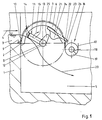
- an overflow edge 2 is formed, over which the large amount of water 3 to be screened flows according to arrow 4.
- the amount of water 3 comes, for example, from a retention basin, a river or the like.
- An overflow basin 5 adjoins the overflow edge 2 or the wall 1, into which only purified water passes, which can be removed from there or passed on.
- the new device is shown relative to the overflow edge 2 with its essential, basic parts.
- the rake bars 6 have extensions 9 facing the overflow edge 2, with which they are placed on the overflow edge 2. The attachment of the device at the place of use is otherwise not shown.
- the rake bars 6, the number and spacing of which can be chosen constructively next to one another, that is to say in the direction of the axis 8, form on their outside a separating surface 10 which begins at the overflow edge 2 and extends in an arc upwards. It can be seen that the separating surface 10 can expand with the amount of water 3 above the overflow edge 2. This ensures that the separating surface 10 adapts itself automatically to the amount of water or is available for different amounts of water.
- the rake bars 6 are fixed in place.
- a transfer unit 11 is assigned to the rake bars 6 and the separating surface 10 formed by them, in detail has a shaft 12 and arms 13 projecting radially thereon. Fingers 14 are attached to the arms 13, their geometry and arrangement being matched to the arrangement of the rake bars 6. The fingers 14 reach through the spaces between the rake bars 6 and extend to a certain extent beyond the outer circumference of the cylinder jacket 7 or the separating surface 10.
- the shaft 12 or the take-over unit 11 is driven continuously or in cycles according to arrow 15 by a drive (not shown), for example an electric motor, the fingers 14 of the take-over unit 11 entering the spaces between the rake bars 6 in the region of the overflow edge 2 and that transport screenings separated on the separation surface 10 with upwards.
- the screenings then come out of the area of the water quantity 3 and fall over the downwardly curved part of the screen rods 6 into a cross conveyor 16, which can have a housing 17 open at the top, a driven shaft 18 and a conveyor spiral 19. It is understood that the shaft 18 is driven in rotation by a drive, not shown, so that the thrown off screenings are conveyed away to the side. With the exception of the separation surface 10, through which water flows, the separated screenings are located above an indicated line of attack 20 and thus outside the water. It can be seen that the absorption capacity of the overflow basin 5 is limited by the height of the overflow edge 2, so that the cleaned water must be removed from this basin or discharged. When storing, the overflow basin 5 is to be made correspondingly large.
- the device can have a transfer device 21.
- the transfer device 21 has, as an essential component, a comb-shaped rake 22, the individual fingers or rods of which likewise reach through the spaces between the rake rods 6.
- the fingers or sticks are around one horizontal axis 23 is pivotally supported to a limited extent and extends from the outside into the interior of the cylinder jacket 7, the rake bars 6 being penetrated.
- the one end position of the transfer device 21 is shown, which is secured for example by a stop, not shown.
- the fingers or rods of the transfer device 21 have a stop 24 on their underside in the interior of the device, the downward-facing surface of which cooperates with a cam 25 which is arranged on the shaft 12 in a rotationally fixed manner.
- a cam 25 which is arranged on the shaft 12 in a rotationally fixed manner.
- the transfer device 21 serves to transport the screenings over the upper edge 26 of the housing 17 of the cross conveyor 16.
- An advantage of the transfer device 21 is therefore that the cross conveyor 16 can be arranged relatively high. If the cross conveyor 16 is arranged relative to the cylinder jacket 7 in the lower part, the transfer device 21 can generally also be omitted. Otherwise, the transfer device 21 has the task of ensuring that no separated screenings get back into the cleaned water of the overflow basin 5.
- Figure 2 shows a further embodiment of the device, which is basically similar to the device of Figure 1, so that reference can be made to the relevant description.
- the rake bars 6 are different from the embodiment according to FIG. 1, but not fixed in the upper area of the cylinder jacket 7, but in the lower area so that the separating surface 10 is formed on the inside of the rake bars 6.
- the takeover unit 11 can be configured identically to the exemplary embodiment in FIG. 1.
- the fingers 14 can be curved in the direction shown. Also one straight, radial extension of the fingers 14 is possible.
- the fingers 14 protrude relatively further beyond the separating surface 10 in the radial direction, so that a corresponding amount of screenings can be transported upwards from the fingers 14 when the fingers 14 come out of the area of the screen bars 6 and the line of attack 20 of water quantity 3 emerge upwards.
- the transfer device 21 is shown in dashed lines in its starting position in solid lines and in its swung-open position.
- the dashed position is achieved by pivoting over the cam 25 and the stop 24 in the direction of arrow 27.
- the transferred screenings then slide according to arrow 28 into the cross conveyor 16. It goes without saying that a conveyor belt could also be provided as the cross conveyor 16.
- the embodiment which is indicated in FIG. 3 represents a structural union of the separating surface, the take-over unit 11 and the transverse conveyor device 16.
- the separating surface 10 is formed as the inner surface of a sieve wall 29, which also extends over part of the circumference of a cylinder jacket 7.
- the sieve wall 29 is open towards the amount of water 3 and adjoins the overflow edge 2 with an extension 9.
- the sieve wall 29 has openings, for example holes or slots, the geometry and arrangement of which is matched to the fineness of the screenings to be separated.
- the separating surface 10 formed in this way is assigned the take-over unit 11 in the form of a conveying helix 30, which is preferably mounted without a shaft in the housing-like sieve wall 29 and is driven accordingly.
- the outer edge of the conveyor helix 30 repeatedly sweeps along the screen wall 29 and in particular along the separating surface 10, so that the screenings are grasped and conveyed sideways in the direction of the axis 8.
- the device can continue in an upward conveying path 31, in the housing 32 of which a shaft 34 with a conveying helix 35 driven by a motor 33 is provided.
- the shaft 34 can be connected to a universal joint 36 and a shaft stub 37, which carries and drives the shaft which is shaftless over a large part of its length.
- a flap 38 can be provided so that the screenings can be removed and conveyed away at this point. As a rule, however, the screenings are conveyed upwards via the conveyor section 31 and dropped into a container 40 via a chute 39.
Landscapes
- Engineering & Computer Science (AREA)
- Chemical & Material Sciences (AREA)
- General Engineering & Computer Science (AREA)
- Chemical Kinetics & Catalysis (AREA)
- Mechanical Engineering (AREA)
- Civil Engineering (AREA)
- Structural Engineering (AREA)
- Environmental & Geological Engineering (AREA)
- Analytical Chemistry (AREA)
- Life Sciences & Earth Sciences (AREA)
- Hydrology & Water Resources (AREA)
- Water Supply & Treatment (AREA)
- Organic Chemistry (AREA)
- Separation Of Solids By Using Liquids Or Pneumatic Power (AREA)
- Filtration Of Liquid (AREA)
- Structure Of Belt Conveyors (AREA)
- Drilling And Exploitation, And Mining Machines And Methods (AREA)
- Cyclones (AREA)
- Sewage (AREA)
Abstract
Description
Die Erfindung bezieht sich auf eine Vorrichtung zum Reinigen großer Wassermengen von Rechengut an Überlaufkanten, mit den im Oberbegriff des Anspruches 1 angegebenen Merkmalen. Für verschiedene Anwendungsfälle ergibt sich die Notwendigkeit, große Wassermengen zu sieben und von schwimmendem Rechengut zu reinigen. Wenn z. B. Kühlwasser in großer Menge aus einem Fluß entnommen werden soll, wird in der Regel eine Überlaufkante geschaffen und das überlaufende Wasser entnommen. Dieses soll je nach Anforderung frei von Rechengut bis hin zu schwimmenden Schwebestoffen sein. Aber auch in der kommunalen Abwassertechnik stellt sich die Aufgabe des Siebens großer Wassermengen insbesondere bei und nach dem Eintritt eines großen Regenereignisses, beispielsweise eines Gewitterregens. Es fällt dann in relativ kurzer Zeit eine erhebliche Wassermenge an, für deren Bewältigung die Kläranlage nicht ausgelegt ist. Es werden hier Regenrückhaltebecken und Regenüberlaufbecken eingesetzt, um die große Wassermenge zwischenzuspeichern und nach dem Ende des Regenereignisses gezielt abzuarbeiten. Aber auch solche Regenrückhaltebecken haben nur eine begrenzte Aufnahmekapazität, die in selteneren Fällen überschritten wird, so daß das dann anfallende überschüssige Wasser ungeklärt z. B. in einen Fluß geleitet wird. Gerade bei solchen Gewitterregen und insbesondere nach Trockenwetterperioden führt die anfallende Wassermenge eine große Schmutzfracht mit sich, die abgeschieden werden soll.The invention relates to a device for cleaning large amounts of water from screenings at overflow edges, with the features specified in the preamble of
Eine Vorrichtung der eingangs beschriebenen Art ist aus der DE-A-40 37 884 bekannt. Die Abscheidefläche ist als Stück eines Zylindermantels ausgebildet und mit parallel zur Überlaufkante liegender Achse angeordnet. Die Abscheidefläche erstreckt sich über etwa 90° des Zylindermantels, und die Achse des Zylindermantels ist etwa um den Radius des Zylindermantels tiefer als die Überlaufkante vorgesehen, so daß das über die Überlaufkante fließende Wasser etwa am höchsten Punkt des Zylindermantels zugeführt wird. Die Abscheidefläche ist damit flächenmäßig begrenzt, und es besteht die Gefahr, daß nach einem Zusetzen der Abscheidefläche das Wasser über die Vorrichtung ungereinigt überströmt und in einen Ablaufkanal gelangt, der quer zur Strömungsrichtung über die Überlaufkante verläuft. Der Abscheidefläche ist eine um die Achse des Zylindermantels angetriebene Übernahmeeinheit zur Abnahme des an der Abscheidefläche abgeschiedenen Rechenguts zugeordnet. Die Übernahmeeinheit wird durch das überströmende Wasser selbst angetrieben, so daß der Antrieb abhängig von dem Wasserstand über der Überlaufkante ist. Bei einem niedrigen Wasserstand besteht die Gefahr, daß die Übernahmeeinheit nicht mehr angetrieben wird. Bei einem hohen Wasserstand besteht die Gefahr, daß sich die flächenmäßig begrenzte Abscheidefläche schnell zusetzt und das weitere Wasser ungereinigt überströmt.A device of the type described above is known from DE-A-40 37 884. The separating surface is designed as a piece of a cylinder jacket and is arranged with an axis lying parallel to the overflow edge. The separating surface extends over approximately 90 ° of the cylinder jacket, and the axis of the cylinder jacket is provided about the radius of the cylinder jacket lower than the overflow edge, so that the water flowing over the overflow edge approximately at the highest point of the cylinder jacket is fed. The separation area is thus limited in terms of area, and there is a risk that after clogging of the separation area, the water will flow over the device unpurified and into an outlet channel which runs across the overflow edge in the direction of flow. A transfer unit, driven around the axis of the cylinder jacket, is assigned to the separation surface for the removal of the screenings deposited on the separation surface. The transfer unit is driven by the overflowing water itself, so that the drive is dependent on the water level above the overflow edge. If the water level is low, there is a risk that the transfer unit will no longer be driven. If the water level is high, there is a risk that the separating area, which is limited in area, will quickly clog and the further water will flow over unpurified.
Der Erfindung liegt die Aufgabe zugrunde, eine Vorrichtung der eingangs beschriebenen Art aufzuzeigen, mit der große Wassermengen verläßlich gereinigt werden können, ohne daß die Gefahr besteht, daß sich die Abscheidefläche zusetzt.The invention has for its object to provide a device of the type described above with which large amounts of water can be reliably cleaned without the risk that the separation surface clogs.
Erfindungsgemäß wird dies dadurch erreicht, daß die Abscheidefläche mit ihrer Achse etwa auf der Höhe der Überlaufkante angeordnet ist und sich bogenförmig nach oben oder unten über etwa 180° des liegenden Zylindermantels erstreckt, so daß eine Zwangsdurchströmung der Abscheidefläche erfolgt, und daß eine Querfördereinrichtung für den seitlichen Abtransport des abgeschiedenen Rechenguts vorgesehen ist.According to the invention this is achieved in that the separating surface is arranged with its axis approximately at the height of the overflow edge and extends in an arc upwards or downwards over approximately 180 ° of the lying cylinder jacket, so that a forced flow through the separating surface takes place, and in that a transverse conveyor device for the lateral removal of the separated screenings is provided.
Damit wird eine Vorrichtung geschaffen, bei der die wirksame Abscheidefläche zunächst einmal vergrößert ist. Die Abscheidefläche in Form eines Stücks eines Zylindermantels ist mit der Achse des Zylindermantels etwa auf gleicher Höhe wie die Überlaufkante angeordnet, so daß die Möglichkeit besteht, die vergrößerte Abscheidefläche auch auszunutzen. Es findet eine Zwangsdurchströmung statt, d. h. die ankommende Flüssigkeit muß durch die Abscheidefläche hindurchgeleitet werden. Wenn die angetriebene Übernahmeeinheit ausfällt, steigt der Wasserspiegel, und es wird ein weiterer Bereich der Abscheidefläche, der nicht zugesetzt ist, zur Verfügung gestellt. Allenfalls steigt hier der Wasserspiegel. Es besteht insoweit die Möglichkeit, einen intermittierenden Antrieb für die Übernahmeeinheit vorzusehen und beispielsweise in Abhängigkeit eines steigenden Wasserspiegels zu steuern. Es ist aber auch möglich, die Übernahmeeinheit kontinuierlich oder durch eine Zeitsteuerung ausgelöst taktweise zu betreiben. Damit wird eine sich kontinuierlich selbst reinigende Vorrichtung geschaffen, die eine große Betriebssicherheit aufweist. Die Vorrichtung ermöglicht das Abscheiden und Herausholen des Rechenguts aus der durchfließenden großen Wassermenge, so daß dieses Rechengut, beispielsweise Laub, Äste, Getränkedosen u. dgl., nicht erneut abgeschieden werden muß.This creates a device in which the effective separation area is initially enlarged. The separation surface in the form of a piece of a cylinder jacket is arranged with the axis of the cylinder jacket at approximately the same height as the overflow edge, so that there is the possibility of also using the enlarged separation area. There is a forced flow, ie the incoming liquid must be passed through the separating surface. If the driven transfer unit fails, the water level rises and a further area of the separation area that is not clogged is made available. At most, the water level rises here. In this respect, there is the possibility of providing an intermittent drive for the takeover unit and controlling it, for example, as a function of a rising water level. However, it is also possible to operate the takeover unit continuously or in cycles, triggered by a time control. This creates a continuously self-cleaning device that has great operational reliability. The device enables the separation and removal of the screenings from the large amount of water flowing through them, so that these screenings, such as leaves, branches, beverage cans and the like. Like., Does not have to be deposited again.
Es ist eine Querfördereinrichtung für den seitlichen Abtransport des abgeschiedenen Rechenguts vorgesehen, so daß die Durchflußrichtung des Wassers nicht verändert werden muß. Die Querfördereinrichtung hat die Aufgabe, daß Rechengut von der Übernahmeeinheit zu übernehmen und seitlich hinwegzufördern. Als Querfördereinrichtung kann eine Schneckenfördereinrichtung mit Gehäuse, Förderwendel und Antrieb vorgesehen sein. Die Achse der Schneckenfördereinrichtung erstreckt sich wiederum parallel zur Achse des Zylinderabschnittes der Abscheideeinrichtung sowie parallel zur Überlaufkante. Über die Querfördereinrichtung wird das Rechengut hinweggefördert und kann z. B. in einen Container abgeworfen werden.A cross conveyor is provided for the lateral removal of the separated screenings, so that the direction of flow of the water does not have to be changed. The cross conveyor device has the task of taking over the screenings from the take-over unit and conveying them sideways. A screw conveyor device with housing, conveyor helix and drive can be provided as the cross conveyor device. The axis of the screw conveyor device in turn extends parallel to the axis of the cylinder section of the separating device and parallel to the overflow edge. The screenings are conveyed away via the cross conveyor and can e.g. B. dropped into a container.
Die Abscheidefläche kann aus mehreren parallel zueinander angeordneten Rechenstäben bestehen. Als zugeordnete Übernahmeeinheit kann eine die Rechenstäbe durchdringende kammartige Harke vorgesehen sein. Die Abscheidefläche ist damit an einem Rechen aus Rechenstäben gebildet, wobei die Rechenstäbe längs Umfangslinien des Zylinders angeordnet sind und sich über einen Teil des Umfangs jeweils erstrecken. Zwischen den benachbarten Rechenstäben besteht jeweils ein Abstand, durch den die kammartig ausgebildete Harke hindurchgreift, so daß das Rechengut von der Abscheidefläche abgenommen und durch die kammartige Harke aus dem Bereich des durchfließenden Wassers heraustransportiert wird. Gleichzeitig wird damit die Abscheidefläche bei jedem Durchgang der kammartigen Harke gereinigt. Der Abstand der Rechenstäbe voneinander ist maßgeblich für den Abscheidegrad. Bei relativ großen Wassermengen wird das Rechengut im Sinn einer Grobreinigung des Wassers abgeschieden.The separating surface can consist of several rake bars arranged parallel to one another. A comb-like rake penetrating the rake bars can be provided as the assigned take-over unit. The separating surface is thus formed on a rake from rake bars, the rake bars being arranged along circumferential lines of the cylinder and extending over part of the Extend circumference in each case. There is a distance between each of the adjacent rake bars through which the rake-shaped rake reaches so that the screenings are removed from the separation surface and transported out of the area of the water flowing through the rake-like rake. At the same time, the separating surface is cleaned with each pass of the comb-like rake. The distance between the rake bars is decisive for the degree of separation. With relatively large amounts of water, the screenings are separated out in the sense of a rough cleaning of the water.
Es ist aber auch möglich, daß die Abscheidefläche aus einer Siebwandung besteht und als Übernahmeeinheit eine Förderwendel vorgesehen ist. Die Förderwendel streicht dann mit dem Umfang an der Siebwandung entlang und nimmt das abgeschiedene Rechengut mit. Die Ausbildung einer Abscheidefläche an einer Siebwandung gestattet es, auch eine feinere Siebung durchzuführen, also vergleichsweise kleineres Rechengut aus dem Wasser zu entfernen. Die Geometrie der Löcher oder Schlitze in der Siebwandung ist dabei maßgebend für das abgeschiedene Rechengut.However, it is also possible for the separating surface to consist of a sieve wall and for a feed spiral to be provided as the take-over unit. The conveyor spiral then sweeps along the circumference along the screen wall and takes the separated screenings with it. The formation of a separating surface on a sieve wall also allows finer sieving to be carried out, that is to say comparatively smaller screenings can be removed from the water. The geometry of the holes or slots in the screen wall is decisive for the separated screenings.
Bei dieser Ausführungsform kann die Förderwendel zusammen mit der Siebwandung zugleich die Querfördereinrichtung bilden.In this embodiment, the conveyor helix together with the sieve wall can simultaneously form the cross conveyor.
Wenn die Abscheidefläche an einem Rechen als Stück eines Zylindermantels realisiert wird, kann die Abscheidefläche außen oder innen an den Rechenstäben vorgesehen sein. Bei einer Abscheidung außen erstrecken sich die Rechenstäbe im Anschluß an die Überlaufkante bogenförmig nach oben sowie dann wieder abwärts. Wenn die Abscheidefläche innen realisiert ist, erstrecken sich die Rechenstäbe von der Abscheidekante bogenförmig nach unten, von wo sie wieder ansteigen, um gleichsam eine Mulde für das abgeschiedene Rechengut zu bilden.If the separating surface on a rake is realized as a piece of a cylinder jacket, the separating surface can be provided on the outside or inside of the rake bars. In the case of deposition on the outside, the rake bars extend in an arc upward and then downward again after the overflow edge. If the separating surface is realized on the inside, the rake bars extend from the separating edge in an arc downwards, from where they rise again, to form a trough for the separated screenings.
Der Abscheidefläche und der Übernahmeeinheit kann eine Übergabeeinrichtung zugeordnet sein, die kammartig ausgebildet ist und die Rechenstäbe durchsetzt. Diese Übergabeeinrichtung hat die Aufgabe, das Rechengut von der Aufnahmeeinheit zu übernehmen und in den nachgeschalteten Querförderer zu leiten. Die Übergabeeinrichtung selbst ist beweglich angeordnet, um zwischengelagertes Rechengut in den Querförderer zu überführen und damit selbst wieder gereinigt zu werden, um bei einem erneuten Durchgang der Übernahmeeinheit wiederum Rechengut ableiten zu können.The separation surface and the take-over unit can be assigned a transfer device which is comb-shaped and the rulers interspersed. This transfer device has the task of taking over the screenings from the receiving unit and guiding them into the downstream cross conveyor. The transfer device itself is arranged so as to be movable in order to transfer the screenings which are temporarily stored into the cross conveyor and thus to be cleaned again in order to be able to derive screenings when the takeover unit passes through again.
Die Übergabeeinrichtung ist zweckmäßig außerhalb des Umfangs der Übernahmeeinheit schwenkbar gelagert und weist einen Anschlag für einen auf der Welle der Übernahmeeinheit angeordneten Nocken auf. Damit wird vorteilhaft erreicht, daß die Übergabeeinrichtung durch den Antrieb der Übernahmeeinheit taktweise bewegt und gereinigt wird.The transfer device is expediently pivoted outside the scope of the transfer unit and has a stop for a cam arranged on the shaft of the transfer unit. This advantageously ensures that the transfer device is cyclically moved and cleaned by the drive of the transfer unit.
Die Übergabeeinrichtung ist oberhalb der Querfördereinrichtung gelagert und reicht mit ihren kammartigen Zinken in den Umfangsweg der Übernahmeeinheit ein.The transfer device is mounted above the cross conveyor and extends with its comb-like tines into the circumferential path of the transfer unit.
Wenn die Übernahmeeinheit als Schneckenfördereinrichtung ausgebildet ist, deren Gehäuse als Siebwandung fungiert, bildet diese Vorrichtung zugleich die Querfördereinrichtung. Die Förderschnecke kann dann in eine aufwärts gerichtete Förderstrecke übergehen, um z. B. den Abwurf des Rechenguts in einen Container zu ermöglichen oder zu erleichtern.If the takeover unit is designed as a screw conveyor device, the housing of which functions as a sieve wall, this device also forms the transverse conveyor device. The screw conveyor can then merge into an upward conveyor line to z. B. enable or facilitate the dropping of the screenings into a container.
Die Erfindung wird anhand bevorzugter Ausführungsbeispiele weiter erläutert und beschrieben. Es zeigen:
Figur 1- einen Vertikalschnitt durch die wesentlichen Teile der Vorrichtung in einer ersten Ausführungsform,
Figur 2- eine ähnliche Darstellung bei einer zweiten Ausführungsform,
Figur 3- einen Vertikalschnitt durch eine Vorrichtung nach einer dritten Ausführungsform und
Figur 4- eine Seitenansicht der Vorrichtung gemäß
Figur 3.
- Figure 1
- a vertical section through the essential parts of the device in a first embodiment,
- Figure 2
- a similar representation in a second embodiment,
- Figure 3
- a vertical section through a device according to a third embodiment and
- Figure 4
- 3 shows a side view of the device according to FIG. 3.
Im Bereich einer senkrechten Wand 1 ist eine Überlaufkante 2 gebildet, über die die große, zu siebende Wassermenge 3 gemäß Pfeil 4 überströmt. Die Wassermenge 3 kommt beispielsweise aus einem Rückhaltebecken, einem Fluß o. dgl. An die Überlaufkante 2 bzw. die Wand 1 schließt ein Überlaufbecken 5 an, in welches nur gereinigtes Wasser übertritt, welches von dort entnommen oder weitergeleitet werden kann.In the area of a
Die neue Vorrichtung ist relativ zur Überlaufkante 2 mit ihren wesentlichen, prinzipiellen Teilen dargestellt. Es sind bogenförmig gekrümmte Rechenstäbe 6 abständig nebeneinander angeordnet, die sich etwa über 180° eines liegendes Zylindermantels 7 erstrecken, dessen Achse 8 parallel und etwa auf der Höhe der Überlaufkante 2 angeordnet ist. Die Rechenstäbe 6 weisen der Überlaufkante 2 zugekehrt Fortsätze 9 auf, mit denen sie auf die Überlaufkante 2 aufgesetzt sind. Die Befestigung der Vorrichtung am Einsatzort ist ansonsten nicht dargestellt.The new device is shown relative to the
Die Rechenstäbe 6, deren Anzahl und Abstand nebeneinander, also in Richtung der Achse 8, konstruktiv gewählt werden kann, bilden auf ihrer Außenseite eine Abscheidefläche 10, die an der Überlaufkante 2 beginnt und sich bogenförmig nach aufwärts erstreckt. Es ist erkennbar, daß die Abscheidefläche 10 mit der Höhe der Wassermenge 3 über der Überlaufkante 2 sich ausdehnen kann. Damit wird erreicht, daß sich die Abscheidefläche 10 gleichsam selbsttätig an die Wassermenge anpaßt bzw. für unterschiedliche Wassermengen zur Verfügung steht. Die Rechenstäbe 6 sind ortsfest gelagert.The rake bars 6, the number and spacing of which can be chosen constructively next to one another, that is to say in the direction of the
Den Rechenstäben 6 und der von diesen gebildeten Abscheidefläche 10 ist eine Übernahmeeinheit 11 zugeordnet, die im Einzelnen eine Welle 12 und daran radial abstehende Arme 13 aufweist. An den Armen 13 sind Finger 14 befestigt, deren Geometrie und Anordnung auf die Anordnung der Rechenstäbe 6 abgestimmt ist. Die Finger 14 greifen durch die Zwischenräume zwischen den Rechenstäben 6 hindurch und erstrecken sich über den äußeren Umfang des Zylindermantels 7 bzw. der Abscheidefläche 10 hinaus um ein gewisses Maß. Die Welle 12 bzw. die Übernahmeeinheit 11 wird durch einen nicht dargestellten Antrieb, beispielsweise einen Elektromotor, gemäß Pfeil 15 kontinuierlich oder taktweise umlaufend angetrieben, wobei die Finger 14 der Übernahmeeinheit 11 im Bereich der Überlaufkante 2 in die Zwischenräume zwischen den Rechenstäben 6 eintreten und das an der Abscheidefläche 10 abgeschiedene Rechengut mit nach aufwärts transportieren. Das Rechengut gelangt dann aus dem Bereich der Wassermenge 3 heraus und fällt über den abwärts gekrümmten Teil der Rechenstäbe 6 in eine Querfördereinrichtung 16, die ein oben offenes Gehäuse 17, eine angetriebene Welle 18 und eine Förderwendel 19 aufweisen kann. Es versteht sich, daß die Welle 18 durch einen nicht dargestellten Antrieb drehend angetrieben wird, so daß das abgeworfene Rechengut seitlich hinweggefördert wird. Mit Ausnahme der Abscheidefläche 10, die vom Wasser durchströmt wird, befindet sich das abgeschiedene Rechengut oberhalb einer angedeuteten Überfallinie 20 und damit außerhalb des Wassers. Es ist ersichtlich, daß die Aufnahmekapazität des Überlaufbeckens 5 durch die Höhe der Überlaufkante 2 begrenzt ist, so daß das gereinigte Wasser aus diesem Becken entnommen oder abgeleitet werden muß. Bei einer Speicherung ist das Überlaufbecken 5 entsprechend groß zu gestalten.A
Um den Transport des Rechenguts von der Übernahmeeinheit 11 in die Querfördereinrichtung 16 zu begünstigen oder zu verbessern, kann die Vorrichtung eine Übergabeeinrichtung 21 aufweisen. Die Übergabeeinrichtung 21 weist als wesentlichen Bestandteil eine kammartig ausgebildete Harke 22 auf, deren einzelne Finger oder Stäbe ebenfalls durch die Zwischenräume zwischen den Rechenstäben 6 hindurchgreifen. Die Finger oder Stäbe sind um eine horizontale Achse 23 begrenzt schwenkbar gelagert und erstrecken sich von außen in das Innere des Zylindermantels 7, wobei die Rechenstäbe 6 durchsetzt werden. In Figur 1 ist die eine Endstellung der Übergabeeinrichtung 21 dargestellt, die beispielsweise durch einen nicht dargestellten Anschlag gesichert ist. Einige oder alle Finger oder Stäbe der Übergabeeinrichtung 21 besitzen auf ihrer Unterseite im Innenraum der Vorrichtung einen Anschlag 24, dessen nach unten gekehrte Oberfläche mit einem Nocken 25 zusammenarbeitet, der drehfest auf der Welle 12 angeordnet ist. Beim Umlauf der Welle 12 und damit des Nockens 25 hebt dieser die Übergabeeinrichtung 21 in eine steilere Stellung nach oben aus, so daß auf der nach außen freien Oberfläche der Harke 22 liegengebliebenes Rechengut an der nun steiler gestellten Übergabeeinrichtung herabrutscht und damit in die Querfördereinrichtung 16 einfällt. Gleichzeitig dient die Übergabeeinrichtung 21 dem Transport des Rechenguts über die obere Kante 26 des Gehäuses 17 der Querfördereinrichtung 16 hinweg. Ein Vorteil der Übergabeeinrichtung 21 besteht somit darin, daß die Querfördereinrichtung 16 relativ hoch angeordnet werden kann. Wenn die Querfördereinrichtung 16 relativ zum Zylindermantel 7 im unteren Teil angeordnet wird, kann die Übergabeeinrichtung 21 in der Regel auch entfallen. Die Übergabeeinrichtung 21 hat ansonsten die Aufgabe, sicherzustellen, daß kein abgeschiedenes Rechengut in das gereinigte Wasser des Überlaufbeckens 5 zurückgelangt.In order to favor or improve the transport of the screenings from the take-over
Figur 2 zeigt eine weitere Ausführungsform der Vorrichtung, die prinzipiell ähnlich wie die Vorrichtung gemäß Figur 1 aufgebaut ist, so daß auf die diesbezügliche Beschreibung verwiesen werden kann. Die Rechenstäbe 6 sind hier abweichend zu der Ausführungsform gemäß Figur 1, jedoch nicht im oberen Bereich des Zylindermantels 7, sondern im unteren Bereich ortsfest angeordnet, so daß die Abscheidefläche 10 innen an den Rechenstäben 6 gebildet ist. Die Übernahmeeinheit 11 kann identisch wie bei dem Ausführungsbeispiel der Figur 1 ausgebildet sein. Die Finger 14 können in der gezeigten Richtung gebogen ausgebildet werden. Auch eine gerade, radiale Erstreckung der Finger 14 ist möglich. Es ist hier erkennbar, daß die Finger 14 relativ weiter über die Abscheidefläche 10 in radialer Richtung überstehen, so daß eine entsprechend Menge Rechengut von den Fingern 14 nach aufwärts transportiert werden kann, wenn die Finger 14 aus dem Bereich der Rechenstäbe 6 und der Überfallinie 20 der Wassermenge 3 nach oben austreten.Figure 2 shows a further embodiment of the device, which is basically similar to the device of Figure 1, so that reference can be made to the relevant description. The rake bars 6 are different from the embodiment according to FIG. 1, but not fixed in the upper area of the
Die Übergabeeinrichtung 21 ist in ihrer Ausgangslage in durchgezogener Linienführung und in ihrer aufgeschwenkten Stellung gestrichelt dargestellt. Die gestrichelte Stellung wird durch Verschwenkung über den Nocken 25 und den Anschlag 24 in Richtung des Pfeils 27 erreicht. Das übergebene Rechengut rutscht dann gemäß Pfeil 28 in die Querfördereinrichtung 16. Es versteht sich, daß als Querfördereinrichtung 16 auch ein Förderband vorgesehen sein könnte.The
Die Ausführungsform, die in Figur 3 angedeutet ist, stellt eine bauliche Vereinigung der Abscheidefläche, der Übernahmeeinheit 11 und der Querfördereinrichtung 16 dar. Die Abscheidefläche 10 ist als Innenfläche einer Siebwandung 29 gebildet, die sich ebenfalls über einen Teil des Umfangs eines Zylindermantels 7 erstreckt. Die Siebwandung 29 ist der Wassermenge 3 zugekehrt offen gestaltet und schließt mit einem Fortsatz 9 an die Überlaufkante 2 an. Die Siebwandung 29 weist Durchbrechungen, beispielsweise Löcher oder Schlitze, auf, deren Geometrie und Anordnung auf die Feinheit des abzuscheidenden Rechenguts abgestimmt ist. Der damit gebildeten Abscheidefläche 10 ist die Übernahmeeinheit 11 in Form einer Förderwendel 30 zugeordnet, die bevorzugt wellenlos in der gehäuseartigen Siebwandung 29 gelagert ist und entsprechend angetrieben wird. Die äußere Kante der Förderwendel 30 streicht dabei immer wieder an der Siebwandung 29 und insbesondere an der Abscheidefläche 10 entlang, so daß das Rechengut erfaßt und seitlich in Richtung der Achse 8 hinweggefördert wird.The embodiment which is indicated in FIG. 3 represents a structural union of the separating surface, the take-over
Aus Figur 4 ist erkennbar, daß sich die Vorrichtung in einer aufwärts gerichtete Förderstrecke 31 fortsetzen kann, in deren Gehäuse 32 eine von einem Motor 33 angetriebene Welle 34 mit Förderwendel 35 vorgesehen ist. Die Welle 34 kann mit einem Kardangelenk 36 und einem Wellenstummel 37 verbunden sein, der die auf einem großen Teil ihrer Länge wellenlose Förderwendel trägt und antreibt. Es kann eine Klappe 38 vorgesehen sein, um an dieser Stelle das Rechengut entnehmen und hinwegfördern zu können. In der Regel jedoch wird das Rechengut über die Förderstrecke 31 nach aufwärts gefördert und über eine Schurre 39 in einen Container 40 abgeworfen.It can be seen from FIG. 4 that the device can continue in an upward conveying
- 1 -1 -
- Wandwall
- 2 -2 -
- ÜberlaufkanteOverflow edge
- 3 -3 -
- WassermengeAmount of water
- 4 -4 -
- Pfeilarrow
- 5 -5 -
- ÜberlaufbeckenOverflow basin
- 6 -6 -
- RechenstabSlide rule
- 7 -7 -
- ZylindermantelCylinder jacket
- 8 -8th -
- Achseaxis
- 9 -9 -
- FortsatzContinuation
- 10 -10 -
- AbscheideflächeSeparation area
- 11 -11 -
- ÜbernahmeeinheitTakeover unit
- 12 -12 -
- Wellewave
- 13 -13 -
- Armpoor
- 14 -14 -
- Fingerfinger
- 15 -15 -
- Pfeilarrow
- 16 -16 -
- QuerfördereinrichtungCross conveyor
- 17 -17 -
- Gehäusecasing
- 18 -18 -
- Wellewave
- 19 -19 -
- FörderwendelFunding spiral
- 20 -20 -
- ÜberfallinieRaid line
- 21 -21 -
- ÜbergabeeinrichtungTransfer device
- 22 -22 -
- Harkerake
- 23 -23 -
- Achseaxis
- 24 -24 -
- Anschlagattack
- 25 -25 -
- Nockencam
- 26 -26 -
- KanteEdge
- 27 -27 -
- Pfeilarrow
- 28 -28 -
- Pfeilarrow
- 29 -29 -
- SiebwandungSieve wall
- 30 -30 -
- FörderwendelFunding spiral
- 31 -31 -
- FörderstreckeConveyor line
- 32 -32 -
- Gehäusecasing
- 33 -33 -
- Motorengine
- 34 -34 -
- Wellewave
- 35 -35 -
- FörderwendelFunding spiral
- 36 -36 -
- Kardangelenkuniversal joint
- 37 -37 -
- WellenstummelWave stub
- 38 -38 -
- Klappeflap
- 39 -39 -
- SchurreChute
- 40 -40 -
- ContainerContainer
Claims (10)
- Device for cleaning large quantities of water (3) from debris at overflow edges (2), especially from rain water reservoirs, rivers, etc., with a stationary separation area (10), which is formed as a section of a cylinder jacket (7) with an axis (8) parallel to the overflow edge, through which the quantity of water flows, where a takeover device (11), which is driven about an axis (8) of the cylinder jacket (7), is assigned to the separation area (10) for removing the debris separated at the separation area (10), wherein the separation area (10) with its axis (8) is arranged at about the height of the overflow edge (2) and extends arching to the top or bottom over about 180° of the lying cylinder jacket (7), so that there is a forced flow through the separation area (10), and that a transverse conveyor (16) for transporting the separated debris to the side is provided.
- A device according to claim 1, wherein the separation area (10) is comprised of a number of grating bars (6) arranged parallel to each other and a comb-like rake (22) penetrating the grating bars (6) is provided as the takeover device (11).
- A device according to claim 1, wherein the separation area (10) is comprised of a screen (29) and that the takeover device (11) is provided as a conveyor helix (30).
- A device according to claim 3, wherein the conveyor helix (30) in conjunction with the screen (29) forms the transverse conveyor (16).
- A device according to claim 4, wherein the transverse conveyor (16) has a screw conveyor device with a housing (17), a conveyor helix (19), and a drive.
- A device according to claim 1 or 2, wherein the separation area (10) is provided on the outside or inside of the grating bars (6).
- A device according to claim 6, wherein a passing-on device (21), which is formed in a comb-like fashion and penetrates the grating bars (6), is assigned to the separation area (10) and the takeover device (11).
- A device according to claim 7, wherein the passing-on device (21) is supported swivelling outside the perimeter of the takeover device (11) and has a stop (24) for a cam (25) arranged on the shaft (12) of the takeover device (11).
- A device according to claims 7 and 8, wherein the passing-on device (21) is supported above the transverse conveyor (16).
- A device according to claim 3, wherein the conveyor helix (30) device merges into an upwards directed conveyor line (31).
Applications Claiming Priority (2)
| Application Number | Priority Date | Filing Date | Title |
|---|---|---|---|
| DE4237123A DE4237123C2 (en) | 1992-11-03 | 1992-11-03 | Device for cleaning large amounts of water from screenings |
| DE4237123 | 1992-11-03 |
Publications (2)
| Publication Number | Publication Date |
|---|---|
| EP0596332A1 EP0596332A1 (en) | 1994-05-11 |
| EP0596332B1 true EP0596332B1 (en) | 1996-05-15 |
Family
ID=6472009
Family Applications (1)
| Application Number | Title | Priority Date | Filing Date |
|---|---|---|---|
| EP93117013A Expired - Lifetime EP0596332B1 (en) | 1992-11-03 | 1993-10-21 | Device for cleaning large quantities of water from debris |
Country Status (10)
| Country | Link |
|---|---|
| US (1) | US5422000A (en) |
| EP (1) | EP0596332B1 (en) |
| JP (1) | JP3479330B2 (en) |
| KR (1) | KR100296938B1 (en) |
| CN (1) | CN1052285C (en) |
| AT (1) | ATE138141T1 (en) |
| CZ (1) | CZ232393A3 (en) |
| DE (2) | DE4237123C2 (en) |
| PL (1) | PL172986B1 (en) |
| RU (1) | RU2117735C1 (en) |
Families Citing this family (17)
| Publication number | Priority date | Publication date | Assignee | Title |
|---|---|---|---|---|
| DE19517101C1 (en) * | 1995-05-10 | 1996-12-05 | Huber Hans Gmbh Maschinen Und | Removal system for floating solids in rainwater overflow |
| KR20010002905A (en) * | 1999-06-18 | 2001-01-15 | 배수현 | The collection device of waterways sewage |
| EP1223252A3 (en) * | 2001-01-11 | 2002-12-18 | Mono Pumps Limited | Screening device |
| GB2370999A (en) * | 2001-01-11 | 2002-07-17 | Mono Pumps Ltd | A screening device with a rotating cleaning member |
| DE10158612A1 (en) * | 2001-11-29 | 2003-06-12 | Kurt Zeuner | Solids retaining device, especially for relief drain constructions, comprises curved segment shaped screen with rotary cleaning device |
| CN1294339C (en) * | 2003-06-12 | 2007-01-10 | 上海隧道工程股份有限公司 | Articulated screw conveying machine |
| US7310130B2 (en) * | 2004-10-05 | 2007-12-18 | Asml Netherlands B.V. | Lithographic apparatus and position measuring method |
| CN102677634B (en) * | 2011-03-17 | 2014-09-03 | 哈尔滨盛迪电力设备有限公司 | Cleaning device for trash rack at water intake in hydropower station reservoir zone |
| US10486091B2 (en) * | 2013-06-03 | 2019-11-26 | Aqseptence Group, Inc. | Continuous belt screen |
| CN103613149B (en) * | 2013-11-26 | 2016-07-06 | 刘晓静 | A kind of water wheels rotary grate |
| CN104030456B (en) * | 2014-05-21 | 2015-12-09 | 湖北大学 | A kind of hydro powered type biological filter dam water cleaning systems |
| CN106567364B (en) * | 2016-10-20 | 2018-08-24 | 湖南省汇杰勘测设计股份有限公司 | It is a kind of can auto purification water quality environmentally friendly dam |
| KR101959509B1 (en) * | 2018-07-26 | 2019-03-18 | (주)랜드로드 | Storm water drainage pollutant filtration devices and monitoring system |
| WO2023287386A1 (en) * | 2021-07-11 | 2023-01-19 | İzmi̇r Yüksek Teknoloji̇ Ensti̇tüsü Rektörlüğü | Autonomous coanda type water intake structure |
| CN113529675B (en) * | 2021-08-04 | 2023-05-12 | 潘守成 | Water surface garbage collection device for hydraulic engineering |
| DE102022111102A1 (en) | 2022-05-05 | 2023-11-09 | Oliver Kraus | Separation system for removing solids from wastewater |
| CN116024943B (en) * | 2023-02-16 | 2024-01-02 | 甘肃省水利水电勘测设计研究院有限责任公司 | Reservoir dam water source scheduling and diverting device with dirt interception function |
Family Cites Families (43)
| Publication number | Priority date | Publication date | Assignee | Title |
|---|---|---|---|---|
| US493403A (en) * | 1893-03-14 | holmes | ||
| DE148021C (en) * | ||||
| DE212048C (en) * | ||||
| US184815A (en) * | 1876-11-28 | Improvement in apparatus for treating substances with hydrocarbon | ||
| US546708A (en) * | 1895-09-24 | Walter s | ||
| GB191306172A (en) * | 1913-03-12 | 1914-02-19 | Frederick William Jones | Improvements in or connected with Screening Apparatus and the like for the Treatment of Sewage and other purposes. |
| US1143496A (en) * | 1914-08-04 | 1915-06-15 | Larkin Briles | Automatic cleaner for fish-screens. |
| CH190659A (en) * | 1936-02-15 | 1937-05-15 | Aine Jonneret Fils | Device for the purification of excess water from pipes. |
| US2776755A (en) * | 1951-02-14 | 1957-01-08 | Wittemann Company Inc | Apparatus for straining liquids |
| US2830695A (en) * | 1955-12-16 | 1958-04-15 | Marion H Fennimore | Flexible screw conveyor |
| US2910181A (en) * | 1956-07-02 | 1959-10-27 | Passavant Werke | Combined rake and crushing system |
| US2929504A (en) * | 1958-05-19 | 1960-03-22 | Chain Belt Co | Waste-flow screening apparatus |
| US3255074A (en) * | 1964-04-03 | 1966-06-07 | Beloit Corp | Headbox for paper-making machine |
| US3559667A (en) * | 1968-12-11 | 1971-02-02 | Gen Motors Corp | Governor |
| DE6812487U (en) * | 1968-12-18 | 1969-06-26 | Atlas Mak Maschb Gmbh Fa | DEVICE FOR INDEPENDENT ACCOUNT FILING |
| DE2142540A1 (en) * | 1971-08-25 | 1973-03-01 | Benno Reiche | RAKE CLEANER |
| DE2460355C3 (en) * | 1974-12-20 | 1978-11-09 | Maschinenfabrik Hellmut Geiger Gmbh & Co Kg, 7500 Karlsruhe | Drive for lifting devices with occasional mechanical overload |
| GB1525871A (en) * | 1977-01-24 | 1978-09-20 | Longwood Eng Co Ltd | Scraper device for the rakes or the like of mechanically cleaned screens and a screen embodying such a scraper |
| US4153557A (en) * | 1978-01-30 | 1979-05-08 | Mitsutaka Hori | Bar screen |
| DE2944047A1 (en) * | 1979-10-31 | 1981-06-11 | Passavant-Werke Michelbacher Hütte, 6209 Aarbergen | ARCH RECTIFIER CLEANING DEVICE |
| US4424129A (en) * | 1982-06-28 | 1984-01-03 | Bunger Richard E | Dewatering apparatus for waste recovery systems |
| US4415462A (en) * | 1982-08-12 | 1983-11-15 | Finch Harvey E | Self-cleaning screen |
| CH660854A5 (en) * | 1983-06-01 | 1987-05-29 | Arag Apparatebau | DEVICE FOR SEPARATING COARSE GOODS FROM A FLOWABLE MEDIUM. |
| DE3322578C2 (en) * | 1983-06-14 | 1986-01-16 | Sulzer-Escher Wyss GmbH, 7980 Ravensburg | Sorting device |
| US4713179A (en) * | 1986-03-14 | 1987-12-15 | Goedderz Sr Stanley J | Removable culvert grate |
| CH667483A5 (en) * | 1986-10-17 | 1988-10-14 | Werner Nill | DEVICE FOR CLEANING A SCREEN OR RAKE IN A WASTEWATER SYSTEM. |
| DE8707094U1 (en) * | 1987-05-16 | 1987-09-03 | Bionik GmbH Innovative Technik für die Umwelt, 6200 Wiesbaden | Device for separating mechanical impurities from flowing liquids |
| DE3716434C1 (en) * | 1987-05-16 | 1988-12-08 | Hans-Georg Huber | Device for removing screenings and / or screenings from liquid flowing in a channel |
| SE458862B (en) * | 1988-03-18 | 1989-05-16 | Ola Mileson | DEVICE FOR SEPARATION AND TRANSPORT OF MATERIALS |
| SU1605964A1 (en) * | 1988-06-13 | 1990-11-15 | Украинский научно-исследовательский институт механизации и электрификации сельского хозяйства | Device for removing large impurities from manure |
| DE3820212A1 (en) * | 1988-06-14 | 1989-12-21 | Heinz Dipl Ing Deiters | Arcuate screen with overhead-loading screen cleaner for clarification plants |
| JP2600302B2 (en) * | 1988-06-29 | 1997-04-16 | 三菱樹脂株式会社 | Rainwater infiltration basin |
| DE3910389C1 (en) * | 1989-03-31 | 1990-08-30 | Hans-Georg Dipl.-Ing. 8434 Berching De Huber | |
| SU1663135A1 (en) * | 1989-06-08 | 1991-07-15 | Ленинградский инженерно-строительный институт | Flood-gate for drainage water |
| US5006236A (en) * | 1989-09-25 | 1991-04-09 | Hallco Fabricators, Inc. | Contaminant entrained flow separating apparatus |
| US5110461A (en) * | 1990-09-05 | 1992-05-05 | Abel Guenther | Apparatus for separating liquids and solids |
| JPH0661412B2 (en) * | 1990-03-12 | 1994-08-17 | 清庵工業株式会社 | Overflow filter |
| DE9113761U1 (en) * | 1990-11-05 | 1992-09-10 | Klasnic, Branko, Dipl.-Ing., 81925 München | Device for the mechanical cleaning of contaminated liquids |
| JPH0684637B2 (en) * | 1990-11-07 | 1994-10-26 | 錦一郎 増尾 | Rainwater drainage channel with a garbage can |
| FI87186C (en) * | 1990-11-19 | 1992-12-10 | Ekotuotanto Ab Oy | Screw Grating |
| DE4037884A1 (en) * | 1990-11-28 | 1992-06-04 | Hartl Thomas Dominik | Rake cleaner in hydroelectric plant - incorporates frame with cleaning hooks rotating on horizontal axis |
| DE9205674U1 (en) * | 1991-04-25 | 1992-07-23 | Klasnic, Branko, 8000 München | Device for the mechanical cleaning of liquids in channels or containers |
| US5232587A (en) * | 1992-03-02 | 1993-08-03 | Tom Hegemier | Stormwater inlet filter |
-
1992
- 1992-11-03 DE DE4237123A patent/DE4237123C2/en not_active Expired - Fee Related
-
1993
- 1993-10-21 AT AT93117013T patent/ATE138141T1/en not_active IP Right Cessation
- 1993-10-21 EP EP93117013A patent/EP0596332B1/en not_active Expired - Lifetime
- 1993-10-21 DE DE59302596T patent/DE59302596D1/en not_active Expired - Fee Related
- 1993-10-28 KR KR1019930022638A patent/KR100296938B1/en not_active IP Right Cessation
- 1993-10-29 US US08/145,394 patent/US5422000A/en not_active Expired - Lifetime
- 1993-10-29 PL PL93300894A patent/PL172986B1/en not_active IP Right Cessation
- 1993-11-02 CZ CZ932323A patent/CZ232393A3/en unknown
- 1993-11-02 JP JP27458493A patent/JP3479330B2/en not_active Expired - Fee Related
- 1993-11-03 CN CN93119699A patent/CN1052285C/en not_active Expired - Fee Related
- 1993-11-04 RU RU93050123A patent/RU2117735C1/en active
Also Published As
| Publication number | Publication date |
|---|---|
| PL172986B1 (en) | 1998-01-30 |
| KR940011365A (en) | 1994-06-21 |
| DE4237123C2 (en) | 1995-02-16 |
| CN1052285C (en) | 2000-05-10 |
| CZ232393A3 (en) | 1994-05-18 |
| US5422000A (en) | 1995-06-06 |
| KR100296938B1 (en) | 2001-10-22 |
| JP3479330B2 (en) | 2003-12-15 |
| PL300894A1 (en) | 1994-05-16 |
| DE4237123A1 (en) | 1994-05-05 |
| JPH06200511A (en) | 1994-07-19 |
| ATE138141T1 (en) | 1996-06-15 |
| CN1087152A (en) | 1994-05-25 |
| EP0596332A1 (en) | 1994-05-11 |
| RU2117735C1 (en) | 1998-08-20 |
| DE59302596D1 (en) | 1996-06-20 |
Similar Documents
| Publication | Publication Date | Title |
|---|---|---|
| EP0596332B1 (en) | Device for cleaning large quantities of water from debris | |
| EP0163158B1 (en) | Device for removing a floating material from a liquid flowing in a sewer | |
| EP0259547B1 (en) | Device for removing debris from a flowing sewage liquid | |
| DE3019127C2 (en) | Device for removing screenings from feed channels, in particular from sewage treatment plants | |
| EP1759753A2 (en) | Filter system | |
| DE19524276C2 (en) | Device for removing material to be separated from liquid flowing in a channel | |
| DE4239083A1 (en) | ||
| DE2640803A1 (en) | LAMELLA SEPARATOR FOR SEDIMENTATION (GRAVITATION SEPARATION) | |
| EP1476275B1 (en) | Device for receiving and separating chips created by machine-tools and coolant (overflow) | |
| DE4328476C2 (en) | Device for discharging solid components from a fluid | |
| DE3920196C2 (en) | ||
| EP0722760A1 (en) | Edge filter for liquids | |
| WO1994004276A1 (en) | Conveyor for aggregates produced during reprocessing of residual concrete | |
| DE2512291C2 (en) | Device for separating oil from an oil-water mixture | |
| DE102009012829A1 (en) | Device for classifying, conveying and dewatering sand | |
| DE4006970A1 (en) | Inclined rotary sieves immersed in waste water flow - discharge separated solids into upwardly directed feed worm | |
| DE4235903A1 (en) | Device for removing material to be separated from a liquid flowing in a channel | |
| DE9303867U1 (en) | Cleaning device for cleaning water flowing in a channel | |
| EP0554740B1 (en) | Pump with filtering device | |
| DE19727354A1 (en) | Waste water screening apparatus to remove coarse solid objects | |
| DE3328700A1 (en) | Device for separating out coarse material from a free-flowing medium | |
| DE3109947C2 (en) | Rotary drum filter | |
| DE9205674U1 (en) | Device for the mechanical cleaning of liquids in channels or containers | |
| DE4308333A1 (en) | Cleaning device for cleaning water flowing in a channel | |
| DE102010062970A1 (en) | Device for separation of screenings from liquid, particularly from residual water, has screen basket and wiper interacting with screen area of screen basket |
Legal Events
| Date | Code | Title | Description |
|---|---|---|---|
| PUAI | Public reference made under article 153(3) epc to a published international application that has entered the european phase |
Free format text: ORIGINAL CODE: 0009012 |
|
| AK | Designated contracting states |
Kind code of ref document: A1 Designated state(s): AT BE DE ES FR GB IT NL PT SE |
|
| 17P | Request for examination filed |
Effective date: 19940402 |
|
| 17Q | First examination report despatched |
Effective date: 19950720 |
|
| GRAH | Despatch of communication of intention to grant a patent |
Free format text: ORIGINAL CODE: EPIDOS IGRA |
|
| ITF | It: translation for a ep patent filed | ||
| GRAA | (expected) grant |
Free format text: ORIGINAL CODE: 0009210 |
|
| AK | Designated contracting states |
Kind code of ref document: B1 Designated state(s): AT BE DE ES FR GB IT NL PT SE |
|
| PG25 | Lapsed in a contracting state [announced via postgrant information from national office to epo] |
Ref country code: NL Free format text: LAPSE BECAUSE OF FAILURE TO SUBMIT A TRANSLATION OF THE DESCRIPTION OR TO PAY THE FEE WITHIN THE PRESCRIBED TIME-LIMIT Effective date: 19960515 Ref country code: ES Free format text: THE PATENT HAS BEEN ANNULLED BY A DECISION OF A NATIONAL AUTHORITY Effective date: 19960515 Ref country code: BE Effective date: 19960515 |
|
| REF | Corresponds to: |
Ref document number: 138141 Country of ref document: AT Date of ref document: 19960615 Kind code of ref document: T |
|
| REF | Corresponds to: |
Ref document number: 59302596 Country of ref document: DE Date of ref document: 19960620 |
|
| ET | Fr: translation filed | ||
| GBT | Gb: translation of ep patent filed (gb section 77(6)(a)/1977) |
Effective date: 19960530 |
|
| PG25 | Lapsed in a contracting state [announced via postgrant information from national office to epo] |
Ref country code: SE Effective date: 19960815 |
|
| PG25 | Lapsed in a contracting state [announced via postgrant information from national office to epo] |
Ref country code: PT Effective date: 19960816 |
|
| NLV1 | Nl: lapsed or annulled due to failure to fulfill the requirements of art. 29p and 29m of the patents act | ||
| PLBQ | Unpublished change to opponent data |
Free format text: ORIGINAL CODE: EPIDOS OPPO |
|
| PLBI | Opposition filed |
Free format text: ORIGINAL CODE: 0009260 |
|
| PLBF | Reply of patent proprietor to notice(s) of opposition |
Free format text: ORIGINAL CODE: EPIDOS OBSO |
|
| 26 | Opposition filed |
Opponent name: HERCULES DESIGN & DEVELOPMENT LTD. Effective date: 19970217 |
|
| PLBF | Reply of patent proprietor to notice(s) of opposition |
Free format text: ORIGINAL CODE: EPIDOS OBSO |
|
| PG25 | Lapsed in a contracting state [announced via postgrant information from national office to epo] |
Ref country code: DE Effective date: 19970701 |
|
| PLBO | Opposition rejected |
Free format text: ORIGINAL CODE: EPIDOS REJO |
|
| PLBN | Opposition rejected |
Free format text: ORIGINAL CODE: 0009273 |
|
| STAA | Information on the status of an ep patent application or granted ep patent |
Free format text: STATUS: OPPOSITION REJECTED |
|
| 27O | Opposition rejected |
Effective date: 19990205 |
|
| REG | Reference to a national code |
Ref country code: GB Ref legal event code: 772N Free format text: COUNTERCLAIM FOR REVOCATION LODGED WITH THE PATENTS COURT ON 8 MARCH 2000 (HC-99-04996) |
|
| REG | Reference to a national code |
Ref country code: GB Ref legal event code: 772M Free format text: COUNTERCLAIM FOR REVOCATION WITHDRAWN BY CONSENT ORDER DATED 3 MAY 2001. |
|
| REG | Reference to a national code |
Ref country code: GB Ref legal event code: IF02 |
|
| PGFP | Annual fee paid to national office [announced via postgrant information from national office to epo] |
Ref country code: FR Payment date: 20051019 Year of fee payment: 13 |
|
| REG | Reference to a national code |
Ref country code: GB Ref legal event code: 732E |
|
| REG | Reference to a national code |
Ref country code: FR Ref legal event code: ST Effective date: 20070629 |
|
| PG25 | Lapsed in a contracting state [announced via postgrant information from national office to epo] |
Ref country code: FR Free format text: LAPSE BECAUSE OF NON-PAYMENT OF DUE FEES Effective date: 20061031 |
|
| PGFP | Annual fee paid to national office [announced via postgrant information from national office to epo] |
Ref country code: AT Payment date: 20081028 Year of fee payment: 16 |
|
| PGFP | Annual fee paid to national office [announced via postgrant information from national office to epo] |
Ref country code: IT Payment date: 20091023 Year of fee payment: 17 |
|
| PG25 | Lapsed in a contracting state [announced via postgrant information from national office to epo] |
Ref country code: AT Free format text: LAPSE BECAUSE OF NON-PAYMENT OF DUE FEES Effective date: 20091021 |
|
| PG25 | Lapsed in a contracting state [announced via postgrant information from national office to epo] |
Ref country code: IT Free format text: LAPSE BECAUSE OF NON-PAYMENT OF DUE FEES Effective date: 20101021 |
|
| PGFP | Annual fee paid to national office [announced via postgrant information from national office to epo] |
Ref country code: GB Payment date: 20120315 Year of fee payment: 19 |
|
| GBPC | Gb: european patent ceased through non-payment of renewal fee |
Effective date: 20121021 |
|
| PG25 | Lapsed in a contracting state [announced via postgrant information from national office to epo] |
Ref country code: GB Free format text: LAPSE BECAUSE OF NON-PAYMENT OF DUE FEES Effective date: 20121021 |