EP0595744B1 - Collapsible and stockable pallet, especially for plate-like products - Google Patents
Collapsible and stockable pallet, especially for plate-like products Download PDFInfo
- Publication number
- EP0595744B1 EP0595744B1 EP19930440088 EP93440088A EP0595744B1 EP 0595744 B1 EP0595744 B1 EP 0595744B1 EP 19930440088 EP19930440088 EP 19930440088 EP 93440088 A EP93440088 A EP 93440088A EP 0595744 B1 EP0595744 B1 EP 0595744B1
- Authority
- EP
- European Patent Office
- Prior art keywords
- products
- pallet
- side walls
- piece
- uprights
- Prior art date
- Legal status (The legal status is an assumption and is not a legal conclusion. Google has not performed a legal analysis and makes no representation as to the accuracy of the status listed.)
- Expired - Lifetime
Links
Images
Classifications
-
- B—PERFORMING OPERATIONS; TRANSPORTING
- B65—CONVEYING; PACKING; STORING; HANDLING THIN OR FILAMENTARY MATERIAL
- B65D—CONTAINERS FOR STORAGE OR TRANSPORT OF ARTICLES OR MATERIALS, e.g. BAGS, BARRELS, BOTTLES, BOXES, CANS, CARTONS, CRATES, DRUMS, JARS, TANKS, HOPPERS, FORWARDING CONTAINERS; ACCESSORIES, CLOSURES, OR FITTINGS THEREFOR; PACKAGING ELEMENTS; PACKAGES
- B65D85/00—Containers, packaging elements or packages, specially adapted for particular articles or materials
- B65D85/30—Containers, packaging elements or packages, specially adapted for particular articles or materials for articles particularly sensitive to damage by shock or pressure
- B65D85/48—Containers, packaging elements or packages, specially adapted for particular articles or materials for articles particularly sensitive to damage by shock or pressure for glass sheets
-
- B—PERFORMING OPERATIONS; TRANSPORTING
- B65—CONVEYING; PACKING; STORING; HANDLING THIN OR FILAMENTARY MATERIAL
- B65D—CONTAINERS FOR STORAGE OR TRANSPORT OF ARTICLES OR MATERIALS, e.g. BAGS, BARRELS, BOTTLES, BOXES, CANS, CARTONS, CRATES, DRUMS, JARS, TANKS, HOPPERS, FORWARDING CONTAINERS; ACCESSORIES, CLOSURES, OR FITTINGS THEREFOR; PACKAGING ELEMENTS; PACKAGES
- B65D19/00—Pallets or like platforms, with or without side walls, for supporting loads to be lifted or lowered
- B65D19/02—Rigid pallets with side walls, e.g. box pallets
- B65D19/06—Rigid pallets with side walls, e.g. box pallets with bodies formed by uniting or interconnecting two or more components
- B65D19/08—Rigid pallets with side walls, e.g. box pallets with bodies formed by uniting or interconnecting two or more components made wholly or mainly of metal
- B65D19/10—Rigid pallets with side walls, e.g. box pallets with bodies formed by uniting or interconnecting two or more components made wholly or mainly of metal of skeleton construction, e.g. made of wire
-
- B—PERFORMING OPERATIONS; TRANSPORTING
- B65—CONVEYING; PACKING; STORING; HANDLING THIN OR FILAMENTARY MATERIAL
- B65D—CONTAINERS FOR STORAGE OR TRANSPORT OF ARTICLES OR MATERIALS, e.g. BAGS, BARRELS, BOTTLES, BOXES, CANS, CARTONS, CRATES, DRUMS, JARS, TANKS, HOPPERS, FORWARDING CONTAINERS; ACCESSORIES, CLOSURES, OR FITTINGS THEREFOR; PACKAGING ELEMENTS; PACKAGES
- B65D2519/00—Pallets or like platforms, with or without side walls, for supporting loads to be lifted or lowered
- B65D2519/00004—Details relating to pallets
- B65D2519/00009—Materials
- B65D2519/00049—Materials for the base surface
- B65D2519/00059—Metal
-
- B—PERFORMING OPERATIONS; TRANSPORTING
- B65—CONVEYING; PACKING; STORING; HANDLING THIN OR FILAMENTARY MATERIAL
- B65D—CONTAINERS FOR STORAGE OR TRANSPORT OF ARTICLES OR MATERIALS, e.g. BAGS, BARRELS, BOTTLES, BOXES, CANS, CARTONS, CRATES, DRUMS, JARS, TANKS, HOPPERS, FORWARDING CONTAINERS; ACCESSORIES, CLOSURES, OR FITTINGS THEREFOR; PACKAGING ELEMENTS; PACKAGES
- B65D2519/00—Pallets or like platforms, with or without side walls, for supporting loads to be lifted or lowered
- B65D2519/00004—Details relating to pallets
- B65D2519/00009—Materials
- B65D2519/00154—Materials for the side walls
- B65D2519/00164—Metal
-
- B—PERFORMING OPERATIONS; TRANSPORTING
- B65—CONVEYING; PACKING; STORING; HANDLING THIN OR FILAMENTARY MATERIAL
- B65D—CONTAINERS FOR STORAGE OR TRANSPORT OF ARTICLES OR MATERIALS, e.g. BAGS, BARRELS, BOTTLES, BOXES, CANS, CARTONS, CRATES, DRUMS, JARS, TANKS, HOPPERS, FORWARDING CONTAINERS; ACCESSORIES, CLOSURES, OR FITTINGS THEREFOR; PACKAGING ELEMENTS; PACKAGES
- B65D2519/00—Pallets or like platforms, with or without side walls, for supporting loads to be lifted or lowered
- B65D2519/00004—Details relating to pallets
- B65D2519/00009—Materials
- B65D2519/00223—Materials for the corner elements or corner frames
- B65D2519/00233—Metal
-
- B—PERFORMING OPERATIONS; TRANSPORTING
- B65—CONVEYING; PACKING; STORING; HANDLING THIN OR FILAMENTARY MATERIAL
- B65D—CONTAINERS FOR STORAGE OR TRANSPORT OF ARTICLES OR MATERIALS, e.g. BAGS, BARRELS, BOTTLES, BOXES, CANS, CARTONS, CRATES, DRUMS, JARS, TANKS, HOPPERS, FORWARDING CONTAINERS; ACCESSORIES, CLOSURES, OR FITTINGS THEREFOR; PACKAGING ELEMENTS; PACKAGES
- B65D2519/00—Pallets or like platforms, with or without side walls, for supporting loads to be lifted or lowered
- B65D2519/00004—Details relating to pallets
- B65D2519/00258—Overall construction
- B65D2519/00283—Overall construction of the load supporting surface
- B65D2519/00298—Overall construction of the load supporting surface skeleton type
-
- B—PERFORMING OPERATIONS; TRANSPORTING
- B65—CONVEYING; PACKING; STORING; HANDLING THIN OR FILAMENTARY MATERIAL
- B65D—CONTAINERS FOR STORAGE OR TRANSPORT OF ARTICLES OR MATERIALS, e.g. BAGS, BARRELS, BOTTLES, BOXES, CANS, CARTONS, CRATES, DRUMS, JARS, TANKS, HOPPERS, FORWARDING CONTAINERS; ACCESSORIES, CLOSURES, OR FITTINGS THEREFOR; PACKAGING ELEMENTS; PACKAGES
- B65D2519/00—Pallets or like platforms, with or without side walls, for supporting loads to be lifted or lowered
- B65D2519/00004—Details relating to pallets
- B65D2519/00258—Overall construction
- B65D2519/00313—Overall construction of the base surface
- B65D2519/00328—Overall construction of the base surface shape of the contact surface of the base
- B65D2519/00338—Overall construction of the base surface shape of the contact surface of the base contact surface having a discrete foot-like shape
-
- B—PERFORMING OPERATIONS; TRANSPORTING
- B65—CONVEYING; PACKING; STORING; HANDLING THIN OR FILAMENTARY MATERIAL
- B65D—CONTAINERS FOR STORAGE OR TRANSPORT OF ARTICLES OR MATERIALS, e.g. BAGS, BARRELS, BOTTLES, BOXES, CANS, CARTONS, CRATES, DRUMS, JARS, TANKS, HOPPERS, FORWARDING CONTAINERS; ACCESSORIES, CLOSURES, OR FITTINGS THEREFOR; PACKAGING ELEMENTS; PACKAGES
- B65D2519/00—Pallets or like platforms, with or without side walls, for supporting loads to be lifted or lowered
- B65D2519/00004—Details relating to pallets
- B65D2519/00258—Overall construction
- B65D2519/00492—Overall construction of the side walls
- B65D2519/00532—Frame structures
-
- B—PERFORMING OPERATIONS; TRANSPORTING
- B65—CONVEYING; PACKING; STORING; HANDLING THIN OR FILAMENTARY MATERIAL
- B65D—CONTAINERS FOR STORAGE OR TRANSPORT OF ARTICLES OR MATERIALS, e.g. BAGS, BARRELS, BOTTLES, BOXES, CANS, CARTONS, CRATES, DRUMS, JARS, TANKS, HOPPERS, FORWARDING CONTAINERS; ACCESSORIES, CLOSURES, OR FITTINGS THEREFOR; PACKAGING ELEMENTS; PACKAGES
- B65D2519/00—Pallets or like platforms, with or without side walls, for supporting loads to be lifted or lowered
- B65D2519/00004—Details relating to pallets
- B65D2519/00547—Connections
- B65D2519/00577—Connections structures connecting side walls, including corner posts, to each other
- B65D2519/00582—Connections structures connecting side walls, including corner posts, to each other structures intended to be disassembled, i.e. collapsible or dismountable
- B65D2519/00606—Connections structures connecting side walls, including corner posts, to each other structures intended to be disassembled, i.e. collapsible or dismountable side walls connected via corner posts
-
- B—PERFORMING OPERATIONS; TRANSPORTING
- B65—CONVEYING; PACKING; STORING; HANDLING THIN OR FILAMENTARY MATERIAL
- B65D—CONTAINERS FOR STORAGE OR TRANSPORT OF ARTICLES OR MATERIALS, e.g. BAGS, BARRELS, BOTTLES, BOXES, CANS, CARTONS, CRATES, DRUMS, JARS, TANKS, HOPPERS, FORWARDING CONTAINERS; ACCESSORIES, CLOSURES, OR FITTINGS THEREFOR; PACKAGING ELEMENTS; PACKAGES
- B65D2519/00—Pallets or like platforms, with or without side walls, for supporting loads to be lifted or lowered
- B65D2519/00004—Details relating to pallets
- B65D2519/00547—Connections
- B65D2519/00671—Connections structures connecting corner posts to the pallet
- B65D2519/00676—Structures intended to be disassembled
-
- B—PERFORMING OPERATIONS; TRANSPORTING
- B65—CONVEYING; PACKING; STORING; HANDLING THIN OR FILAMENTARY MATERIAL
- B65D—CONTAINERS FOR STORAGE OR TRANSPORT OF ARTICLES OR MATERIALS, e.g. BAGS, BARRELS, BOTTLES, BOXES, CANS, CARTONS, CRATES, DRUMS, JARS, TANKS, HOPPERS, FORWARDING CONTAINERS; ACCESSORIES, CLOSURES, OR FITTINGS THEREFOR; PACKAGING ELEMENTS; PACKAGES
- B65D2519/00—Pallets or like platforms, with or without side walls, for supporting loads to be lifted or lowered
- B65D2519/00004—Details relating to pallets
- B65D2519/00736—Details
- B65D2519/00805—Means for facilitating the removal of the load
-
- B—PERFORMING OPERATIONS; TRANSPORTING
- B65—CONVEYING; PACKING; STORING; HANDLING THIN OR FILAMENTARY MATERIAL
- B65D—CONTAINERS FOR STORAGE OR TRANSPORT OF ARTICLES OR MATERIALS, e.g. BAGS, BARRELS, BOTTLES, BOXES, CANS, CARTONS, CRATES, DRUMS, JARS, TANKS, HOPPERS, FORWARDING CONTAINERS; ACCESSORIES, CLOSURES, OR FITTINGS THEREFOR; PACKAGING ELEMENTS; PACKAGES
- B65D2519/00—Pallets or like platforms, with or without side walls, for supporting loads to be lifted or lowered
- B65D2519/00004—Details relating to pallets
- B65D2519/00736—Details
- B65D2519/0081—Elements or devices for locating articles
- B65D2519/0082—Elements or devices for locating articles in the side wall
-
- B—PERFORMING OPERATIONS; TRANSPORTING
- B65—CONVEYING; PACKING; STORING; HANDLING THIN OR FILAMENTARY MATERIAL
- B65D—CONTAINERS FOR STORAGE OR TRANSPORT OF ARTICLES OR MATERIALS, e.g. BAGS, BARRELS, BOTTLES, BOXES, CANS, CARTONS, CRATES, DRUMS, JARS, TANKS, HOPPERS, FORWARDING CONTAINERS; ACCESSORIES, CLOSURES, OR FITTINGS THEREFOR; PACKAGING ELEMENTS; PACKAGES
- B65D2519/00—Pallets or like platforms, with or without side walls, for supporting loads to be lifted or lowered
- B65D2519/00004—Details relating to pallets
- B65D2519/00736—Details
- B65D2519/00935—Details with special means for nesting or stacking
- B65D2519/00955—Details with special means for nesting or stacking stackable
- B65D2519/0096—Details with special means for nesting or stacking stackable when empty
-
- B—PERFORMING OPERATIONS; TRANSPORTING
- B65—CONVEYING; PACKING; STORING; HANDLING THIN OR FILAMENTARY MATERIAL
- B65D—CONTAINERS FOR STORAGE OR TRANSPORT OF ARTICLES OR MATERIALS, e.g. BAGS, BARRELS, BOTTLES, BOXES, CANS, CARTONS, CRATES, DRUMS, JARS, TANKS, HOPPERS, FORWARDING CONTAINERS; ACCESSORIES, CLOSURES, OR FITTINGS THEREFOR; PACKAGING ELEMENTS; PACKAGES
- B65D2519/00—Pallets or like platforms, with or without side walls, for supporting loads to be lifted or lowered
- B65D2519/00004—Details relating to pallets
- B65D2519/00736—Details
- B65D2519/0098—Dismountable elements
- B65D2519/00985—Dismountable elements the pallet being not usable as a pallet after dismounting
Definitions
- the present invention relates to the field of packaging and transport of products on pallets, in particular sheet products, in particular glass, and relates to a removable and stackable pallet intended for this purpose.
- pallets with fixed raised edges or pallets with folding edges are commonly used, against one of the edges of which the sheet products are supported, which are wedged, either with inflatable means, or with specially adapted devices which are clamped on said pallets by means of straps.
- the folding pallets have made it possible to overcome the disadvantages of these pallets with fixed edges by ensuring, for example, a folding of two of their edges around the corresponding uprights of a third edge.
- BE-A-767 414 also discloses a demountable and stackable pallet according to the preamble of claim 1 having a rear part pivotally mounted on a bottom element, this rear part being supported at its upper end in housings provided on the corresponding uprights of the side walls. This rear part is not, however, removable, but simply foldable on the bottom.
- EP-A-0 216 690 also describes a device for handling sheet articles, fitted with built-in feet and the rear product support part, or backsplash, is fixed to the bottom part by pinning, so quick change is impossible.
- the products are locked in position by a system of notched transverse bars supported on the products by means of a strap.
- the locking in position is relatively long and complex to implement.
- this device does not allow interchangeability of the different parts, nor their storage in the bottom of the pallet for transport and storage.
- the present invention aims to overcome these drawbacks.
- a removable and stackable pallet in particular for sheet products, essentially constituted by a bottom with edges slightly raised, by two side walls mounted by fitting in the corresponding edges of the bottom, and by a rear wall for supporting the products, characterized in that the rear wall for supporting the products is constituted by an upper crosspiece connected at its ends to two sleeves intended to penetrate into the upper end shortened by corresponding uprights of the side walls and by a lower cross-member connected to the upper cross-member by means of fixed and lateral movable central supports, this lower cross-member resting at its ends against stops provided on the corresponding tubular uprights of the bottom and in that it is provided with a wedging means in position of the products.
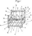
- the pallet in particular for sheet products, is removable and stackable and is essentially constituted by a bottom 1 with edges slightly raised, by two side walls 2 mounted by fitting in the corresponding edges of the bottom 1, by a rear wall 3 of product support and by a means 4 for wedging in position of said products.
- the bottom 1 is further provided with support profiles 10 for the sheet products, these profiles being mounted between the crosspieces 7 with the possibility of transverse displacement by guidance on a median axis 11 connected to the longitudinal members 7 'and passing through corresponding holes in said profiles 10, which bear at their ends on the crosspieces 7.
- the profiles 10 are advantageously cut at said ends.
- Such mounting of the support profiles 10 allows their adjustment in transverse direction and an adaptation to the length of the products to be packaged in the pallet.
- the side walls 2 are preferably in the form of tubular frames which are symmetrical with one another in the mounting position, the uprights 2 'of which fit into the tubular uprights 6 of the bottom 1 and are interconnected by two upper crosspieces 12 and lower 13, the uprights 2 'corresponding to the rear wall of the pallet having a shortened upper part.
- the rear wall 3 for supporting the products consists of an upper cross member 14 connected at its ends to two sleeves 15 intended to penetrate the shortened upper end of the corresponding uprights 2 ′ of the side walls 2 and by a lower cross member 16 connected to the upper cross member 14 by means of fixed central supports 17 and movable lateral supports 18, this lower cross member 16 bearing at its ends against stops 19 provided on the corresponding tubular uprights 6 of the bottom 1.
- the free ends of the uprights 2 ′ of the side walls 2 and of the sleeves 15 have a reinforcement 20 intended to cooperate with the notch of the feet 5 for stacking.
- the movable lateral supports 18 are preferably mounted on the upper 14 and lower 16 crosspieces with the possibility of sliding in grooves 21 cooperating with lugs (not shown) provided on said supports 18.
- lugs not shown
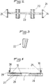
- the means 4 for positioning the products in position is advantageously constituted by at least one wedging wedge 22 mounted on an axis 23 provided at its ends with a device 24 for mounting and adjustable holding on an adjusting means 25 provided on the crosspieces lower 13 of the side walls 2 ( Figures 2 and 3).
- the adjustment means 25 provided on each lower cross member 13 is preferably constituted by a rack and the mounting device 24 and adjustable support is in the form of an arm provided at each end with a stud 26 intended to cooperate with a notch of the rack forming the means 25, this arm being mounted on the corresponding end of the axis 23 with offset , so that the distances from the pins 26 to the axis are different.
- the wedging wedge (s) 22 against the stack of products to be wedged, to determine the pins 26 of the arms of the two ends of the axis 23 which have to be inserted in the notches of the rack forming the adjustment means 25.
- the rear wall 3 for supporting the products can be housed, after disassembly, in the bottom 1 between the sheets 8 connecting the tubular uprights 6, the side walls 2 then being arranged above said wall 3, also between the side walls 8. Furthermore, the means 4 for positioning the products in position is also disposed between said sheets 8, the corners 22 being housed in the intervals determined respectively between the central supports 17 and side 18 of the wall 3, or between the sheets 8 and said lateral supports 18.
- the pallet according to the invention can be completed by a lateral wedging device of known type, namely inflatable or even mechanical constituted by two bars extending along the side walls 2 and guided on the latter with the possibility of pivoting in the direction products to be wedged and locked in position, by means of a slider or the like.
- a lateral wedging device of known type, namely inflatable or even mechanical constituted by two bars extending along the side walls 2 and guided on the latter with the possibility of pivoting in the direction products to be wedged and locked in position, by means of a slider or the like.
- FIG. 4 of the accompanying drawings shows an alternative embodiment of the invention, in which the bottom 1 is provided with support profiles 10 for the sheet products cooperating, by the ends of their core, with notches 27 of a or of several profiles 28 provided on the internal face of the crosspieces 7, the support profiles 10 extending outwardly being each provided with at least two parts 29, projecting outwards and upwards at an acute angle, intended to cooperate with a timing bar 30.
- the support parts 10 it is possible to adjust the support parts 10 as a function of the length of the products to be packaged and to wedge these products laterally with the timing bars 30, which automatically clamp against the edges of said products, thus preventing any ripping.
- the pallet can be completed by a closing wall hooking on the uprights 2 ′ opposite to the rear wall 3 by means of hooking lugs penetrating into said uprights 2 ', this wall being provided, in addition, at its lower part, retaining tabs pressing against the internal face of the corresponding uprights 6 of the bottom 1.
- this front wall can also be stored in the bottom 1, between the sheets 8 and in the overall height delimited by the uprights 6.
- the support profiles 10 provided in the bottom 1, as well as the support profiles 17 and 18 provided on the rear wall 3 and the setting bars 30 are advantageously provided with a coating anti-shock in felt, rubber or the like, intended to prevent any deterioration of the products on their edges or on their edges.
- the invention it is possible to produce a pallet for the packaging of sheet products, in particular fragile products, such as glass and making it possible to ensure a perfect setting and tightening of said products.
- a wedging with the use of racks it is possible to efficiently and securely clamp a pile of products which has started, so that the risks existing to date of overturning of the pile and destruction of the products can be eliminated.
- such a pallet does not require any non-reusable or disposable ancillary element, so that it perfectly meets the criteria of environmental protection and economy.
Description
La présente invention concerne le domaine du conditionnement et du transport de produits sur palettes, en particulier de produits en feuilles, notamment de verre, et a pour objet une palette démontable et gerbable destinée à cet effet.The present invention relates to the field of packaging and transport of products on pallets, in particular sheet products, in particular glass, and relates to a removable and stackable pallet intended for this purpose.
Le transport des matériaux en feuilles, notamment du verre, nécessite généralement l'utilisation de palettes spécialement adaptées, afin de permettre un conditionnement des feuilles posées sur tranche.The transport of sheet materials, in particular glass, generally requires the use of specially adapted pallets, in order to allow packaging of the sheets placed on edge.
A cet effet, on utilise couramment, soit des palettes à bords relevés fixes, soit des palettes à bords repliables, contre l'un des bords desquels s'appuient les produits en feuilles, qui sont calés, soit avec des moyens gonflables, soit avec des dispositifs spécialement adaptés et qui sont serrés sur lesdites palettes au moyen de sangles.To this end, pallets with fixed raised edges or pallets with folding edges are commonly used, against one of the edges of which the sheet products are supported, which are wedged, either with inflatable means, or with specially adapted devices which are clamped on said pallets by means of straps.
Ces palettes connues permettent de satisfaire aux exigences de rangement des produits, mais assurent mal leur maintien et leur calage. En outre, les transformateurs ne vident pas forcément une palette complète en une seule opération, de sorte que les éléments de calage deviennent inopérants et qu'un maintien correct contre un renversement des produits dans la palette n'est plus assuré.These known pallets make it possible to satisfy the storage requirements of the products, but poorly ensure their maintenance and their setting. In addition, the transformers do not necessarily empty a complete pallet in a single operation, so that the wedging elements become inoperative and that correct maintenance against spillage of products in the pallet is no longer guaranteed.
Par ailleurs, dans le cas de palettes à bords relevés fixes, leur encombrement important est très préjudiciable à vide pour le stockage intermédiaire et le transport.Furthermore, in the case of pallets with fixed raised edges, their large size is very prejudicial when empty for intermediate storage and transport.
Les palettes repliables ont permis d'obvier aux inconvénients de ces palettes à bords fixes en assurant, par exemple, un rabattement de deux de leurs bords autour des montants correspondants d'un troisième bord.The folding pallets have made it possible to overcome the disadvantages of these pallets with fixed edges by ensuring, for example, a folding of two of their edges around the corresponding uprights of a third edge.
Cependant, ces palettes repliables connues, qui permettent, certes, une réduction importante de l'encombrement pour le stockage et le gerbage à vide, sont d'une constitution complexe, notamment au niveau des articulations, d'une part, entre les bords latéraux et le troisième bord et, d'autre part, entre le troisième bord et le fond de la palette. Il en résulte une construction lourde et un dépliage et un repliage relativement difficiles pouvant entraîner des risques de blessure pour l'opérateur.However, these known folding pallets, which certainly allow a significant reduction in the size for storage and stacking empty, are of a complex constitution, in particular at the joints, on the one hand, between the lateral edges and the third edge and, on the other hand, between the third edge and the bottom of the pallet. This results in a heavy construction and relatively difficult unfolding and folding which can cause injury risks for the operator.
On connaît également, par BE-A-767 414, une palette démontable et gerbable selon le préambule de la revendication 1 présentant une partie arrière montée de manière pivotante sur un élément de fond, cette partie arrière s'appuyant à son extrémité supérieure dans des logements prévus sur les montants correspondants des parois latérales. Cette partie arrière n'est, cependant, pas démontable, mais simplement repliable sur le fond.BE-A-767 414 also discloses a demountable and stackable pallet according to the preamble of claim 1 having a rear part pivotally mounted on a bottom element, this rear part being supported at its upper end in housings provided on the corresponding uprights of the side walls. This rear part is not, however, removable, but simply foldable on the bottom.
En outre, sur la palette selon ce document il n'est prévu aucune possibilité de rangement des parois latérales après démontage, ni de moyen de calage de produits en feuilles sur une palette incomplètement remplie. De même, il n'existe pas de moyen inférieur de protection empêchant, en cas de fausse manoeuvre, que la fourche d'un gerbeur ou analogue touche le produit en feuilles stocké.In addition, on the pallet according to this document there is no possibility of storing the side walls after dismantling, nor of means for wedging sheet products on a pallet that is not fully filled. Likewise, there is no lower means of protection preventing, in the event of a false maneuver, that the fork of a stacker or the like touches the stored sheet product.
Par ailleurs, EP-A-0 216 690 décrit également un dispositif de manutention d'articles en feuilles, muni de pieds encastrables et dont la partie arrière d'appui des produits, ou dosseret, est fixée sur la partie de fond par goupillage, de sorte qu'un changement rapide est impossible.Furthermore, EP-A-0 216 690 also describes a device for handling sheet articles, fitted with built-in feet and the rear product support part, or backsplash, is fixed to the bottom part by pinning, so quick change is impossible.
De plus, le blocage en position des produits est assuré par un système de barres transversales crantées appuyées sur les produits au moyen d'une sangle. Il en résulte que le blocage en position est de mise en oeuvre relativement longue et complexe.In addition, the products are locked in position by a system of notched transverse bars supported on the products by means of a strap. As a result, the locking in position is relatively long and complex to implement.
Enfin, ce dispositif ne permet pas une interchangeabilité des différentes pièces, ni leur rangement dans le fond de la palette pour le transport et le stockage.Finally, this device does not allow interchangeability of the different parts, nor their storage in the bottom of the pallet for transport and storage.
La présente invention a pour but de pallier ces inconvénients.The present invention aims to overcome these drawbacks.
Elle a, en effet, pour objet une palette démontable et gerbable, en particulier pour produits en feuilles, essentiellement constituée par un fond à bords légèrement surélevés, par deux parois latérales montées par emmanchement dans les bords correspondants du fond, et par une paroi arrière d'appui des produits, caractérisée en ce que la paroi arrière d'appui des produits est constituée par une traverse supérieure reliée à ses extrémités à deux manchons destinés à pénétrer dans l'extrémité supérieure raccourcie de montants correspondants des parois latérales et par une traverse inférieure reliée à la traverse supérieure par l'intermédiaire d'appuis centraux fixes et latéraux mobiles, cette traverse inférieure s'appuyant à ses extrémités contre des arrêts prévus sur les montants tubulaires correspondants du fond et en ce qu'elle est munie d'un moyen de calage en position des produits.It has, in fact, for a removable and stackable pallet, in particular for sheet products, essentially constituted by a bottom with edges slightly raised, by two side walls mounted by fitting in the corresponding edges of the bottom, and by a rear wall for supporting the products, characterized in that the rear wall for supporting the products is constituted by an upper crosspiece connected at its ends to two sleeves intended to penetrate into the upper end shortened by corresponding uprights of the side walls and by a lower cross-member connected to the upper cross-member by means of fixed and lateral movable central supports, this lower cross-member resting at its ends against stops provided on the corresponding tubular uprights of the bottom and in that it is provided with a wedging means in position of the products.
L'invention sera mieux comprise, grâce à la description ci-après, qui se rapporte à un mode de réalisation préféré, donné à titre d'exemple non limitatif, et expliqué avec référence aux dessins schématiques annexés, dans lesquels :
- la figure 1 est une vue en perspective de la palette conforme à l'invention ;
- la figure 2 est une vue en plan du moyen de calage ;
- la figure 3 est une vue en élévation latérale d'un coin de calage, et
- la figure 4 est une vue partielle en coupe d'une variante de réalisation du fond de la palette.
- Figure 1 is a perspective view of the pallet according to the invention;
- Figure 2 is a plan view of the timing means;
- FIG. 3 is a side elevation view of a wedging wedge, and
- Figure 4 is a partial sectional view of an alternative embodiment of the bottom of the pallet.
Conformément à l'invention, et comme le montre plus particulièrement, à titre d'exemple, la figure 1 des dessins annexés, la palette, en particulier pour produits en feuilles, est démontable et gerbable et est essentiellement constituée par un fond 1 à bords légèrement surélevés, par deux parois latérales 2 montées par emmanchement dans les bords correspondants du fond 1, par une paroi arrière 3 d'appui des produits et par un moyen 4 de calage en position desdits produits.In accordance with the invention, and as shown more particularly, by way of example, FIG. 1 of the appended drawings, the pallet, in particular for sheet products, is removable and stackable and is essentially constituted by a bottom 1 with edges slightly raised, by two
Le fond 1, qui est pourvu de manière connue de pieds 5 échancrés pour permettre le gerbage, présente à ses coins des éléments de montants tubulaires 6 reliés entre eux, d'une part, au niveau des pieds 5 par des traverses 7 et des longerons 7' en éléments profilés et, d'autre part, au niveau des parois latérales par une tôle 8 s'étendant au-dessus des longerons 7' correspondants, les longerons 7' et traverses 7 étant, en outre, reliés à leur partie inférieure par une tôle de fond 9.The bottom 1, which is provided in a known manner with
Selon une caractéristique de l'invention, le fond 1 est pourvu, en outre, de profilés d'appui 10 pour les produits en feuilles, ces profilés étant montés entre les traverses 7 avec possibilité de déplacement transversal par guidage sur un axe médian 11 relié aux longerons 7' et traversant des perçages correspondants desdits profilés 10, qui s'appuient à leurs extrémités sur les traverses 7. A cet effet, les profilés 10 sont avantageusement découpés auxdites extrémités.According to a characteristic of the invention, the bottom 1 is further provided with
Un tel montage des profilés d'appui 10 permet leur réglage en sens transversal et une adaptation à la longueur des produits à conditionner dans la palette.Such mounting of the
Les parois latérales 2 se présentent, de préférence, sous forme de cadres tubulaires symétriques entre eux en position de montage, dont les montants 2' s'emmanchent dans les montants tubulaires 6 du fond 1 et sont reliés entre eux par deux traverses supérieure 12 et inférieure 13, les montants 2' correspondant à la paroi arrière de la palette présentant une partie supérieure raccourcie.The
La paroi arrière 3 d'appui des produits est constituée par une traverse supérieure 14 reliée à ses extrémités à deux manchons 15 destinés à pénétrer dans l'extrémité supérieure raccourcie des montants 2' correspondants des parois latérales 2 et par une traverse inférieure 16 reliée à la traverse supérieure 14 par l'intermédiaire d'appuis centraux fixes 17 et latéraux mobiles 18, cette traverse inférieure 16 s'appuyant à ses extrémités contre des arrêts 19 prévus sur les montants tubulaires 6 correspondants du fond 1.The
Les extrémités libres des montants 2' des parois latérales 2 et des manchons 15 présentent un renforcement 20 destiné à coopérer avec l'échancrure des pieds 5 pour le gerbage.The free ends of the
Les appuis latéraux mobiles 18 sont montés, de préférence, sur les traverses supérieure 14 et inférieure 16 avec possibilité de coulissement dans des rainures 21 coopérant avec des ergots (non représentés) prévus sur lesdits appuis 18. Ainsi, il est possible de régler l'appui frontal des produits en feuilles, de manière optimale, les appuis latéraux 18 étant déplaçables sur les traverses 14 et 16 en fonction de la longueur desdits produits.The movable
Le moyen 4 de calage en position des produits est avantageusement constitué par au moins un coin de calage 22 monté sur un axe 23 pourvu à ses extrémités d'un dispositif 24 de montage et de maintien réglable sur un moyen de réglage 25 prévu sur les traverses inférieures 13 des parois latérales 2 (figures 2 et 3).The
A cet effet, le moyen de réglage 25 prévu sur chaque traverse inférieure 13 est constitué, de préférence, par une crémaillère et le dispositif 24 de montage et de maintien réglable se présente sous forme d'un bras pourvu à chaque extrémité d'un téton 26 destiné à coopérer avec une encoche de la crémaillère formant le moyen 25, ce bras étant monté sur l'extrémité correspondante de l'axe 23 avec décalage, de telle sorte que les distances des tétons 26 à l'axe soient différentes. Ainsi, il est possible, avant appui définitif du ou des coins de calage 22 contre la pile de produits à caler, de déterminer les tétons 26 des bras des deux extrémités de l'axe 23 devant être insérés dans les encoches de la crémaillère formant le moyen de réglage 25. En effet, par rotation de l'axe 23, il est possible de rapprocher ou d'écarter le ou les coins de calage des produits à caler, de telle sorte que les bras du dispositif 24 s'étendent pratiquement à l'horizontale lors de l'appui du ou des coins 22 contre la pile de produits. Il en résulte que le ou les coins 22 ont tendance à se rapprocher davantage des produits à caler à chaque vibration ou secousse, de sorte que ledit calage est assuré de manière parfaite.To this end, the adjustment means 25 provided on each
Pour la libération des produits, c'est-à-dire pour débloquer le ou les coins 22, il suffit de tirer sur l'axe 23, ce qui a pour effet de faire pivoter ce dernier autour des tétons 26 coopérant avec les encoches de la crémaillère formant le moyen de réglage 25, entraînant un décollement desdits coins 22 de la pile de produits.For the release of the products, that is to say to unlock the corner or
La paroi arrière 3 d'appui des produits peut être logée, après démontage, dans le fond 1 entre les tôles 8 reliant les montants tubulaires 6, les parois latérales 2 étant disposées ensuite au-dessus de ladite paroi 3, également entre les parois latérales 8. Par ailleurs, le moyen 4 de calage en position des produits est également disposé entre lesdites tôles 8, les coins 22 se logeant dans les intervalles déterminés respectivement entre les appuis centraux 17 et latéraux 18 de la paroi 3, ou entre les tôles 8 et lesdits appuis latéraux 18.The
La palette conforme à l'invention peut être complétée par un dispositif de calage latéral de type connu, à savoir gonflable ou encore mécanique constitué par deux barres s'étendant le long des parois latérales 2 et guidés sur ces dernières avec possibilité de pivotement en direction des produits à caler et verrouillage en position, par l'intermédiaire d'un curseur ou autre. Un tel dispositif n'est pas décrit plus en détails, étant déjà connu de l'art antérieur.The pallet according to the invention can be completed by a lateral wedging device of known type, namely inflatable or even mechanical constituted by two bars extending along the
La figure 4 des dessins annexés représente une variante de réalisation de l'invention, dans laquelle le fond 1 est pourvu de profilés 10 d'appui pour les produits en feuilles coopérant, par les extrémités de leur âme, avec des encoches 27 d'un ou de plusieurs profilés 28 prévus sur la face interne des traverses 7, les profilés d'appui 10 s'étendant extérieurement étant pourvus chacun d'au moins deux parties 29,en saillie vers l'extérieur et vers le haut suivant un angle aigu, destinées à coopérer avec une barre de calage 30. Ainsi, il est possible de régler les parties d'appui 10 en fonction de la longueur des produits à conditionner et de caler latéralement cesdits produits avec les barres de calage 30, qui se serrent automatiquement contre les bords desdits produits, empêchant ainsi tout rippage.Figure 4 of the accompanying drawings shows an alternative embodiment of the invention, in which the bottom 1 is provided with
Selon une autre caractéristique de l'invention, non représentée aux dessins annexés, la palette peut être complétée par une paroi de fermeture s'accrochant sur les montants 2' opposés à la paroi arrière 3 par l'intermédiaire de pattes d'accrochage pénétrant dans lesdits montants 2', cette paroi étant munie, en outre, à sa partie inférieure, de pattes de retenue s'appuyant contre la face interne des montants 6 correspondants du fond 1. Ainsi, il est possible de fermer entièrement la palette. Bien entendu, cette paroi avant peut également être rangée dans le fond 1, entre les tôles 8 et dans l'encombrement en hauteur délimité par les montants 6.According to another characteristic of the invention, not shown in the appended drawings, the pallet can be completed by a closing wall hooking on the
Selon une autre caractéristique de l'invention, les profilés d'appui 10 prévus dans le fond 1, ainsi que les profilés d'appui 17 et 18 prévus sur la paroi arrière 3 et les barres de calage 30 sont avantageusement pourvus d'un revêtement anti-choc en feutre, en caoutchouc ou analogues, destiné à éviter toute détérioration des produits sur leurs chants ou sur leurs bords.According to another characteristic of the invention, the
Grâce à l'invention, il est possible de réaliser une palette pour le conditionnement de produits en feuilles, en particulier de produits fragiles, tels que le verre et permettant d'assurer un calage et un serrage parfait desdits produits. En outre, du fait de la prévision d'un calage avec utilisation de crémaillères, il est possible de serrer efficacement et sûrement une pile de produits entamée, de sorte que les risques existant à ce jour de renversement de la pile et de destruction des produits peuvent être éliminés.Thanks to the invention, it is possible to produce a pallet for the packaging of sheet products, in particular fragile products, such as glass and making it possible to ensure a perfect setting and tightening of said products. In addition, due to the provision of a wedging with the use of racks, it is possible to efficiently and securely clamp a pile of products which has started, so that the risks existing to date of overturning of the pile and destruction of the products can be eliminated.
Enfin, du fait de la constitution entièrement démontable de la palette, il est possible de stocker cette dernière en position de non utilisation, par exemple pour un transport de retour de l'utilisateur vers le fournisseur ou pour le stockage intermédiaire, dans un espace extrêmement réduit, ce qui entraîne une réduction correspondante importante des frais de stockage et de transport.Finally, due to the completely removable construction of the pallet, it is possible to store the latter in the non-use position, for example for return transport from the user to the supplier or for intermediate storage, in an extremely space reduced, resulting in a significant corresponding reduction in storage and transport costs.
En outre, une telle palette ne nécessite aucun élément annexe non réutilisable ou jetable, de sorte qu'elle répond parfaitement aux critères de protection de l'environnement et d'économie.In addition, such a pallet does not require any non-reusable or disposable ancillary element, so that it perfectly meets the criteria of environmental protection and economy.
Bien entendu, l'invention n'est pas limitée au mode de réalisation décrit et représenté aux dessins annexés. Des modifications restent possibles, notamment du point de vue de la constitution des divers éléments ou par substitution d'équivalents techniques, sans sortir pour autant du domaine de protection de l'invention, tel que défini dans les revendications.Of course, the invention is not limited to the embodiment described and shown in the accompanying drawings. Modifications remain possible, in particular from the point of view of the constitution of the various elements or by substitution of technical equivalents, without thereby departing from the scope of protection of the invention, as defined in the claims.
Claims (6)
- Collapsible and stackable pallet, in particular for products in sheet form, consisting of a base (1) with slightly raised edges, two side walls (2) mounted by fitting into the corresponding edges of the base (1), and a rear wall (3) for supporting the products, characterised in that the rear wall (3) for supporting the products consists of an upper cross-piece (14) connected at its ends to two sleeves (15) designed to enter the shortened top end of corresponding uprights (2') of the side walls (2) and a lower cross-piece (16) connected to the upper cross-piece (14) by means of fixed central supports (17) and movable side supports (18), this lower cross-piece (16) bearing at its ends against stops (19) provided on the corresponding tubular uprights (6) of the base (1) and in that it is provided with a means (4) for chocking the products in position.
- Pallet according to Claim 1, characterised in that the free ends of the uprights (2') of the side walls (2) and of the sleeves (15) have a reinforcement (20) designed to cooperate with a cutout in the feet (5) for packing.
- Pallet according to Claim 1, characterised in that the movable side supports (18) are preferably mounted on the upper cross-pieces (14) and lower cross-pieces (16) with the possibility of sliding in grooves (21) cooperating with lugs provided on the said supports (18).
- Pallet according to Claim 1, characterised in that the means (4) of checking the products in position consists of at least one chocking wedge (22) mounted on a shaft (23) provided at its ends with a mounting and holding device (24) adjustable on an adjustment means (25) provided on the lower cross-pieces (13) of the side walls (2).
- Pallet according to claim 4, characterised in that the adjustment means (25) provided on each lower cross-piece (13) preferably consists of a rack and the adjustable mounting and holding device (24) is in the form of an arm provided at each end with a stud (26) designed to cooperate with a notch in the rack forming the means (25), this arm being mounted on the corresponding end of the shaft (23) with offset, so that the distances from the studs (26) to the shaft are different.
- Pallet according to claim 1, characterised in that the base (1) is provided with supporting profiled members (10) for the products in sheet form cooperating, through the ends of their web, with notches (27) on one or more profiled members (28) provided on the internal face of the cross-pieces (7), the supporting profiled members (10) extending externally each being provided with at least two parts (29), projecting outwards and upwards at an acute angle, designed to cooperate with a chocking bar (30).
Applications Claiming Priority (2)
| Application Number | Priority Date | Filing Date | Title |
|---|---|---|---|
| FR9213074A FR2697230B1 (en) | 1992-10-26 | 1992-10-26 | Removable and stackable pallet, especially for sheet products. |
| FR9213074 | 1992-10-26 |
Publications (2)
| Publication Number | Publication Date |
|---|---|
| EP0595744A1 EP0595744A1 (en) | 1994-05-04 |
| EP0595744B1 true EP0595744B1 (en) | 1996-12-18 |
Family
ID=9435066
Family Applications (1)
| Application Number | Title | Priority Date | Filing Date |
|---|---|---|---|
| EP19930440088 Expired - Lifetime EP0595744B1 (en) | 1992-10-26 | 1993-10-19 | Collapsible and stockable pallet, especially for plate-like products |
Country Status (4)
| Country | Link |
|---|---|
| EP (1) | EP0595744B1 (en) |
| DE (1) | DE69306735T2 (en) |
| ES (1) | ES2098013T3 (en) |
| FR (1) | FR2697230B1 (en) |
Families Citing this family (4)
| Publication number | Priority date | Publication date | Assignee | Title |
|---|---|---|---|---|
| AUPP245198A0 (en) * | 1998-03-19 | 1998-04-09 | Pagliaro, Luciano M. | A container for transporting articles |
| GB2480673B (en) * | 2010-05-28 | 2014-10-29 | Belron Hungary Kft Zug Branch | Pallet container |
| DE102020001351A1 (en) * | 2020-03-03 | 2021-09-09 | Wilhelm Layher Verwaltungs-Gmbh | Pallet device for the storage and transport of system scaffolding components |
| CN112938165B (en) * | 2020-12-31 | 2023-09-05 | 上海茂趣智能科技有限公司 | Intelligent equipment for automatically storing and taking out goods |
Family Cites Families (3)
| Publication number | Priority date | Publication date | Assignee | Title |
|---|---|---|---|---|
| GB1290052A (en) * | 1970-05-20 | 1972-09-20 | ||
| FR2587305B3 (en) * | 1985-09-16 | 1987-12-04 | Saint Gobain Vitrage | DEVICE FOR HANDLING AND TRANSPORTING SHEET ITEMS, PARTICULARLY GLAZING. |
| DE3843187C1 (en) * | 1988-12-22 | 1990-06-13 | Vegla Vereinigte Glaswerke Gmbh, 5100 Aachen, De |
-
1992
- 1992-10-26 FR FR9213074A patent/FR2697230B1/en not_active Expired - Lifetime
-
1993
- 1993-10-19 EP EP19930440088 patent/EP0595744B1/en not_active Expired - Lifetime
- 1993-10-19 ES ES93440088T patent/ES2098013T3/en not_active Expired - Lifetime
- 1993-10-19 DE DE1993606735 patent/DE69306735T2/en not_active Expired - Fee Related
Also Published As
| Publication number | Publication date |
|---|---|
| DE69306735T2 (en) | 1997-09-11 |
| FR2697230B1 (en) | 1995-01-20 |
| FR2697230A1 (en) | 1994-04-29 |
| DE69306735D1 (en) | 1997-01-30 |
| EP0595744A1 (en) | 1994-05-04 |
| ES2098013T3 (en) | 1997-04-16 |
Similar Documents
| Publication | Publication Date | Title |
|---|---|---|
| WO2012004403A1 (en) | Container, the space of which is adjustable | |
| EP0595744B1 (en) | Collapsible and stockable pallet, especially for plate-like products | |
| EP0648684B1 (en) | Device for positioning coils and packaging method using this device | |
| FR2654703A1 (en) | Folding pallet box | |
| FR2763923A1 (en) | Fluid material storage device | |
| FR3029880A1 (en) | TRANSPORT ASSEMBLY FOR DETACHABLE BRUSHES | |
| EP0216690B1 (en) | Handling device for sheet-shaped articles | |
| EP2253562A1 (en) | Device for transporting prefabricated flat objects. | |
| EP2065310A1 (en) | Container for detached automobile parts | |
| FR2903669A3 (en) | Dismountable container for transporting merchandise, has panels connected with each other by flexible hinges, and assembling units integrated to pallet and belt line so that line determines maximal inner volume with respect to pallet size | |
| EP0883515B1 (en) | Device for releasably fastening cylindrical objects on a vehicle | |
| WO2011086309A1 (en) | Adjustable transporting platform | |
| FR2713132A1 (en) | Device for supporting sections of wood in piles | |
| FR3133179A1 (en) | Foldable pallet box | |
| BE1001359A6 (en) | Piled up containers holding products for sale - having open tops and are held together by rods guided by holes in top flaps and bases | |
| EP0896935A1 (en) | Device for storing drums | |
| FR2892391A1 (en) | Load e.g. log, handling and transporting device, has gussets connected to side rails and cross pieces and formed of section to receive uprights, where each upright is equipped of stop to limit deflection of uprights in gussets | |
| FR2601335A1 (en) | Collapsible pallet box | |
| EP1671890B1 (en) | Container for storing article, having interconnecting corners provided with vertical pillars | |
| FR3085669A1 (en) | ARTICULATED BACKREST HANDLING PALLET | |
| EP0846625A2 (en) | Light and collapsible transport container | |
| FR3085361A1 (en) | SYSTEM FOR SUPPORTING A BACKREST PALLET, ASSEMBLY AND CORRESPONDING METHOD | |
| FR2741051A1 (en) | Transport frame for load pallets | |
| FR2747997A1 (en) | Pallet handler | |
| FR2754785A1 (en) | Support frame for two pallets |
Legal Events
| Date | Code | Title | Description |
|---|---|---|---|
| PUAI | Public reference made under article 153(3) epc to a published international application that has entered the european phase |
Free format text: ORIGINAL CODE: 0009012 |
|
| AK | Designated contracting states |
Kind code of ref document: A1 Designated state(s): BE CH DE ES GB IT LI LU NL |
|
| 17P | Request for examination filed |
Effective date: 19940628 |
|
| 17Q | First examination report despatched |
Effective date: 19950627 |
|
| GRAG | Despatch of communication of intention to grant |
Free format text: ORIGINAL CODE: EPIDOS AGRA |
|
| GRAH | Despatch of communication of intention to grant a patent |
Free format text: ORIGINAL CODE: EPIDOS IGRA |
|
| GRAH | Despatch of communication of intention to grant a patent |
Free format text: ORIGINAL CODE: EPIDOS IGRA |
|
| GRAA | (expected) grant |
Free format text: ORIGINAL CODE: 0009210 |
|
| AK | Designated contracting states |
Kind code of ref document: B1 Designated state(s): BE CH DE ES GB IT LI LU NL |
|
| REF | Corresponds to: |
Ref document number: 69306735 Country of ref document: DE Date of ref document: 19970130 |
|
| ITF | It: translation for a ep patent filed |
Owner name: 0403;11TOFSTUDIO TORTA SOCIETA' SEMPLICE |
|
| GBT | Gb: translation of ep patent filed (gb section 77(6)(a)/1977) |
Effective date: 19970314 |
|
| REG | Reference to a national code |
Ref country code: ES Ref legal event code: FG2A Ref document number: 2098013 Country of ref document: ES Kind code of ref document: T3 |
|
| PLBE | No opposition filed within time limit |
Free format text: ORIGINAL CODE: 0009261 |
|
| STAA | Information on the status of an ep patent application or granted ep patent |
Free format text: STATUS: NO OPPOSITION FILED WITHIN TIME LIMIT |
|
| PG25 | Lapsed in a contracting state [announced via postgrant information from national office to epo] |
Ref country code: LU Free format text: LAPSE BECAUSE OF NON-PAYMENT OF DUE FEES Effective date: 19971031 Ref country code: LI Free format text: LAPSE BECAUSE OF NON-PAYMENT OF DUE FEES Effective date: 19971031 Ref country code: CH Free format text: LAPSE BECAUSE OF NON-PAYMENT OF DUE FEES Effective date: 19971031 Ref country code: BE Free format text: LAPSE BECAUSE OF NON-PAYMENT OF DUE FEES Effective date: 19971031 |
|
| 26N | No opposition filed | ||
| BERE | Be: lapsed |
Owner name: VTF INDUSTRIES S.A.R.L. Effective date: 19971031 |
|
| REG | Reference to a national code |
Ref country code: CH Ref legal event code: PL |
|
| PGFP | Annual fee paid to national office [announced via postgrant information from national office to epo] |
Ref country code: DE Payment date: 20011031 Year of fee payment: 9 |
|
| REG | Reference to a national code |
Ref country code: GB Ref legal event code: IF02 |
|
| PG25 | Lapsed in a contracting state [announced via postgrant information from national office to epo] |
Ref country code: DE Free format text: LAPSE BECAUSE OF NON-PAYMENT OF DUE FEES Effective date: 20030502 |
|
| PGFP | Annual fee paid to national office [announced via postgrant information from national office to epo] |
Ref country code: GB Payment date: 20120907 Year of fee payment: 20 |
|
| PGFP | Annual fee paid to national office [announced via postgrant information from national office to epo] |
Ref country code: ES Payment date: 20120831 Year of fee payment: 20 |
|
| PGFP | Annual fee paid to national office [announced via postgrant information from national office to epo] |
Ref country code: IT Payment date: 20121024 Year of fee payment: 20 |
|
| PGFP | Annual fee paid to national office [announced via postgrant information from national office to epo] |
Ref country code: NL Payment date: 20121015 Year of fee payment: 20 |
|
| REG | Reference to a national code |
Ref country code: NL Ref legal event code: V4 Effective date: 20131019 |
|
| REG | Reference to a national code |
Ref country code: GB Ref legal event code: PE20 Expiry date: 20131018 |
|
| PG25 | Lapsed in a contracting state [announced via postgrant information from national office to epo] |
Ref country code: GB Free format text: LAPSE BECAUSE OF EXPIRATION OF PROTECTION Effective date: 20131018 |
|
| REG | Reference to a national code |
Ref country code: ES Ref legal event code: FD2A Effective date: 20140925 |
|
| PG25 | Lapsed in a contracting state [announced via postgrant information from national office to epo] |
Ref country code: ES Free format text: LAPSE BECAUSE OF EXPIRATION OF PROTECTION Effective date: 20131020 |