EP0595579B1 - Capteur à thermocouple - Google Patents
Capteur à thermocouple Download PDFInfo
- Publication number
- EP0595579B1 EP0595579B1 EP93308481A EP93308481A EP0595579B1 EP 0595579 B1 EP0595579 B1 EP 0595579B1 EP 93308481 A EP93308481 A EP 93308481A EP 93308481 A EP93308481 A EP 93308481A EP 0595579 B1 EP0595579 B1 EP 0595579B1
- Authority
- EP
- European Patent Office
- Prior art keywords
- thermocouple
- sheath
- probe
- helical member
- thermocouple element
- Prior art date
- Legal status (The legal status is an assumption and is not a legal conclusion. Google has not performed a legal analysis and makes no representation as to the accuracy of the status listed.)
- Expired - Lifetime
Links
Images
Classifications
-
- G—PHYSICS
- G01—MEASURING; TESTING
- G01K—MEASURING TEMPERATURE; MEASURING QUANTITY OF HEAT; THERMALLY-SENSITIVE ELEMENTS NOT OTHERWISE PROVIDED FOR
- G01K13/00—Thermometers specially adapted for specific purposes
- G01K13/02—Thermometers specially adapted for specific purposes for measuring temperature of moving fluids or granular materials capable of flow
Definitions
- thermocouple probe for sensing the temperature of a gas flowing through a chamber, and is more particularly but not exclusively concerned with a thermocouple probe suitable for use in gas turbine engines.
- thermocouple probes for use in gas turbine engines typically have to withstand high temperatures and high levels of vibration.
- thermocouple there is frequently a requirement for a long reach thermocouple, i.e. one which projects a long way into the flow duct which conveys the gas whose temperature is to be sensed, as well as a requirement for a fast response.
- thermocouple probes In gas turbine engine thermocouple probes, it is conventional to mount the thermocouple element within an outer protective sheath, to provide both strength and support (see e.g. US-A-4 499 330). It is of course then necessary to provide some support between the thermocouple element and the protective sheath. With such an arrangement, problems caused by vibration and differential thermal expansion between the protective sheath and the thermocouple element, as well as the problem of ensuring coaxial alignment of the element within the sheath, all need to be solved, without compromising the desired fast response.
- thermocouple probe The manner in which a thermocouple probe is mounted on a gas turbine engine is critical to its survival.
- the vibration levels attained in such an engine can be very high.
- the flow of gas through the duct may activate natural resonances in the protuberant part of the probe. Either of these factors can produce fluctuating stresses in the probe which may contribute to premature fatigue failure. It is clearly desirable to minimize such effects in an attempt to prolong the life of the probe.
- the helical member is corrugated such that the radial extremities of the corrugations produce the points of contact which are circumferentially distributed around the inner periphery of the sheath and the outer periphery of the thermocouple element.
- the turns are substantially elliptical in cross-section and angularly offset such that the points of contact are circumferentially distributed around the inner periphery of the sheath and the outer periphery of the thermocouple element respectively.
- the helical member consists of a filament having a rectangular cross-section which is employed such that the thickness of the filament in a radial direction is less than the width in the axial direction. This provides the necessary support in the high temperature, high vibration conditions and overcomes the oxidation problems associated with wire of small cross section.
- the sheath has a pair of apertures which permit the gas whose temperature is to be sensed to flow over the thermocouple element.
- the apertures are preferably elliptical in cross-section and aligned such that their major diameter is parallel with the longitudinal axis of the probe. This configuration is favourable since it is less detrimental to the integrity of the sheath in comparison to a circular aperture of identical cross-sectional area.
- the shape of the apertures is especially significant towards the root of the probe where tending stresses tend to be more prevalent.
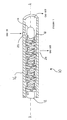
- FIG. 1 shows a device which may be used to sense the temperature of a gas flowing through a chamber.
- a thermocouple probe 10 has a longitudinal axis AA and comprises a thin elongate mineral-insulated thermocouple element 12 having a sensing tip 14.
- the thermocouple element 12 itself comprises a cylindrical outer jacket, typically of Inconel 600, containing at least one pair of thermocouple wires. The wires are joined together to form a thermocouple junction at the sensing tip 14, but are otherwise insulated from each other and from the outer sheath by magnesium oxide powder.
- the outer diameter of the thermocouple element 12 is typically 4.5mm, although smaller diameters are possible. For example, to enhance the speed of response, the diameter of the sensing tip 14 may be swaged down to about 2.0mm.
- thermocouple element 12 is disposed coaxially within a cylindrical protective sheath 16, which defines an annular space around the element.
- the sheath 16 is made of a material resistant to high temperatures, such as Nimonic 80 or Hastelloy X.
- the thermocouple element 12 is resiliently supported within the sheath 16, and held in coaxial alignment with it, by means of a helical member 18, which consists of a filament having a rectangular cross-section.
- the radial thickness of the filament is less than its width in the axial direction; and the radial thickness is also less than the radial separation between the thermocouple element 12 and the sheath 16.
- the helical member 18 is adapted to make alternate contact with the inner periphery of the sheath 16 and the outer periphery of the thermocouple element 12.
- the circumferential spacing of the contact areas is selected to give the desired support between the thermocouple element and the sheath.
- the contact areas spiral around the longitudinal axis of the probe 10 along the axial length of the helical member 18.
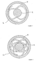
- the helical member 18 may comprise rippled or corrugated turns, so that it makes contact with both the sheath 16 and the thermocouple element 12, the maximum amplitude of the corrugations in a radial direction being at least as great as the radial separation between the sheath 16 and the element 12 ( Figure 2).
- a helical member 18 composed of a corrugated filament may be produced by wrapping a strip of material around a mandrel having the desired varying cross-sectional shape. The dimensions are chosen such that on assembly the thermocouple element 12 is an interference fit within the helical member 18, and the helical member is an interference fit within the sheath 16.
- the helical member 18 may comprise turns of elliptical cross-section ( Figure 3) which obviates the need for a corrugated filament.
- the elliptical turns are dimensioned such that along a major diameter the helical member is in contact with the sheath 16, and that along a minor diameter the helical member is in contact with the thermocouple element 12. Adjacent elliptical turns are angularly offset so that the contact areas spiral around the longitudinal axis of the probe 10.
- a helical member 18 having offset elliptical cross-sections may be produced by firstly wrapping a strip of material around a mandrel having an elliptical cross-section, and then twisting the resulting helical structure about its longitudinal axis to progressively offset adjacent elliptical turns.
- the successive contact areas with the sheath 16 are shown more than 180° apart, if the angle is measured following the sense of rotation around the helical member 18.
- the degree of twist imparted to the structure to offset adjacent elliptical turns may be such that successive contact points are less than 180° apart.
- the protective sheath 16 is provided with axially offset apertures 22, 24 which permit the gas flowing through the aforementioned chamber to pass over the sensing tip 14 of the thermocouple element.
- the apertures 22, 24 have elliptical cross-sections which are orientated such that the major diameters of the ellipses are aligned parallel to the longitudinal axis of the thermocouple probe 10.
- the extreme end of the sheath 16 adjacent the sensing tip 14 may be closed by a weld-on end cap (not shown).
- thermocouple element 12 may comprise two independent thermocouples, the first located at the sensing tip 14 of the probe 10 and the second located at about half way along the length of the element 12.
- two helical members 18 are employed, one on each side of the second (half-way) thermocouple junction.
- the sensing tip 14 actually protrudes slightly from the sheath 16 into the gas flow, and three apertures (one inlet and two outlet) are provided near the second junction to promote the desired fast response.
- the inlet aperture faces into the gas flow, while the exit apertures are circumferentially and axially offset and positioned just over 90° from the inlet aperture, so as to occupy areas of low pressure.
- thermocouple element 12 the sheath 16 and the helical member 18 are selected to have optimum properties for their particular roles. If desired, different materials having slightly different thermal expansion coefficients could be selected for these components since any resulting differential expansion in a longitudinal direction may be accommodated in the helical member 18.
Landscapes
- Physics & Mathematics (AREA)
- General Physics & Mathematics (AREA)
- Measuring Temperature Or Quantity Of Heat (AREA)
Claims (7)
- Sonde à thermocouple (10) servant à détecter la température d'un gaz qui s'écoule à travers une chambre, comprenant un élément de thermocouple allongé (12) disposé sensiblement coaxialement à l'intérieur d'une gaine cylindrique allongée (16) de manière qu'il existe une cavité autour de l'élément thermocouple, caractérisée en ce que l'élément de thermocouple est suspendu élastiquement à l'intérieur de la gaine par un élément hélicoïdal (18) agencé coaxialement avec l'élément de thermocouple et qui a une pluralité de spires de section non circulaire, de sorte que l'élément hélicoïdal est alternativement en contact avec la périphérie intérieure de la gaine et avec la périphérie extérieure de l'élément de thermocouple.
- Sonde à thermocouple (10) selon la revendication 1, dans laquelle l'élément hélicoïdal (18) a des spires de section sensiblement elliptique qui sont décalées angulairement, de sorte que les points de contact sont répartis circonférentiellement sur le tour de la périphérie intérieure de la gaine (16) et de la périphérie extérieure de l'élément de thermocouple (12) respectivement.
- Sonde à thermocouple (10) selon la revendication 1, dans laquelle l'élément hélicoïdal (18) est ondulé de manière que les extrémités radiales des ondulations produisent les point s de contact qui sont répartis circonférentiellement sur le tour de la périphérie intérieure de la gaine (16) et de la périphérie extérieure de l'élément de thermocouple (12) respectivement.
- Sonde à thermocouple (10) selon une quelconque des revendications précédentes, dans laquelle l'élément hélicoïdal (18) est constitué par un filament se section rectangulaire qui est utilisé de manière que l'épaisseur du filament, mesurée dans une direction radiale, soit inférieure à la largeur mesurée dans la direction axiale.
- Sonde à thermocouple (10) selon une quelconque des revendications précédentes dans laquelle la gaine (16) est faite d'un alliage à haute température choisi entre le nimonic et l'hastelloy.
- Sonde à thermocouple (10) selon une quelconque des revendications précédentes dans laquelle la gaine (16) a au moins deux ouvertures (22, 24) qui permettent au gaz dont il s'agit de capter la température de s'écouler sur l'élément de thermocouple (12).
- Sonde à thermocouple (10) selon la revendication 6 dans laquelle au moins une des ouvertures a une section elliptique qui est orientée de manière que son grand diamètre soit parallèle à l'axe longitudinal de la sonde.
Priority Applications (1)
| Application Number | Priority Date | Filing Date | Title |
|---|---|---|---|
| EP97103451A EP0785418B1 (fr) | 1992-10-30 | 1993-10-25 | Capteur à thermocouple |
Applications Claiming Priority (2)
| Application Number | Priority Date | Filing Date | Title |
|---|---|---|---|
| GB9222811 | 1992-10-30 | ||
| GB9222811A GB2272058B (en) | 1992-10-30 | 1992-10-30 | Thermocouple probe |
Related Child Applications (1)
| Application Number | Title | Priority Date | Filing Date |
|---|---|---|---|
| EP97103451A Division EP0785418B1 (fr) | 1992-10-30 | 1993-10-25 | Capteur à thermocouple |
Publications (2)
| Publication Number | Publication Date |
|---|---|
| EP0595579A1 EP0595579A1 (fr) | 1994-05-04 |
| EP0595579B1 true EP0595579B1 (fr) | 1998-01-07 |
Family
ID=10724304
Family Applications (2)
| Application Number | Title | Priority Date | Filing Date |
|---|---|---|---|
| EP93308481A Expired - Lifetime EP0595579B1 (fr) | 1992-10-30 | 1993-10-25 | Capteur à thermocouple |
| EP97103451A Expired - Lifetime EP0785418B1 (fr) | 1992-10-30 | 1993-10-25 | Capteur à thermocouple |
Family Applications After (1)
| Application Number | Title | Priority Date | Filing Date |
|---|---|---|---|
| EP97103451A Expired - Lifetime EP0785418B1 (fr) | 1992-10-30 | 1993-10-25 | Capteur à thermocouple |
Country Status (4)
| Country | Link |
|---|---|
| US (3) | US5423610A (fr) |
| EP (2) | EP0595579B1 (fr) |
| DE (2) | DE69316152T2 (fr) |
| GB (2) | GB2272058B (fr) |
Families Citing this family (17)
| Publication number | Priority date | Publication date | Assignee | Title |
|---|---|---|---|---|
| US6094904A (en) * | 1998-07-16 | 2000-08-01 | United Technologies Corporation | Fuel injector with a replaceable sensor |
| US6408705B1 (en) * | 2000-11-28 | 2002-06-25 | General Electric Company | Mounting block for a proximity probe used for measuring axial movement of a rotor |
| JP3749135B2 (ja) * | 2001-03-13 | 2006-02-22 | 横河電子機器株式会社 | 温度測定装置 |
| US6827486B2 (en) * | 2002-11-22 | 2004-12-07 | Welker Engineering Company | Temperature probe and insertion device |
| US6857776B2 (en) | 2002-12-12 | 2005-02-22 | Ametek, Inc. | Connectorized high-temperature thermocouple |
| US20040114666A1 (en) * | 2002-12-17 | 2004-06-17 | Hardwicke Canan Uslu | Temperature sensing structure, method of making the structure, gas turbine engine and method of controlling temperature |
| US7131768B2 (en) * | 2003-12-16 | 2006-11-07 | Harco Laboratories, Inc. | Extended temperature range EMF device |
| ES2378956T5 (es) | 2006-06-28 | 2019-10-09 | Medtronic Ardian Luxembourg | Sistemas para la neuromodulación renal térmicamente inducida |
| FR2924218B1 (fr) * | 2007-11-23 | 2010-03-19 | Commissariat Energie Atomique | Procede de mesure de la temperature surfacique interne d'un tube et dispositif associe |
| JP5198934B2 (ja) * | 2008-05-09 | 2013-05-15 | 日本特殊陶業株式会社 | 温度センサ |
| EP2386843B1 (fr) * | 2010-05-11 | 2016-08-03 | Innovatherm Prof. Dr. Leisenberg GmbH & Co. KG | Thermocouple |
| US20120023967A1 (en) * | 2010-07-30 | 2012-02-02 | Dede Brian C | Auxiliary power unit with hot section fire enclosure arrangement |
| GB2483931B (en) * | 2010-09-27 | 2015-12-23 | Endet Ltd | Combined fluid sampling and monitoring probe |
| US9086303B2 (en) | 2012-04-27 | 2015-07-21 | Rosemount Inc. | Vibration damper for sensor housing |
| DE102012012740A1 (de) * | 2012-06-26 | 2014-01-02 | Linde Ag | Temperaturmesseinrichtung mit Temperaturmesshülse zur Messung der Temperatur eines fließenden Mediums |
| US8858074B2 (en) * | 2012-07-16 | 2014-10-14 | United Technologies Corporation | Damped EGT probe |
| US9587993B2 (en) * | 2012-11-06 | 2017-03-07 | Rec Silicon Inc | Probe assembly for a fluid bed reactor |
Family Cites Families (22)
| Publication number | Priority date | Publication date | Assignee | Title |
|---|---|---|---|---|
| DE8175C (de) * | J. W. klinghammer in Braunschweig | Hepsometer, Apparat zur Führung des Kochprozesses beim Verdampfen im Vacuum | ||
| DD8175A (fr) * | ||||
| DE969571C (de) * | 1949-03-23 | 1958-06-19 | Siemens Ag | Verfahren zur Herstellung eines Messwiderstandes fuer Widerstandsthermometer mit einer auf einem duennwandigen Traeger elektrisch isoliert aufgebrachten Messwicklung |
| GB734702A (en) * | 1952-12-16 | 1955-08-03 | Rolls Royce | Improvements in measuring gas temperatures |
| GB1077876A (en) * | 1965-02-03 | 1967-08-02 | Mullard Ltd | Method and apparatus for mounting thermocouples |
| US3845706A (en) * | 1972-03-22 | 1974-11-05 | Bethlehem Steel Corp | Apparatus for continuously measuring temperature in a furnace |
| US3802926A (en) * | 1972-04-24 | 1974-04-09 | Corning Glass Works | Thermocouple with spaced electrically insulating sheaths |
| GB1386837A (en) * | 1972-06-27 | 1975-03-12 | Sangamo Weston | Thermocouple elements |
| US4001045A (en) * | 1975-03-03 | 1977-01-04 | Sangamo Weston Limited | Thermocouple |
| AU1645676A (en) * | 1975-08-05 | 1978-02-02 | Broken Hill Pty Co Ltd | Temperature probes |
| US3970481A (en) * | 1975-11-12 | 1976-07-20 | Tudor Technology, Inc. | Thermocouple |
| US4244221A (en) * | 1979-02-01 | 1981-01-13 | General Electric Company | Removable instrumentation probe |
| JPS58147622A (ja) * | 1982-02-27 | 1983-09-02 | Shuichi Nakagawa | 熱電対 |
| US4467134A (en) * | 1983-06-30 | 1984-08-21 | General Electric Company | Thermocouple with out-of-line aspiration holes |
| US4499330A (en) * | 1983-12-23 | 1985-02-12 | General Electric Company | Anti-vibration support for thermocouple tip |
| US4778538A (en) * | 1987-07-15 | 1988-10-18 | Westinghouse Electric Corp. | Dual temperature sensing device having twin well thermowell for dual resistance temperature detectors |
| FR2621120B1 (fr) * | 1987-09-24 | 1990-07-06 | Cyberexact | Capteur de mesure de temperature |
| US4999330A (en) * | 1988-03-22 | 1991-03-12 | Universite Du Quebec A Trois-Rivieres | High-density adsorbent and method of producing same |
| DE3927075A1 (de) * | 1989-08-16 | 1991-02-21 | Siemens Ag | Messanordnung fuer die ermittlung der temperatur einer eine rohrleitung durchstroemenden fluessigkeit |
| LU87694A1 (fr) * | 1990-03-07 | 1991-10-08 | Wurth Paul Sa | Sonde de prise d'echantillons gazeux et de mesures thermiques au-dessus de la surface de chargement d'un four a cuve |
| DE4014502C2 (de) * | 1990-05-07 | 1998-09-03 | Bayerische Motoren Werke Ag | Verfahren zum Einbau eines Sensors in eine formgepreßte Dichtung |
| US5141335A (en) * | 1991-03-15 | 1992-08-25 | Alltemp Sensors Inc. | Thermocouple connector |
-
1992
- 1992-10-30 GB GB9222811A patent/GB2272058B/en not_active Expired - Lifetime
- 1992-10-30 GB GB9611479A patent/GB2300270B/en not_active Expired - Lifetime
-
1993
- 1993-10-25 DE DE69316152T patent/DE69316152T2/de not_active Expired - Lifetime
- 1993-10-25 EP EP93308481A patent/EP0595579B1/fr not_active Expired - Lifetime
- 1993-10-25 DE DE69332613T patent/DE69332613T2/de not_active Expired - Lifetime
- 1993-10-25 EP EP97103451A patent/EP0785418B1/fr not_active Expired - Lifetime
- 1993-10-26 US US08/142,184 patent/US5423610A/en not_active Expired - Lifetime
-
1994
- 1994-12-09 US US08/353,102 patent/US5678926A/en not_active Ceased
-
1998
- 1998-02-17 US US09/024,743 patent/USRE36285E/en not_active Expired - Lifetime
Also Published As
| Publication number | Publication date |
|---|---|
| DE69332613D1 (de) | 2003-02-06 |
| GB2272058A (en) | 1994-05-04 |
| DE69316152T2 (de) | 1998-07-16 |
| EP0785418A2 (fr) | 1997-07-23 |
| DE69332613T2 (de) | 2003-09-11 |
| US5423610A (en) | 1995-06-13 |
| GB2300270B (en) | 1997-01-29 |
| DE69316152D1 (de) | 1998-02-12 |
| GB2300270A (en) | 1996-10-30 |
| USRE36285E (en) | 1999-08-31 |
| EP0785418B1 (fr) | 2003-01-02 |
| US5678926A (en) | 1997-10-21 |
| GB9611479D0 (en) | 1996-08-07 |
| EP0595579A1 (fr) | 1994-05-04 |
| GB9222811D0 (en) | 1992-12-09 |
| EP0785418A3 (fr) | 1997-07-30 |
| GB2272058B (en) | 1997-01-29 |
Similar Documents
| Publication | Publication Date | Title |
|---|---|---|
| EP0595579B1 (fr) | Capteur à thermocouple | |
| US4991976A (en) | Temperature sensor probe apparatus and method for improving time response | |
| US5662418A (en) | High temperature probe | |
| US7997795B2 (en) | Temperature sensors and methods of manufacture thereof | |
| USRE35674E (en) | Thermocouple with out-of-line aspiration holes | |
| US6039325A (en) | Resilient braided rope seal | |
| US4865462A (en) | Thermocouples | |
| EP1466148B1 (fr) | Thermocouple de type rateau | |
| CN1090316C (zh) | 高温探头 | |
| FR2967257A1 (fr) | Dispositif de protection de surchauffe de turbocompresseur et procede pour sa fabrication | |
| JPS582606B2 (ja) | 検知装置 | |
| EP0546786A1 (fr) | Couples thermo-électriques | |
| CN109000814B (zh) | 浮动导体封装 | |
| WO2015017035A1 (fr) | Capteur de température à réponse rapide à rtd renfermant un polyimide | |
| US3485101A (en) | Continuously supported sensor | |
| GB2224074A (en) | Glow plug | |
| SE506670C2 (sv) | Fästarrangemang för katalysatorer | |
| JP7319685B2 (ja) | 熱電対 | |
| EP0989393A2 (fr) | Thermocouple et procédé de fabrication | |
| EP3916369B1 (fr) | Capteur thermique et procédé de fabrication | |
| US4092177A (en) | Thermopile construction | |
| US20220268610A1 (en) | Immersion probes and related methods | |
| CN213586318U (zh) | 一种发热组件 | |
| JPH07174637A (ja) | 熱電対装置 | |
| JPS5848847B2 (ja) | 高温度検出器 |
Legal Events
| Date | Code | Title | Description |
|---|---|---|---|
| PUAI | Public reference made under article 153(3) epc to a published international application that has entered the european phase |
Free format text: ORIGINAL CODE: 0009012 |
|
| AK | Designated contracting states |
Kind code of ref document: A1 Designated state(s): DE FR IT |
|
| RAP1 | Party data changed (applicant data changed or rights of an application transferred) |
Owner name: WESTON AEROSPACE LIMITED |
|
| 17P | Request for examination filed |
Effective date: 19941024 |
|
| RAP1 | Party data changed (applicant data changed or rights of an application transferred) |
Owner name: SOLARTRON GROUP LIMITED |
|
| 17Q | First examination report despatched |
Effective date: 19960618 |
|
| RAP3 | Party data changed (applicant data changed or rights of an application transferred) |
Owner name: SOLARTRON GROUP LIMITED |
|
| GRAG | Despatch of communication of intention to grant |
Free format text: ORIGINAL CODE: EPIDOS AGRA |
|
| GRAG | Despatch of communication of intention to grant |
Free format text: ORIGINAL CODE: EPIDOS AGRA |
|
| GRAH | Despatch of communication of intention to grant a patent |
Free format text: ORIGINAL CODE: EPIDOS IGRA |
|
| GRAH | Despatch of communication of intention to grant a patent |
Free format text: ORIGINAL CODE: EPIDOS IGRA |
|
| GRAA | (expected) grant |
Free format text: ORIGINAL CODE: 0009210 |
|
| ITF | It: translation for a ep patent filed |
Owner name: BARZANO' E ZANARDO MILANO S.P.A. |
|
| AK | Designated contracting states |
Kind code of ref document: B1 Designated state(s): DE FR IT |
|
| XX | Miscellaneous (additional remarks) |
Free format text: TEILANMELDUNG 97103451.7 EINGEREICHT AM 03/03/97. |
|
| REF | Corresponds to: |
Ref document number: 69316152 Country of ref document: DE Date of ref document: 19980212 |
|
| ET | Fr: translation filed | ||
| PLBE | No opposition filed within time limit |
Free format text: ORIGINAL CODE: 0009261 |
|
| STAA | Information on the status of an ep patent application or granted ep patent |
Free format text: STATUS: NO OPPOSITION FILED WITHIN TIME LIMIT |
|
| 26N | No opposition filed | ||
| REG | Reference to a national code |
Ref country code: FR Ref legal event code: TP Ref country code: FR Ref legal event code: CD Ref country code: FR Ref legal event code: CA |
|
| PGFP | Annual fee paid to national office [announced via postgrant information from national office to epo] |
Ref country code: DE Payment date: 20121017 Year of fee payment: 20 Ref country code: FR Payment date: 20121018 Year of fee payment: 20 |
|
| PGFP | Annual fee paid to national office [announced via postgrant information from national office to epo] |
Ref country code: IT Payment date: 20121013 Year of fee payment: 20 |
|
| REG | Reference to a national code |
Ref country code: DE Ref legal event code: R071 Ref document number: 69316152 Country of ref document: DE |
|
| PG25 | Lapsed in a contracting state [announced via postgrant information from national office to epo] |
Ref country code: DE Free format text: LAPSE BECAUSE OF EXPIRATION OF PROTECTION Effective date: 20131026 |