EP0594567B1 - Sieb - Google Patents
Sieb Download PDFInfo
- Publication number
- EP0594567B1 EP0594567B1 EP90910816A EP90910816A EP0594567B1 EP 0594567 B1 EP0594567 B1 EP 0594567B1 EP 90910816 A EP90910816 A EP 90910816A EP 90910816 A EP90910816 A EP 90910816A EP 0594567 B1 EP0594567 B1 EP 0594567B1
- Authority
- EP
- European Patent Office
- Prior art keywords
- screen
- bellows
- fluid
- pipe
- opening
- Prior art date
- Legal status (The legal status is an assumption and is not a legal conclusion. Google has not performed a legal analysis and makes no representation as to the accuracy of the status listed.)
- Expired - Lifetime
Links
- 239000012530 fluid Substances 0.000 claims abstract description 82
- 239000011343 solid material Substances 0.000 claims abstract description 3
- 238000011001 backwashing Methods 0.000 claims description 30
- 239000000463 material Substances 0.000 claims description 11
- 238000004891 communication Methods 0.000 description 19
- 230000000694 effects Effects 0.000 description 15
- 238000001914 filtration Methods 0.000 description 7
- 239000007788 liquid Substances 0.000 description 4
- 238000000034 method Methods 0.000 description 4
- 239000002245 particle Substances 0.000 description 4
- 238000010276 construction Methods 0.000 description 3
- 239000000356 contaminant Substances 0.000 description 3
- XLYOFNOQVPJJNP-UHFFFAOYSA-N water Substances O XLYOFNOQVPJJNP-UHFFFAOYSA-N 0.000 description 3
- 238000004519 manufacturing process Methods 0.000 description 2
- 239000011435 rock Substances 0.000 description 2
- 239000013535 sea water Substances 0.000 description 2
- 229920002430 Fibre-reinforced plastic Polymers 0.000 description 1
- 239000002253 acid Substances 0.000 description 1
- 230000009471 action Effects 0.000 description 1
- 230000004075 alteration Effects 0.000 description 1
- 230000009286 beneficial effect Effects 0.000 description 1
- 230000008901 benefit Effects 0.000 description 1
- 239000013043 chemical agent Substances 0.000 description 1
- 238000007385 chemical modification Methods 0.000 description 1
- 238000007599 discharging Methods 0.000 description 1
- 239000011151 fibre-reinforced plastic Substances 0.000 description 1
- 239000002184 metal Substances 0.000 description 1
- 230000004048 modification Effects 0.000 description 1
- 238000012986 modification Methods 0.000 description 1
- 230000000737 periodic effect Effects 0.000 description 1
- 239000003208 petroleum Substances 0.000 description 1
- 239000011148 porous material Substances 0.000 description 1
- 230000008569 process Effects 0.000 description 1
- 238000005086 pumping Methods 0.000 description 1
- 239000004576 sand Substances 0.000 description 1
- 239000007787 solid Substances 0.000 description 1
- 239000002904 solvent Substances 0.000 description 1
- 238000005507 spraying Methods 0.000 description 1
- 238000011144 upstream manufacturing Methods 0.000 description 1
- 238000004804 winding Methods 0.000 description 1
Images


Classifications
-
- B—PERFORMING OPERATIONS; TRANSPORTING
- B01—PHYSICAL OR CHEMICAL PROCESSES OR APPARATUS IN GENERAL
- B01D—SEPARATION
- B01D29/00—Filters with filtering elements stationary during filtration, e.g. pressure or suction filters, not covered by groups B01D24/00 - B01D27/00; Filtering elements therefor
- B01D29/11—Filters with filtering elements stationary during filtration, e.g. pressure or suction filters, not covered by groups B01D24/00 - B01D27/00; Filtering elements therefor with bag, cage, hose, tube, sleeve or like filtering elements
- B01D29/114—Filters with filtering elements stationary during filtration, e.g. pressure or suction filters, not covered by groups B01D24/00 - B01D27/00; Filtering elements therefor with bag, cage, hose, tube, sleeve or like filtering elements arranged for inward flow filtration
-
- B—PERFORMING OPERATIONS; TRANSPORTING
- B01—PHYSICAL OR CHEMICAL PROCESSES OR APPARATUS IN GENERAL
- B01D—SEPARATION
- B01D29/00—Filters with filtering elements stationary during filtration, e.g. pressure or suction filters, not covered by groups B01D24/00 - B01D27/00; Filtering elements therefor
- B01D29/62—Regenerating the filter material in the filter
- B01D29/66—Regenerating the filter material in the filter by flushing, e.g. counter-current air-bumps
- B01D29/663—Regenerating the filter material in the filter by flushing, e.g. counter-current air-bumps by using membranes
-
- B—PERFORMING OPERATIONS; TRANSPORTING
- B01—PHYSICAL OR CHEMICAL PROCESSES OR APPARATUS IN GENERAL
- B01D—SEPARATION
- B01D29/00—Filters with filtering elements stationary during filtration, e.g. pressure or suction filters, not covered by groups B01D24/00 - B01D27/00; Filtering elements therefor
- B01D29/88—Filters with filtering elements stationary during filtration, e.g. pressure or suction filters, not covered by groups B01D24/00 - B01D27/00; Filtering elements therefor having feed or discharge devices
- B01D29/94—Filters with filtering elements stationary during filtration, e.g. pressure or suction filters, not covered by groups B01D24/00 - B01D27/00; Filtering elements therefor having feed or discharge devices for discharging the filter cake, e.g. chutes
- B01D29/945—Filters with filtering elements stationary during filtration, e.g. pressure or suction filters, not covered by groups B01D24/00 - B01D27/00; Filtering elements therefor having feed or discharge devices for discharging the filter cake, e.g. chutes for continuously discharging concentrated liquid
Definitions
- This invention relates to strainers which can be used for the removal of solid or liquid particles or other contaminating material from a fluid, for example plankton from seawater, particles from a gas, or sand from a liquid.
- the particles may be of various shapes and sizes e.g. from several microns to several millimetres.
- Water is used to maintain the pressure of liquid in natural submarine petroleum reservoirs but many of the reservoirs are in the form of porous rocks, and plankton can, if permitted to enter the rocks, choke the small pores thereby making it more difficult to inject water into the reservoir. For this reason it is desirable to employ water from which contaminants such as plankton have been removed.
- Strainers usually have one or more openings and the fluid, from which the contaminating material is to be removed, passes through the opening(s).
- the material that is prevented from passing through the opening(s) may be too large to fit through the opening(s), or may be prevented from passing therethrough by some other means, for example an electrostatic force.
- Fluid that has been derived from contaminated fluid, by passing the latter through the opening(s) of a strainer, may be called a decontaminated fluid.
- a phenomenon which occurs with many strainers is the blockage of the opening(s) by the residue of the particles or other entrained contaminating material which have been filtered or strained out of the fluid.
- the blockage of the opening(s) will usually restrict the flow of fluid through the opening(s) and increase the pressure difference between the contaminated fluid and decontaminated fluid.
- the removal of plankton from seawater it may be beneficial to remove the residue from the vicinity of the opening(s). This can enable a greater flow of fluid to pass through the opening(s), or cause a decrease in any potential build-up of pressure difference between the contaminated fluid and the decontaminated fluid.
- the removal of the residue may be effected on a continuous basis or may be carried out on a periodic basis.
- FR-A-2289222 discloses a strainer provided with a screen having one or more restricted opening(s), with provision for a fluid contaminated by entrained solid material to flow in normal use through the screen in one direction, whereby contaminating material of more than a predetermined size is filtered off because of its inability to pass through the opening(s), there being inflatable and deflatable bellows means in the vicinity of the screen and capable upon inflation of causing fluid to pass through the opening(s) in the screen in a direction opposite to the one direction so as to dislodge residue trapped by, and held in the vicinity of, the restricted opening(s); and, according to the invention, such a strainer is characterised in that the bellows means is arranged, upon partial inflation, to abut against the screen at spaced positions forming thereby between the spaced positions a plurality of screen sections which are separated from each other, and, upon further inflation, to pump backwashing fluid through these screen sections.
- bellows means which are responsible, at least partially, for the desired backwash effect to clean the strainer according to the present invention, e.g. by acting as a pumping means either to push or to draw fluid through the opening(s).
- the bellows means may comprise a row of bellows, each alternate set of which are inflatable separately from the intervening set. One alternate set of the bellows may then be inflated to close off respective sections of the screen, and thereby isolating intervening sections, which may subsequently be positively backwashed by inflation of the intervening set of bellows.
- the sets of bellows may, in a subsequent step, be inflated in reverse order to backwash positively the other screen sections.
- the bellows means or the screen may be so formed with ribs that, upon partial inflation, the ribs abut the screen at the spaced positions, further inflation causing the bellows means to deflect between the spaced positions.
- the screen could take the form of a wall, which could be planar or substantially cylindrical, for example provided with many small openings.
- the screen could include a plurality of parallel members disposed so as to form a cylinder, the members being sufficiently close together to form between pairs of members the desired restricted openings.
- a single continuous helical opening can be defined by the winding of a suitable wire around parallel supports.
- the one direction may be radially outwardly, but is preferably radially inwardly, the bellows means being within the screen and being inflatable for backwashing.
- FIG. 1 there is shown a strainer which has a cylindrical side wall 2 incorporating a screen 3 provided with openings.
- the cylindrical wall 2 together with associated end walls 4 and 5, define a chamber 6.
- Projecting into the chamber 6 is an inner tube 7 which is coaxially disposed with respect to the cylindrical side wall 2, the inner tube 7 defining an inner duct 8.
- an outer tube 9 of greater diameter Coaxially disposed with respect to the inner tube 7 is an outer tube 9 of greater diameter, an outer duct 10 being defined between the inner tube 7 and the outer tube 9.
- the inner and outer tubes 7 and 9 are open at one end and sealed at the opposite end which is located within the chamber.
- Providing communication between the bellows 11 and 13 on the one hand and the outer duct 10 on the other hand are radial conduits 15; and providing communication between the interior of the bellows 12 and 14 on the one hand and the inner duct 8 on the other hand are radial conduits 16.
- the bellows can adopt the deflated position, as shown by bellows 11 and 13, or an inflated condition as shown by the bellows 12 and 14.
- an outlet pipe 17 Disposed in the end wall 5 is an outlet pipe 17 in which is located a ball valve 18.
- the ball valve 18 When it is desired to remove residue from the exterior of the screen 3, the ball valve 18 is closed, and fluid under increased pressure (i.e. greater than that outside the screen 3) is introduced into the inner duct 8 and, via the conduits 16, into the bellows 12 and 14. This causes some backwashing effect through the screen 3. Thereafter, fluid, for example, a gas, under pressure is introduced into the outer duct 10 and, via the conduits 15, into the bellows 11 and 13 thereby expelling the decontaminated fluid which is to serve as the backwashing fluid through those regions of the screen 3 between the already inflated bellows 12 and 14, and between bellows 12 and end wall 4.
- fluid for example, a gas
- next backwash cycle instead of first inflating the bellows 12 and 14, prior to the inflation of the bellows 11 and 13, it is possible to reverse the order so that initially the bellows 11 and 13 are inflated and thereafter the bellows 12 and 14 are inflated.
- strainer shown in Figure 1 could be adapted in many different ways.
- the bellows could be mounted on the outside of the screen 3 within a suitable chamber and the number of bellows could be varied.
- the screen 3, instead of being cylindrical, could be of some other shape, such as a flat screen.
- the bellows may be made of any suitable material; for example, the bellows may be made of a metal or may be made of a fibre-reinforced plastic material, or a rubber material, provided that the material is suitable for the duty to which it will be subjected during the back-washing modes of the strainer.
- the strainer of the type illustrated in Figure 1 may be operated in parallel with, or in series with, other straining devices.
- the strainer as illustrated in Figure 1 may have any appropriate auxiliary equipment associated with it, such as instrumentation, gas reservoirs, accumulators, valves, pressure piping and pressure vessels.
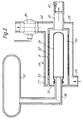
- FIG. 2 of the drawings shows a construction which is not in accordance with the present invention.
- the screen is no longer the outermost component, but the bellows is still on the inside of the screen.
- a pressure vessel generally indicated by the reference numeral 26, the vessel having a cylindrical side wall 27 and two end walls 28 and 29.
- Located coaxially within the vessel 26 is a cylindrical wall 30 which extends from the end wall 28 of the vessel 26.
- the cylindrical wall 30 is provided with a screen 31, and there is thus defined between the cylindrical wall 30 and screen 31 on the one hand and the cylindrical side wall 27 on the other hand an annular chamber 32.
- the vessel 26 is provided with an inlet pipe 33 which communicates with one end region of the annular chamber 32, and is also provided with a pipe 34 communicating with the opposite end region of the annular chamber 32, the pipe 34 serving as an outlet during backwashing.
- the pipe 34 is provided with a ball valve 35.
- a pipe 36 Entering the vessel 26 through the end wall 28 is a pipe 36 which leads from a reservoir 37 containing fluid under pressure.
- the pipe 36 is of smaller diameter than the cylindrical wall 30 and the pipe 36 leads to a bellows 38 located coaxially within the vessel 26, and within the cylindrical wall 30 and screen 31. There is thus defined a generally annular zone 39 between the bellows 38 and the screen 31. That zone 39 communicates via a pipe 40 which passes through the end wall 29 and leads to a non-return valve 42.
- the equipment of Figure 2 is operated as follows.
- the ball valve 35 is closed and contaminated fluid is passed through the pipe 33 to the annular chamber 32.
- the fluid passes through the screen 31 and decontaminated fluid leaves through the pipe 40 and passes through the non-return valve 42.
- valve 42 during the filtering mode this valve is open whereas, during the backwashing mode, the fall in pressure of the fluid within the annular zone 39 causes the valve 42 to close or to close substantially.
- valve 35 is closed which results in an increase in pressure in the annular chamber 32 and then in the annular zone 39, thereby causing the inflated bellows 38 to deflate.
- the contaminated fluid can then continue to flow through the screen 31 with the contaminants being removed by the screen 31 and with the resulting decontaminated fluid passing into the annular zone 39 and from there via the pipe 40 and the valve 42 to a suitable collection point.
- a pressure containing vessel 50 which has a cylindrical side wall 51 and two opposite end walls 52 and 53.
- a cylindrical wall 54 Coaxially disposed within the vessel 50 is a cylindrical wall 54 provided with a screen 55 provided with openings. Defined between the cylindrical side wall 51 on the one hand and the cylindrical wall 54 and screen 55 on the other hand is an annular chamber 56.
- an outer pipe 57 Coaxially located with the vessel 50 and of smaller diameter than the cylindrical wall 54 is an outer pipe 57 and, within that, and spaced therefrom, an inner pipe 58.
- the outer pipe 57 and inner pipe 58 are closed at one end but pass through the end wall 52 of the vessel 50 at their opposite end region to the closed end.
- annular chamber 59 Defined between the outer pipe 57 on the one hand and the cylindrical wall 54 and screen 55 on the other hand is an annular chamber 59 in which are located a row of six annular bellows 60, 61, 62, 63, 64 and 65.
- the equipment also includes an inlet pipe 66 for introducing decontaminated fluid; the inlet pipe 66 has a first branch 67 in which is located a ball valve 68, and also has a second branch 69 in which is located a restriction 70.
- the first and second branches 67 and 69 open into one end region of annular chamber 56.
- an outlet pipe 71 for discharging decontaminated fluid Communicating with the annular chamber 59 at that end thereof remote from the end wall 52 and adjacent the end wall 53 is an outlet pipe 71 for discharging decontaminated fluid, the outlet pipe 71 being provided with a ball valve 72.
- the outer pipe 57 is provided with ducts 75 which communicate with the bellows 61, 63 and 65; and the inner pipe 58 is provided with ducts 76 which communicate with bellows 60, 62 and 64.
- the outer pipe 57 in a region externally of the end wall 52 of the vessel 50, communicates with a pipe 77 which leads from a valve 78 which, in addition to communicating with the pipe 77, communicates with a duct 79 and with a pipe 80 which, in turn, communicates with a valve 81.
- the valve 81 in addition to communicating with the pipe 80, communicates with a pipe 82 and a pipe 83 which leads to a further pipe 84.
- the inner pipe 58 in a region externally of the end wall 52, communicates with a pipe 85 which leads from a valve 86.
- the valve 86 in addition to communicating with the pipe 85, communicates with a duct 87 and with a pipe 88 which, in turn, communicates with another valve 89.
- the valve 89 in addition to communicating with the pipe 88, communicates with a pipe 90 and also with another region of the pipe 83.
- the valves 68, 72 and 74 can be moved from the closed position to the open position and vice versa.
- the four valves 78, 81, 86 and 89 are each designed so as to prevent communication altogether between the three pipes or ducts associated with the respective valves, but can be operated so as to permit communication between two, but not all three, of the respective associated pipes or ducts.
- valve 78 will normally be positioned to provide communication between the pipes 77 and 80, or between the pipe 77 and the duct 79.
- valve 86 will normally be positioned to provide communication between the pipes 85 and 88, or between the pipe 85 and the duct 87.
- the valve 81 will normally be operated to provide communication between the pipe 80 and the pipe 82, or between the pipe 80 and the pipe 83.
- the valve 89 will normally be positioned so as to provide communication between the pipe 88 and the pipe 90, or between the pipe 88 and pipe 83.
- the pipes 82 and 90 can be associated with a source of fluid at a pressure A.
- the pipe 84 can be associated with a source of fluid at a pressure B.
- the ducts 79 and 87 can be associated with fluid at a pressure C, which could be atmospheric pressure.
- the pipe 73, downstream of the valve 74 can discharge at a pressure D.
- the pipe 66 receives contaminated fluid at a pressure E.
- Contaminated fluid enters the pipe 66 with the majority passing along the first branch 67 but a small amount passing along the second branch 69, into the annular chamber 56.
- the fluid then passes through the openings in the screen 55 with the contaminant residue collecting on the exterior of the screen 55.
- the decontaminated fluid passes into the chamber 59 and, from there, through the pipe 71 and valve 72 to the discharge point.
- valves 68 and 72 When it is time to effect backwashing, the valves 68 and 72 are closed, and the valve 74 is opened.
- the second branch 69 with its restriction 70 nonetheless permits a small amount of contaminated fluid to continue to enter the annular chamber 56 so as to remove residue which is dislodged from the screen 55 during the backwashing, and to effect its removal through the pipe 73 and valve 74.
- valve 86 is operated so as to effect communication between the pipes 85 and 88 and the valve 89, if not already correctly operated, is operated so as to effect communication between the pipe 88 and the pipe 90, thus permitting fluid at pressure A to pass through the pipes 90, 88, 85 and 58, and then through the ducts 76 so as to inflate the bellows 60, 62 and 64, thereby partially effecting the backwashing as decontaminated fluid within the annular chamber 59 is forced back through the screen 55 into the annular chamber 56.
- valve 78 is operated to effect communication between the pipes 77 and 80 and the valve 81, if not already in the correct position, is operated to effect communication between the pipes 80 and 83, whereby fluid at the pressure B passes through the pipes 84, 83, 80, 77 and 57 to the ducts 75, thereby causing the bellows 61, 63 and 65 to inflate, thereby effecting backwashing in different zones of the screen 55.
- valves 78 and 86 are operated so as to effect communication between the pipe 77 and the duct 79 and between the pipe 85 and the duct 87, thereby permitting the pressure within the interior of the bellows 60 to 65 to fall to pressure C, thus allowing the bellows to deflate, at least partially. This will cause some contaminated fluid to be drawn through the screen 55 with the residue remaining on the exterior so that the annular chamber 59 is again full of decontaminated fluid.
- the backwashing exercise is repeated but with the bellows 61, 63 and 65 first being inflated at the higher pressure A and thereafter the other bellows 60, 62 and 64 being inflated at the high, but nonetheless lower, pressure B.
- This is effected by operating valve 81 so as to cause communication between pipes 82 and 80 and operating valve 78 so as to cause communication between pipes 80 and 77, whereby fluid at pressure A can communicate with the interior of the bellows 61, 63 and 65.
- the valve 89 is operated so as to cause communication between the pipes 83 and 88 and the valve 86 is operated so as to cause communication between the pipes 88 and 85, whereby fluid at pressure B can enter the bellows 60, 62 and 64.
- valves 78 and 86 are operated so as to permit communication between the pipe 77 and duct 79 and between the pipe 85 and duct 87, thereby allowing the high pressure within the bellows 60 to 65 to fall, thus permitting the bellows to deflate, at least partially.
- valves 68 and 72 are opened and the valve 74 is closed.
- the full filtering mode is resumed.
- inflating bellows alternatively as in the Figures 1 and 3 examples is that an annular isolated zone is formed between two spaced apart bellows so that an intermediate bellows can have an effective backwashing effect with the fluid being unable to escape except through the openings in the screen opposite the intermediate bellows.
- a bellows 91 which has a series of annular rings 92 of reduced wall thickness.
- the bellows When the bellows is initially inflated from the position shown in full lines, the bellows expands preferentially at the rings 92 to form outwardly protruding annular ribs 93 which, as the bellows continues to expand radially, abut and form annular lines of seal against the screen 94. This isolates annular sections of the screen from one another.
- the portions between the ribs 93 expand outwardly towards and into, or nearly into, contact with the screen, thereby ensuring positive backwashing of each section of the screen.
- the bellows 91 is replaced by a bellows 91A which is profiled with preformed ribs 93A.
- the bellows could be an unprofiled cylinder and the screen profiled with inwardly projecting annular ribs to seal against the bellows as it is partially inflated.
Landscapes
- Chemical & Material Sciences (AREA)
- Chemical Kinetics & Catalysis (AREA)
- Separation Using Semi-Permeable Membranes (AREA)
- Centrifugal Separators (AREA)
- Glass Compositions (AREA)
- Filtering Of Dispersed Particles In Gases (AREA)
- Silicates, Zeolites, And Molecular Sieves (AREA)
- Combined Means For Separation Of Solids (AREA)
- Pharmaceuticals Containing Other Organic And Inorganic Compounds (AREA)
- Orthopedics, Nursing, And Contraception (AREA)
- External Artificial Organs (AREA)
- Filtration Of Liquid (AREA)
- Fluid-Pressure Circuits (AREA)
- Control Of Throttle Valves Provided In The Intake System Or In The Exhaust System (AREA)
Claims (5)
- Filter, welcher mit einem Sieb (3, 31, 55, 94) versehen ist, das eine oder mehrere begrenzte Öffnung(en) hat, wobei Vorkehrungen getroffen sind, daß bei normaler Verwendung ein durch mitgerissene Feststoffe verunreinigtes Fluid in einer Richtung durch das Sieb strömt, wodurch verunreinigendes Material, das eine vorbestimmte Größe überschreitet, herausgefiltert wird, weil es nicht durch die Öffnung(en) passieren kann, und eine Balgeinrichtung (11-14;38;60-65;91;91A) in der Nähe des sieben angeordnet ist, die aufgeblasen und wieder entleert werden kann, und beim Aufblasen in der Lage ist, zu bewirken, daß Fluid durch die Öffnungen im Sieb in einer der einen Richtung entgegengesetzten Richtung hindurchströmt, so daß in der begrenzten Öffnung (den begrenzten Öffnungen) und in deren Nähe festgesetzte Ablagerungen von dort entfernt werden, dadurch gekennzeichnet, daß die Balgeinrichtung so angeordnet ist, daß sie bei teilweisem Aufblasen an voneinander entfernten Positionen gegen das Sieb Zu liegen kommt, dadurch zwischen den voneinander entfernten Positionen mehrere voneinander getrennte Siebabschnitte bildet, und bei fortschreitendem Aufblasen Rückspülfluid durch diese Abschnitte pumpt.
- Filter nach Anspruch 1, bei dem die Balgeinrichtung eine Reihe von Bälgen umfaßt, von denen jeder abwechselnde Satz (11,13;60,62,64) separat vom dazwischenliegenden Satz (12,14;61,63,65) aufgeblasen werden kann.
- Filter nach Anspruch 1, bei dem die Balgeinrichtung oder das Sieb so mit Rippen (93) versehen ist, daß bei teilweisem Aufblasen die Balgeinrichtung bei den Rippen an den voneinander entfernten Positionen gegen das Sieb Zu liegen kommt, und ein fortschreitendes Aufblasen bewirkt, daß die Balgeinrichtung sich durchbiegt und in Kontakt, oder annähernd in Kontakt mit den Siebbereichen kommt, die sich zwischen den voneinander entfernten Positionen befinden.
- Filter nach einem der vorstehenden Ansprüche, bei dem das Sieb (3;31;55;94) im wesentlichen zylindrisch ist, und die Balgeinrichtung (11-14;38;60-65;91) sich im Inneren des Siebs befindet und zum Rückspülen radial nach außen aufblasbar ist.
- Filter nach Anspruch 4, bei dem jeder Teil des Siebs zwischen den voneinander entfernten Positionen ringförmig ist.
Applications Claiming Priority (3)
| Application Number | Priority Date | Filing Date | Title |
|---|---|---|---|
| GB898918006A GB8918006D0 (en) | 1989-08-07 | 1989-08-07 | Strainer |
| GB8918006 | 1989-08-07 | ||
| PCT/GB1990/001127 WO1991001790A1 (en) | 1989-08-07 | 1990-07-23 | Strainer |
Publications (2)
| Publication Number | Publication Date |
|---|---|
| EP0594567A1 EP0594567A1 (de) | 1994-05-04 |
| EP0594567B1 true EP0594567B1 (de) | 1995-05-03 |
Family
ID=10661275
Family Applications (1)
| Application Number | Title | Priority Date | Filing Date |
|---|---|---|---|
| EP90910816A Expired - Lifetime EP0594567B1 (de) | 1989-08-07 | 1990-07-23 | Sieb |
Country Status (10)
| Country | Link |
|---|---|
| US (1) | US5238566A (de) |
| EP (1) | EP0594567B1 (de) |
| AT (1) | ATE121963T1 (de) |
| AU (1) | AU630995B2 (de) |
| BR (1) | BR9007581A (de) |
| CA (1) | CA2064586A1 (de) |
| DE (1) | DE69019171D1 (de) |
| GB (1) | GB8918006D0 (de) |
| IN (1) | IN176807B (de) |
| WO (1) | WO1991001790A1 (de) |
Families Citing this family (2)
| Publication number | Priority date | Publication date | Assignee | Title |
|---|---|---|---|---|
| FR2711076B1 (fr) * | 1993-10-13 | 1995-12-08 | Robatel Slpi | Dispositif étanche et déformable élastiquement pour le débatissage de la couche résiduelle. |
| EP1424119A3 (de) * | 2002-11-29 | 2004-06-16 | Taisei Kogyo Co., Ltd. | Filter mit Reinigungsvorrichtung |
Family Cites Families (4)
| Publication number | Priority date | Publication date | Assignee | Title |
|---|---|---|---|---|
| US2312999A (en) * | 1938-12-23 | 1943-03-02 | Langen Lambertus Hendrik De | Filter for separating solids from liquids |
| FR1276086A (fr) * | 1960-10-04 | 1961-11-17 | Arras Maxei | Perfectionnements apportés aux moyens pour assurer le nettoyage des filtres |
| FR2289222A1 (fr) * | 1974-10-30 | 1976-05-28 | Achard Picard Jean | Filtre sous pression a decolmatage pneumatique |
| US3994810A (en) * | 1975-07-28 | 1976-11-30 | Brunswick Corporation | Onstream backflush filter |
-
1989
- 1989-08-07 GB GB898918006A patent/GB8918006D0/en active Pending
-
1990
- 1990-07-23 BR BR909007581A patent/BR9007581A/pt not_active Application Discontinuation
- 1990-07-23 US US07/829,066 patent/US5238566A/en not_active Expired - Fee Related
- 1990-07-23 DE DE69019171T patent/DE69019171D1/de not_active Expired - Lifetime
- 1990-07-23 AT AT90910816T patent/ATE121963T1/de not_active IP Right Cessation
- 1990-07-23 WO PCT/GB1990/001127 patent/WO1991001790A1/en not_active Ceased
- 1990-07-23 EP EP90910816A patent/EP0594567B1/de not_active Expired - Lifetime
- 1990-07-23 CA CA002064586A patent/CA2064586A1/en not_active Abandoned
- 1990-07-23 AU AU60573/90A patent/AU630995B2/en not_active Ceased
- 1990-07-31 IN IN622MA1990 patent/IN176807B/en unknown
Also Published As
| Publication number | Publication date |
|---|---|
| DE69019171D1 (de) | 1995-06-08 |
| ATE121963T1 (de) | 1995-05-15 |
| WO1991001790A1 (en) | 1991-02-21 |
| IN176807B (de) | 1996-09-14 |
| AU630995B2 (en) | 1992-11-12 |
| EP0594567A1 (de) | 1994-05-04 |
| CA2064586A1 (en) | 1991-02-08 |
| US5238566A (en) | 1993-08-24 |
| GB8918006D0 (en) | 1989-09-20 |
| AU6057390A (en) | 1991-03-11 |
| BR9007581A (pt) | 1992-06-30 |
Similar Documents
| Publication | Publication Date | Title |
|---|---|---|
| US10052574B2 (en) | Filtration device and filter element | |
| KR102156817B1 (ko) | 필터 엘리먼트 및 여과 장치 | |
| EP0344633A1 (de) | Säulenfilter mit Bündeln aus langen Fasern | |
| US5024771A (en) | Liquid filter and methods of filtration and cleaning of filter | |
| KR20050004769A (ko) | 유동액체로부터 입자 및 유기체의 분리 및 여과하기 위한장치 및 방법 | |
| US5462678A (en) | Air blast backwash assembly for flexible filter device | |
| KR101130521B1 (ko) | 다량의 유동 액체로부터 유기체와 입자를 분리하고 여과하기 위한 장치 및 방법 | |
| US2784846A (en) | Filters | |
| US4153552A (en) | Method for regenerating filters | |
| HU215331B (hu) | Folyadékkezelő berendezés | |
| JPH06509748A (ja) | 濾過装置および液体用モジユール | |
| KR100679231B1 (ko) | 3 fm 정밀여과장치 | |
| EP0594567B1 (de) | Sieb | |
| HUP0102953A2 (hu) | Szűrőkészülék | |
| US3812969A (en) | Apparatus for fluid treatment | |
| US6322704B1 (en) | Radial-flow fluidizable filter | |
| KR20060089846A (ko) | 여과장치 | |
| EP2007495B1 (de) | Fluidfilter | |
| JP3180639B2 (ja) | 気体分離膜モジュール | |
| EP0069528A2 (de) | Verfahren und Vorrichtung zum Filtrieren | |
| JP2021194577A (ja) | 濾過装置と、その洗浄方法 | |
| KR102263861B1 (ko) | 선박의 밸러스트수 처리장치 | |
| JPH08252411A (ja) | スクリーン装置 | |
| KR102328967B1 (ko) | 여과 장치 | |
| JP4471270B2 (ja) | 濾過装置およびその逆洗方法 |
Legal Events
| Date | Code | Title | Description |
|---|---|---|---|
| PUAI | Public reference made under article 153(3) epc to a published international application that has entered the european phase |
Free format text: ORIGINAL CODE: 0009012 |
|
| 17P | Request for examination filed |
Effective date: 19920228 |
|
| AK | Designated contracting states |
Kind code of ref document: A1 Designated state(s): AT BE CH DE DK ES FR GB IT LI LU NL SE |
|
| 111L | Licence recorded |
Free format text: 0100 VORTOIL SEPARATION SYSTEMS LIMITED |
|
| 17Q | First examination report despatched |
Effective date: 19940705 |
|
| GRAA | (expected) grant |
Free format text: ORIGINAL CODE: 0009210 |
|
| AK | Designated contracting states |
Kind code of ref document: B1 Designated state(s): AT BE CH DE DK ES FR GB IT LI LU NL SE |
|
| PG25 | Lapsed in a contracting state [announced via postgrant information from national office to epo] |
Ref country code: ES Free format text: THE PATENT HAS BEEN ANNULLED BY A DECISION OF A NATIONAL AUTHORITY Effective date: 19950503 Ref country code: FR Effective date: 19950503 Ref country code: DK Effective date: 19950503 Ref country code: BE Effective date: 19950503 Ref country code: LI Effective date: 19950503 Ref country code: NL Free format text: LAPSE BECAUSE OF NON-PAYMENT OF DUE FEES Effective date: 19950503 Ref country code: CH Effective date: 19950503 Ref country code: AT Effective date: 19950503 Ref country code: IT Free format text: LAPSE BECAUSE OF FAILURE TO SUBMIT A TRANSLATION OF THE DESCRIPTION OR TO PAY THE FEE WITHIN THE PRE;WARNING: LAPSES OF ITALIAN PATENTS WITH EFFECTIVE DATE BEFORE 2007 MAY HAVE OCCURRED AT ANY TIME BEFORE 2007. THE CORRECT EFFECTIVE DATE MAY BE DIFFERENT FROM THE ONE RECORDED.SCRIBED TIME-LIMIT Effective date: 19950503 |
|
| REF | Corresponds to: |
Ref document number: 121963 Country of ref document: AT Date of ref document: 19950515 Kind code of ref document: T |
|
| REF | Corresponds to: |
Ref document number: 69019171 Country of ref document: DE Date of ref document: 19950608 |
|
| REG | Reference to a national code |
Ref country code: CH Ref legal event code: PLI Owner name: VORTOIL SEPARATION SYSTEMS LIMITED |
|
| PG25 | Lapsed in a contracting state [announced via postgrant information from national office to epo] |
Ref country code: LU Free format text: LAPSE BECAUSE OF NON-PAYMENT OF DUE FEES Effective date: 19950731 |
|
| PG25 | Lapsed in a contracting state [announced via postgrant information from national office to epo] |
Ref country code: GB Effective date: 19950803 Ref country code: SE Effective date: 19950803 |
|
| PG25 | Lapsed in a contracting state [announced via postgrant information from national office to epo] |
Ref country code: DE Effective date: 19950804 |
|
| REG | Reference to a national code |
Ref country code: CH Ref legal event code: PL |
|
| EN | Fr: translation not filed | ||
| NLV1 | Nl: lapsed or annulled due to failure to fulfill the requirements of art. 29p and 29m of the patents act | ||
| PLBE | No opposition filed within time limit |
Free format text: ORIGINAL CODE: 0009261 |
|
| STAA | Information on the status of an ep patent application or granted ep patent |
Free format text: STATUS: NO OPPOSITION FILED WITHIN TIME LIMIT |
|
| GBPC | Gb: european patent ceased through non-payment of renewal fee |
Effective date: 19950803 |
|
| 26N | No opposition filed |