EP0593714B1 - Analysenkassette und system zum aufspüren von analyten - Google Patents
Analysenkassette und system zum aufspüren von analyten Download PDFInfo
- Publication number
- EP0593714B1 EP0593714B1 EP93909303A EP93909303A EP0593714B1 EP 0593714 B1 EP0593714 B1 EP 0593714B1 EP 93909303 A EP93909303 A EP 93909303A EP 93909303 A EP93909303 A EP 93909303A EP 0593714 B1 EP0593714 B1 EP 0593714B1
- Authority
- EP
- European Patent Office
- Prior art keywords
- sample
- cartridge
- capillary
- analytical
- assay
- Prior art date
- Legal status (The legal status is an assumption and is not a legal conclusion. Google has not performed a legal analysis and makes no representation as to the accuracy of the status listed.)
- Expired - Lifetime
Links
Images


Classifications
-
- G—PHYSICS
- G01—MEASURING; TESTING
- G01N—INVESTIGATING OR ANALYSING MATERIALS BY DETERMINING THEIR CHEMICAL OR PHYSICAL PROPERTIES
- G01N21/00—Investigating or analysing materials by the use of optical means, i.e. using sub-millimetre waves, infrared, visible or ultraviolet light
- G01N21/01—Arrangements or apparatus for facilitating the optical investigation
- G01N21/03—Cuvette constructions
-
- B—PERFORMING OPERATIONS; TRANSPORTING
- B01—PHYSICAL OR CHEMICAL PROCESSES OR APPARATUS IN GENERAL
- B01L—CHEMICAL OR PHYSICAL LABORATORY APPARATUS FOR GENERAL USE
- B01L3/00—Containers or dishes for laboratory use, e.g. laboratory glassware; Droppers
- B01L3/50—Containers for the purpose of retaining a material to be analysed, e.g. test tubes
- B01L3/502—Containers for the purpose of retaining a material to be analysed, e.g. test tubes with fluid transport, e.g. in multi-compartment structures
- B01L3/5027—Containers for the purpose of retaining a material to be analysed, e.g. test tubes with fluid transport, e.g. in multi-compartment structures by integrated microfluidic structures, i.e. dimensions of channels and chambers are such that surface tension forces are important, e.g. lab-on-a-chip
-
- B—PERFORMING OPERATIONS; TRANSPORTING
- B01—PHYSICAL OR CHEMICAL PROCESSES OR APPARATUS IN GENERAL
- B01L—CHEMICAL OR PHYSICAL LABORATORY APPARATUS FOR GENERAL USE
- B01L2200/00—Solutions for specific problems relating to chemical or physical laboratory apparatus
- B01L2200/02—Adapting objects or devices to another
- B01L2200/026—Fluid interfacing between devices or objects, e.g. connectors, inlet details
- B01L2200/027—Fluid interfacing between devices or objects, e.g. connectors, inlet details for microfluidic devices
-
- B—PERFORMING OPERATIONS; TRANSPORTING
- B01—PHYSICAL OR CHEMICAL PROCESSES OR APPARATUS IN GENERAL
- B01L—CHEMICAL OR PHYSICAL LABORATORY APPARATUS FOR GENERAL USE
- B01L2200/00—Solutions for specific problems relating to chemical or physical laboratory apparatus
- B01L2200/08—Ergonomic or safety aspects of handling devices
- B01L2200/082—Handling hazardous material
-
- B—PERFORMING OPERATIONS; TRANSPORTING
- B01—PHYSICAL OR CHEMICAL PROCESSES OR APPARATUS IN GENERAL
- B01L—CHEMICAL OR PHYSICAL LABORATORY APPARATUS FOR GENERAL USE
- B01L2300/00—Additional constructional details
- B01L2300/06—Auxiliary integrated devices, integrated components
- B01L2300/069—Absorbents; Gels to retain a fluid
-
- B—PERFORMING OPERATIONS; TRANSPORTING
- B01—PHYSICAL OR CHEMICAL PROCESSES OR APPARATUS IN GENERAL
- B01L—CHEMICAL OR PHYSICAL LABORATORY APPARATUS FOR GENERAL USE
- B01L2300/00—Additional constructional details
- B01L2300/08—Geometry, shape and general structure
- B01L2300/0809—Geometry, shape and general structure rectangular shaped
- B01L2300/0816—Cards, e.g. flat sample carriers usually with flow in two horizontal directions
-
- B—PERFORMING OPERATIONS; TRANSPORTING
- B01—PHYSICAL OR CHEMICAL PROCESSES OR APPARATUS IN GENERAL
- B01L—CHEMICAL OR PHYSICAL LABORATORY APPARATUS FOR GENERAL USE
- B01L2400/00—Moving or stopping fluids
- B01L2400/04—Moving fluids with specific forces or mechanical means
- B01L2400/0403—Moving fluids with specific forces or mechanical means specific forces
- B01L2400/0406—Moving fluids with specific forces or mechanical means specific forces capillary forces
-
- B—PERFORMING OPERATIONS; TRANSPORTING
- B01—PHYSICAL OR CHEMICAL PROCESSES OR APPARATUS IN GENERAL
- B01L—CHEMICAL OR PHYSICAL LABORATORY APPARATUS FOR GENERAL USE
- B01L2400/00—Moving or stopping fluids
- B01L2400/04—Moving fluids with specific forces or mechanical means
- B01L2400/0403—Moving fluids with specific forces or mechanical means specific forces
- B01L2400/0457—Moving fluids with specific forces or mechanical means specific forces passive flow or gravitation
-
- B—PERFORMING OPERATIONS; TRANSPORTING
- B01—PHYSICAL OR CHEMICAL PROCESSES OR APPARATUS IN GENERAL
- B01L—CHEMICAL OR PHYSICAL LABORATORY APPARATUS FOR GENERAL USE
- B01L3/00—Containers or dishes for laboratory use, e.g. laboratory glassware; Droppers
- B01L3/50—Containers for the purpose of retaining a material to be analysed, e.g. test tubes
- B01L3/502—Containers for the purpose of retaining a material to be analysed, e.g. test tubes with fluid transport, e.g. in multi-compartment structures
- B01L3/5023—Containers for the purpose of retaining a material to be analysed, e.g. test tubes with fluid transport, e.g. in multi-compartment structures with a sample being transported to, and subsequently stored in an absorbent for analysis
-
- B—PERFORMING OPERATIONS; TRANSPORTING
- B01—PHYSICAL OR CHEMICAL PROCESSES OR APPARATUS IN GENERAL
- B01L—CHEMICAL OR PHYSICAL LABORATORY APPARATUS FOR GENERAL USE
- B01L3/00—Containers or dishes for laboratory use, e.g. laboratory glassware; Droppers
- B01L3/50—Containers for the purpose of retaining a material to be analysed, e.g. test tubes
- B01L3/502—Containers for the purpose of retaining a material to be analysed, e.g. test tubes with fluid transport, e.g. in multi-compartment structures
- B01L3/5027—Containers for the purpose of retaining a material to be analysed, e.g. test tubes with fluid transport, e.g. in multi-compartment structures by integrated microfluidic structures, i.e. dimensions of channels and chambers are such that surface tension forces are important, e.g. lab-on-a-chip
- B01L3/502746—Containers for the purpose of retaining a material to be analysed, e.g. test tubes with fluid transport, e.g. in multi-compartment structures by integrated microfluidic structures, i.e. dimensions of channels and chambers are such that surface tension forces are important, e.g. lab-on-a-chip characterised by the means for controlling flow resistance, e.g. flow controllers, baffles
-
- G—PHYSICS
- G01—MEASURING; TESTING
- G01N—INVESTIGATING OR ANALYSING MATERIALS BY DETERMINING THEIR CHEMICAL OR PHYSICAL PROPERTIES
- G01N21/00—Investigating or analysing materials by the use of optical means, i.e. using sub-millimetre waves, infrared, visible or ultraviolet light
- G01N21/01—Arrangements or apparatus for facilitating the optical investigation
- G01N21/03—Cuvette constructions
- G01N2021/0346—Capillary cells; Microcells
- G01N2021/035—Supports for sample drops
-
- G—PHYSICS
- G01—MEASURING; TESTING
- G01N—INVESTIGATING OR ANALYSING MATERIALS BY DETERMINING THEIR CHEMICAL OR PHYSICAL PROPERTIES
- G01N21/00—Investigating or analysing materials by the use of optical means, i.e. using sub-millimetre waves, infrared, visible or ultraviolet light
- G01N21/17—Systems in which incident light is modified in accordance with the properties of the material investigated
- G01N21/47—Scattering, i.e. diffuse reflection
- G01N21/4738—Diffuse reflection, e.g. also for testing fluids, fibrous materials
- G01N21/474—Details of optical heads therefor, e.g. using optical fibres
-
- Y—GENERAL TAGGING OF NEW TECHNOLOGICAL DEVELOPMENTS; GENERAL TAGGING OF CROSS-SECTIONAL TECHNOLOGIES SPANNING OVER SEVERAL SECTIONS OF THE IPC; TECHNICAL SUBJECTS COVERED BY FORMER USPC CROSS-REFERENCE ART COLLECTIONS [XRACs] AND DIGESTS
- Y10—TECHNICAL SUBJECTS COVERED BY FORMER USPC
- Y10S—TECHNICAL SUBJECTS COVERED BY FORMER USPC CROSS-REFERENCE ART COLLECTIONS [XRACs] AND DIGESTS
- Y10S366/00—Agitating
- Y10S366/01—Micromixers: continuous laminar flow with laminar boundary mixing in the linear direction parallel to the fluid propagation with or without conduit geometry influences from the pathway
Definitions
- This invention is directed to analytical systems and is particularly directed to small, patient-side analytical systems that can conduct a chemical or biochemical analysis on a sample of body fluid, such as blood.
- assays involve reaction of a sample with reagents present in a porous substrate.
- sample is applied to a porous strip at the same location where reagent is present. Reaction takes place at that location, and the assay results are either determined visually or by reflectance spectrophotometry after insertion of the test strip into an appropriate reading device.
- liquid sample migrates through a porous medium to react at a second location, with the results being obtained as above.
- assays have a number of difficulties when they are being used by a untrained operator or by a patient's bedside at a location remote from a testing laboratory. Quantitative determination of results is difficult when test strips are visually inspected.
- test strip Although accurate readings can be taken in a reflectance spectrophotometer, the test strip must be inserted into a spectrophotometer and the operation of the spectrophotometer must be properly carried out, which is difficult for untrained users. Similar problems exist for strips which transport sample by absorption into a porous strip, but such strips also require greater amounts of sample to wet the entire length of a porous strip.
- any analytical system that is used patient-side needs to operate in the simplest possible manner. For example, a user should not be required to activate switches, close or open light-tight doors, or manipulate the sample or the reagent strip or other material to which the sample has been added after addition reagent strip or other material to which the sample has been added after addition of the sample. Such manipulations decrease the accuracy of the assay results when required of a untrained user.
- any assay system that uses blood as the sample should use the minimum volume possible because of the difficulties in obtaining blood samples from patients, particularly if the sample is being obtained by the patient herself. When patients obtain their own blood samples, capillary blood obtained by a finger stick is preferred because of the ease of operation, but only small volumes (less than 50 ml) will be available for assays.
- US-A-4,756,884 describes methods and devices using capillary flow tracks for analyzing samples for the presence of analytes or for the properties of the samples, such as clotting rates of blood samples.
- Analytical cartridges capable of carrying out more than one type of analysis in a single disposable cartridge are described in EP-A-397424.
- US-A-4,233,029 describes a liquid transport device formed by opposed surfaces spaced apart a distance effective to provide capillary flow of liquid without providing any means to control the rate of capillary flow.
- US-A-4,618,476 and 4,233,029 describe a similar capillary transport device having speed and meniscus control means.
- US-A-4,426,451 describes another similar capillary transport device including means for stopping flow between two zones, flow being resumed by the application of an externally generated pressure.
- US-A-3,799,742 describes an apparatus in which a change in surface character from hydrophilic to hydrophobic is used to stop flow of a small sample, thereby metering the sample present.
- US-A-4,946,795 and 5,077,017 describe a number of dilution and mixing cartridges in which mixing takes place in small capillary and non-capillary spaces.
- US-A-5 004 923 describes capillary flow devices wherein volume relationships of the various parts are discussed, with a receiving chamber having a volume equal to or greater than that of the reaction chamber.
- an analytical cartridge according to claim 1 a diagnosis system which comprises a monitor and an analytical cartridge according to the invention that is insertable into the monitor.
- the monitor contains multiple light sources and detectors for taking reflectance readings in an array of individual locations in the cartridge when it is present in the interior of the monitor.
- the cartridge is positively held in a fixed location so that reflectance reading sites in the cartridge are oriented properly relative to the reflectance reading devices. While the number of reflectance reading devices in the monitor is fixed, the number of reflectance reading sites in the analytical cartridge can vary with the needs of the individual cartridge.
- a portion of the analytical cartridge extends outside the housing of the monitor so that sample can be applied to the analytical cartridge.
- the analytical cartridge can be one member of a collection of cartridges, each of which differs in some aspect of the chemistry present on the reflective matrices present at the reflective reading sites, and each of which further can have different reflectance reading sites as long as the reading sites are located in the proper orientation relative to the array of reflectance reading devices present in the monitor.
- the devices of the invention include functional features designed to optimize accuracy of measurement, such as by controlling when and if sample reaches reflectance reading sites and by drawing excess sample away from undesirable locations in the cartridge, which involve determining the relative liquid-holding capacities of the application site, the sample-transporting capillary passageway that leads to the reflectance reading site, and the porous matrices from which the reflectance reading will be made, and by ensuring a capillary balance, as stated in the characterization of claim 1, excess sample can be excluded from entry into the cartridge while sample volumes that are below the minimum necessary for accurate operation do not reach the matrix, thereby avoiding false readings.
- the present invention comprises a system that assays sets of analytes (or in some cases single analytes) in small samples of blood or other sample fluids.
- the system comprises (a) disposable cartridges containing mechanical and chemical means to (a) process (move, aliquot, mix, remove red cells, etc.) and (b) react with specific analytes in a fluid sample, usually whole blood, and (2) a monitor, which is a small electro-mechanical device that can register the disposable cartridge, regulates its temperature, determine reflectance of a set of assay locations, and calculate the assay results, among other functions.
- Cartridges/monitor systems for different sets of analytes are possible (e.g., glucose, cholesterol, hemoglobin; total cholesterol, HDL-cholesterol, triglyceride).
- Each system will have a different cartridge, and the physical layout and construction of each cartridge can be different. All cartridges in a set, however, will have identical exterior dimensions and will have reflective matrices located at one or more locations of a set of fixed locations. The monitor will be common to all assays in a set.
- the chemistry in a given assay converts the analyte to a colored product (chromophore).
- This product changes the reflectance of a diffusely reflective membrane that is measured by the monitor at a wavelength corresponding to an appropriate, usually the maximum, absorbance of the chromophore.
- the monitor is equipped with light sources, usually one or more light-emitting-diodes (LEDs).
- LEDs light-emitting-diodes
- four diodes with emissions that cover the visible and near infrared (IR) part of the electromagnetic spectrum can be used.
- the visible and IR LEDs cover a broad wavelength range, which allows for measurement of a large variety of color-forming chemistries, especially those that generate a colored product by oxidation of a leucodye by hydrogen peroxide catalyzed by peroxidase.
- light from the LEDs is mixed and routed from the sources to the stacks using a fiber optic. In this way all of the stacks can be illuminated by all the light sources.
- the disposable analytical cartridges will comprise a liquid impervious housing, a sample application site, a reflectance reading site that will be located in the monitor when the cartridge is inserted into the monitor, a sample-transporting capillary passageway connecting the application site to the reflectance reading site, and a porous matrix located in the reflectance reading site.
- Liquid-holding capacities of the sample application site, the sample-transporting capillary passageway, and the porous matrix will be selected so that the sample-transport capacity is greater than the porous-matrix capacity and the application-site capacity is less than the sum of the sample-transport capacity and porous-matrix capacity.
- Each cartridge comprises a housing made of injection molded plastic (for example acrylonitrile/butadiene/styrene or "ABS") containing other physical and chemical components to be described later. Preparation of similar cartridges for other purposes is described in the previously cited patents and applications.
- ABS acrylonitrile/butadiene/styrene
- the cartridge generally has graphics, registering holes, and slots so that insertion can only be achieved in the correct orientation.
- the cartridge is basically flat (with some projections as noted below) and is typically operated in the horizontal orientation, although other orientations are permitted.
- a bar code (or other signal) on the cartridge identifies the cartridge and its expiry date and is readable by the monitor, which has recognition optics or other sensory devices.
- the monitor If the monitor recognizes the cartridge and the expiry date has not elapsed, the monitor displays a set of instructions for the user; if not, an error message is displayed.
- the cartridge Before the user is prompted to apply a sample, the cartridge is heated to a fixed temperature, if required by an assay on the cartridge.
- the user applies a drop of blood to an application port which is located on the upper side of the part of the cartridge that projects from the monitor.
- This port is usually surrounded by a land that is in turn surrounded at its edge by a small lip (see Figure 3 and its discussion). The land and lip serve to prevent any sample that overflows the application port from reaching the monitor or its surroundings.
- Sample flows from the application port into a capillary channel enclosed in the cartridge, the driving force being largely capillary. Unbalanced gravitational forces are usually also present during early stages of sample movement, but are typically not present or relatively small after sample fully enters the horizontal sample-transport capillary.
- the interior surfaces of the plastic of which the cartridge is made are modified (if necessary) by an etching process to render the interior capillary passageways hydrophilic so that the blood will spread spontaneously over the pathway surfaces by capillary force.
- Sample moves through the capillary until it reaches one or more junctions to other branching channels that lead to a set of assay stacks, each of which is a porous matrix or a series of porous matrices in close contact with each other.
- Different layers of the assay stack can provide for different functions, such as filtering of red cells from blood, separating reagents from each other, or acting as a reflective matrix of which an optical reading is taken.
- Such assay stacks are conventional, as discussed below.
- the stacks are captured in a (usually circular) interior chamber or external cavity in the cartridge.
- the stack itself is composed of a series of (generally) disc-shaped, porous components disposed co-axially with the cavity axis and captured in the cavity in preferred embodiments by a ledge in the outer surface of the cartridge projecting from the cavity wall towards the center.
- the stacks are completely enclosed in an internal chamber, and reflectance readings are taken through the housing material, which is transparent to the wavelength of radiation being used, at least in the location of the chamber through which the reading takes place.
- the stack components are closely apposed to form a structure which has continuous capillarity such that the sample is drawn into the stack until, eventually, the pores are saturated.
- all the stacks fill with sample, provided sufficient sample has been applied. The order and rate of filling is determined by the dimensions of capillary channels and the structure of the stacks, as discussed below. In general however, all the stacks can easily be designed to fill within less than three minutes.
- the stack acts as a red cell filter.
- Filter stacks comprise a fibrous layer (typically polypropylene) containing a red cell agglutinating agent dried onto the fibrous material.
- the agent dissolves in the plasma and causes red cells to agglutinate and thus to become trapped within the fibrous filter.
- Plasma now largely free of red cells, proceeds through the stack.
- a thin membrane layer can be placed next to the fibrous layer to remove any remaining red cells if more stringent separation is required than is available by use of the filter alone. Plasma then moves into a layer impregnated with assay chemistry which dissolves in the plasma and reacts with the analyte to form a colored product.
- Assay chemistry will typically include salts, buffers, detergents, enzymes, chromogens, stabilizing agents, and bactericides or bacteriostats.
- the layer that carries the assay chemistry is the outermost layer of the stack.
- the outer layer, which functions as a reflective matrix, and the chromogen are carefully selected such that in the range of clinical interest the layer is optically thick and the reflectivity of the layer after the assay reaction corresponds to K/S values in the range 0.2-2.
- a layer is optically thick when increases in the thickness of the layer have no effect on reflectance readings regardless of the material present on the side of a layer away from the incident light. An example of such selection is discussed in detail below.
- the fibrous layer can contain assay chemistry, buffers, salts, surface active agents, or stabilizing reagents.
- Other porous layers may be present to carry ancillary reagents, control fluid motions, to reflect or absorbs light, or for other purposes.
- the monitor records the reflectance of the carrier layer during the assay reaction, typically at three wavelengths. By comparing the change in reflectance with those for known calibration materials, the monitor can compute the analyte concentration.
- the second and third wavelengths can be used for quality control operations and for other purposes.
- the monitor can also determine if operation of the device has been compromised or if the sample has been damaged (for example hemolyzed), since these conditions produce characteristic reflectance values.
- a porous, reagent-containing disc is substituted for the red cell filter.
- porosity and reagent formulation a uniform mixture of blood and reagent forms in the disc and can then be subjected to optical analysis.
- the analytical cartridge used in this invention is similar in its overall appearance and method of manufacture to previously described single-use, disposable, analytical cartridges developed in the laboratories of the present inventors, which are most often made by welding together two or more plastic pieces (usually prepared by injection molding) containing various channels and chambers.
- Sample movement is typically but not necessarily provided by capillary force; some gravitational forces are usually present, although they are generally small (but note the detailed discussion of avoiding unnecessary gravitational forces as described for preferred embodiments below).
- the cartridge can contain multiple chambers capable of mixing sample in multiple capillary tracks, multiple chambers in a single track, or only a single chamber in a single capillary track.
- the capillary tracks commonly comprise an entry port for entry of sample into the track, a capillary section that provides for sample flow and containment, and a vent to allow trapped air to escape so that capillary flow can take place.
- multiple capillary tracks use a common sample entry port; in other cases, entirely separate tracks with separate entry ports are provided.
- the capillary sections are generally divided into several subsections that provide for different functions, such as sample flow, dissolution of reagent, analysis of results, verification of proper operation, or venting of air.
- the geometry of these sections vary with their purpose. For example, dissolution and/or mixing of reagents normally takes place in broad capillary chambers that provide a large surface area to which reagents can be applied and from which they will be rapidly re-suspended or dissolved upon contact by sample.
- Sample flow is normally regulated by the dimensions of the capillary channels and the physical properties of the sample intended for use in a given cartridge.
- Liquids entering the cartridge can be modified in the capillary tracks or in an entry port prior to entry of sample into the capillary track to provide a sample better suited to a particular analysis.
- blood can be filtered to provide plasma or lysed to provide a uniform, lysed medium. Filtration of red blood cells in capillary tracks is described in U.S. Patent No. 4,753,776.
- the sample can also be lysed by passage through a porous disc, which contains an agent that lyses red cells (discussed in detail below). The "lysate" can then be distributed into one or more capillary tracks for the individual assays.
- the assay system also comprises a monitor (analytical instrument) capable of reading at least one and usually more assays simultaneously.
- the monitor will therefore comprise detection systems and can also include verification systems (each of which can be a detection system utilize with different software or hardware in the detector or can be a separate system at various locations in the monitor) to detect any failure of the system.
- Monitors for performing single analyses are described in U.S. Patent No. 4,756,884 and US. Patent No. 5,039,617. Also, see U.S. Patent No. 4,829,011 for a detector system that can be used in a monitor to detect agglutination of particles in a capillary track.
- These monitors can be readily adapted to use in the present invention simply by including the appropriate reflectance detectors, which can be adapted from known sources.
- the monitor When used to detect the presence, absence, or amount of a particular analyte in a mixed sample, the monitor is provided with appropriate analysis and verification systems. For a number of systems that can be used to determine whether analysis has occurred correctly in a cartridge inserted into an instrument (and therefore not visible to the user), see U.S. Patent No. 5,104,813
- stop-flow junction refers to a control region in a capillary passageway that has been used in a number of prior inventions arising out of the laboratories of the inventors and in other laboratories (see, for example, U.S. patent Nos. 3,799,742 and 4,946,795).
- a stop-flow junction is a region in a fluid track that marks the junction between an early part of the track in which sample flows by capillary action (and optionally gravity) and a later part of the fluid track into which sample does not normally flow until flow is initiated by some outside force, such as an action of the user.
- the stop-flow junction can be used to halt flow while a mixing operation takes place.
- a number of stop-flow junctions are described in U.S. patent Nos. 4,868,129; 5,077,017; 5,104,813 and 5,230,866
- Figure 1 shows four different cartridges of the invention and how such cartridges can be utilized to direct sample to different members of an array of locations at which reflectance readings will be made.
- the cartridges shown in Figure 1 are generally transparent or translucent. Thus the interior capillaries and chambers are visible through the exterior cartridge surface, as shown in the plan views of Figure 1.
- Cartridge 101 contains a single application site 11 and two assay stacks 51 and 52.
- the application site will be located outside the monitor when a cartridge is inserted in the monitor, while the assay stacks will be located inside the monitor.
- Dividing line 15 shows the extent to which the cartridge will be inserted into the monitor.
- Application site 11 in this embodiment is essentially a simple cavity opening in a surface of cartridge 101.
- Assay stacks 51 and 52 are vented to atmosphere in order to allow gases to escape (or access to atmosphere oxygen). The venting operation is not shown in this Figure but is shown in detail in other embodiments and Figures.
- Capillary passageway 21 leads from application site 11 to branch point 31, at which point the capillary passageway divides into two passageways (22 and 23), each leading to one of the individual assay stacks.
- this cartridge is one member of a system in which there are five possible locations at which assay stacks can occur for a reflectance reading. The three unused locations are indicated by dashed circles with references numbers 53, 54, and 55. However, there are no specific features in cartridge 101 associated with these reference numbers, which are merely physical locations at which assay stacks will be located in other cartridges of the same system.
- cartridge 102 which is the same size and outward appearance as cartridge 101 and contains the same initial application site 11 and initial passageway 21.
- branch point 31 occurs at a different location and branch capillary passageways 22, 23, and 24 lead to assay stacks at locations 53, 54, and 55.
- assay stacks are not present at locations 51 and 52, and there is no feature of cartridge 102 associated with these locations.
- Cartridge 103 is similar to cartridges 101 and 102 in that it contains a single application site 11 and a single initial capillary passageway 21.
- branch point 31 leads to three capillary passageways 22, 23, and 24.
- the first two of these lead to assay stacks 54 and 55, while the third leads to a second branching point 32 with capillaries 25 and 26 leading to assay stacks 51 and 52 respectively.
- no assay stack is present at location 55.
- cartridge 104 utilizes all five of the assay stack locations. It also differs from the other cartridges of the same group in having two application sites. However, the exterior physical dimensions of this cartridge are the same, the location of the assay stacks are the same, and the cartridge can be used in the same monitor.
- sample added to application site 11 is led by capillary passageway 21 to branch point 31 at which the sample divides and passes through capillary passageways 22 and 23 into assay stacks 51 and 54.
- a second sample added to application site 12 passes through capillary passageway 24 to branch point 32 where the sample divides and is carried by capillaries 25, 26, and 27 to assay stacks 52, 53, and 54.
- Figure 1 shows four different cartridges utilizing a specific array of five assay site locations, neither the number of assay site locations or the specific orientation of the locations in the array is required to be the same as that shown in this Figure.
- Other patterns and other numbers of assay stack locations can be used as long as the monitor is designed concurrently with the cartridge so that a reflectance reader is present at each location in which an assay stack can potentially be located.
- FIG 2 is a plan view of a cartridge that resembles cartridge 103 of Figure 1 but which shows more details of the physical features of the cartridge associated with flow control aspects of the present invention.
- cartridge 105 has an application site 11, an initial capillary passageway 21, and an array of branching capillaries and assay stacks in the same pattern and with the same reference numbers shown in cartridge 103 of Figure 1.
- branching capillary passageways generally referred to as a capillary tree, contain capillary passageways of different sizes.
- Initial capillary passageway 21 is the widest of the capillary passageways.
- capillary passageways 22 and 23 leading to assay stacks 54 and 55 are smaller than passageway 24 leading to branch point 32.
- two small capillaries 25 and 26 lead to assay stacks 51 and 52.
- the ever smaller branching of the capillary passageways combined with the small capillary passageways present in the porous material in the assay stacks (discussed in detail below), function to draw liquid sample applied at application site 11 fully into the reaction stacks. This allows reactions to be completed even if only barely enough sample is applied to fill all of the reaction stacks.
- assays can be carried out on smaller volumes of sample than are required for continuous porous materials, such as paper strips, which absorb large amounts of liquid at undesirable locations relative to the liquid that actually reaches the reaction location.
- the cartridge is designed for close fit into a reflectance reading monitor and is thus provided with holes 61 and 62 which fit over corresponding pins in the monitor to properly register monitor optics and the reflectance reading sites in the cartridge.
- Other types of registration devices could likewise be used.
- Figure 3 shows a series of cross-sectional views taken through cartridge 105 as shown in Figure 2 at locations A-A (panel A of Figure 3), B-B (panel B), and C-C (panel C).
- Panel A shows a cross-sectional view of cartridge 105 at application site 11.
- Application site 11 is seen to be a cavity formed in a raised surface of cartridge 105 surrounded by sloping surfaces and a lip 63 which acts to ensure that sample at the application site is directed into the cavity and thus to capillary passageway 21.
- the entire area surrounding application site 11 is surrounded by a further raised rim 64, which acts to retain sample near the application site in the event that sample is misapplied or when sample spills over lip 63, as discussed below.
- Panel B shows a cross-sectional view further along the capillary passageway 21, and shows that capillary passageway 21 is formed in the interior of the housing that forms cartridge 105.
- Panel C is a cross-sectional view taken along line C-C at the location of two of the four assay stacks. Assay stacks 54 and 55 are visible in this view along with intermediate capillary passageway 24 which is visible in the center of cartridge 105 as it leads in the direction of assay stacks 51 and 52 (which are not visible in this view). At the location of reaction stack 54 is an opening 64 which allows a reflectance reading to be made from the surface of the assay stack. A similar opening 65 is present for assay stack 55. Details of this opening, the assay stack, and capillary passageways leading to the assay stack are set forth in other Figures.
- Figure 4 is a plan view of a further embodiment of the invention that would be a member of the same set of cartridges to which cartridge 105 of Figure 3 belongs.
- Cartridge 106 of Figure 4 and cartridge 105 of Figure 2 are related to each other in the manner shown by cartridges 103 and 104 of Figure 1. In other words, they have assay stack locations in common and the same outer dimensions so that they can be used interchangeably in a single monitor.
- Cartridge 105 contains many of the same features of cartridge 105, such as the lip 63 surrounding application site 11 and the surrounding lip 64 protecting spills in the entire sample application area. Additionally, holes 61 and 62 are provided for locator pins to ensure proper registration of the cartridge in the monitor. This cartridge differs in having a second application site 12 with its surrounding lip 65. Additionally, a mixing chamber 35 is present after initial capillary passageway 21 to provide for any of the operations that would be desirable in a capillary cartridge, as have been described for previous cartridges. The operation of the various capillary passageways 22-28, branch points 31 and 32, and assay stacks 51-55 will evident from the similar features described in the previous embodiments.
- sample fluid when a large volume of sample is applied to the device, (i.e., greater than the minimum required to fill all the assay stacks), there is a tendency for sample fluid to continue to flow into the assay stacks as illustrated by the dashed line 72 showing the potential location of excess sample in Figure 5.
- Gravity acts on the sample fluid column in capillary 21 when the upper surface 71 of the remaining sample is above the upper surface of sample fluid that has reached the top of the assay stack 53 (the potential energy difference results from gravity acting over height "h” in Figure 5).
- Osmotic forces are also present (the assay stack contains osmotically active materials) so there is also a tendency for fluid to move into the stack in response to osmatic pressure.
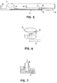
- a first precaution is to design the sample application site to overflow when more than the maximum volume of sample has been applied. This is easily accomplished by providing a cut-out slot 75 in the upper region of the application site lip 63, as shown in Figure 6 (in which dashed lines represent edges visible through the translucent plastic application region). This cut-out slot, which can be of any shape, also prevents formation of a sessile drop (i.e., drop 71 in Figure 5). This feature limits the maximum extent of the excess-sample volume to a range that can be dealt with by the other control elements. Of course, other techniques can also be used to avoid accumulation of excess sample at the application site.
- the capacity of the track connecting the sample application volume and the stacks can be selected to be just equal to, or preferably just slightly more than (by about 5 to 25%, preferably about 15%), the minimum volume required to fill the assay stack or stacks. In this way, much of the volume of sample is contained within the cartridge below the level of the top of the stack, so that the gravity pressure is minimized.
- samples ranging in volume from the minimum sample size to the volume of the stacks plus the volume of the sample-transport capillaries not only is the gravity force removed, but the capillary force becomes negative as the sample is drawn into the track.
- the stacks have very high capillary forces that can overcome the negative capillary force and gravity; the device therefore works properly even when remaining sample is drawn into the track, leaving the application site empty.
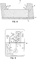
- a “ledge” can also be added to the stack cavity ( Figure 8) to minimize the volume of fluid that can accumulate on top of the stack.
- the edge of the ledge acts as a "stop-flow junction," which has been previously described for other operations in capillary cartridges.
- Two such ledges with appropriate edges 80 and 81 are visible in Figure 8. These edges are sharply defined and generally have interior angles of 90° or less.
- the ledge thickness in the vertical direction small, the pooling can be significantly reduced.
- the volume between the top of the stack and the top surface of the cartridge is by necessity quite large to reduce the risk of contaminating the monitor with sample.
- the ledge effectively reduces this volume that otherwise could fill completely with fluid.
- the ledge also helps to keep the potentially hazardous sample from contaminating the monitor. As will be seen from the discussion below, this ledge, combined with other control features, allows even the small amount of liquid on the stack surface to be eventually drawn back into the stack.
- Overflow/drain capillaries can also be added to the cartridge to actively prevent fluid accumulation above the stack.
- Two such capillaries are shown in Figure 9.
- the drains are located and sized so that sample preferentially flows into the capillaries that feed the stacks and into the stacks until all the stacks are full.
- the capillary force in the drain capillaries is greater than the forces that promote pooling. This dual requirement is easily achieved by choice of appropriate dimensions, as discussed below.
- the volume of the drain capillaries is chosen to accommodate the largest possible sample volume (i.e.,just enough to cause the application site to overflow). The drain capillaries will be better understood when considered with the other parts of cartridge 108.
- Capillary channel 21 itself leading from the application site to the assay sites has a volume slightly larger than the volume required to fill the assay sites 52, 54, and 55.
- the depths and widths of the capillary channels are designed to allow the entire sample applied in channel 21 to be drawn into the smaller capillary channels and assay sites beyond branch point 31.
- channel 21 can be 0.0381 cm (0.015") deep by 0.127 cm to 0.508 cm (.05 to 0.2") wide, whereas beyond branch point 31, the channels can be 0.038 cm (0.015") deep by 0.051 (0.02") wide.
- the overflow track 26/27 If excess sample is applied to the application site 11, some of it will flow into the overflow track 26/27.
- the capacity of this track is such that any amount of sample applied in one application to application site 11 could be accommodated in the large overflow channel 26/27.
- capillary forces will eventually draw sample back into the main channel, as the capillary pressure of the overflow is less strong than that of either the branching tracks leading to the assay sites or the stacks.
- the channel beyond 32 can increase from 0.038 cm (0.015") to 0.046 cm (0.018”) in depth, effectively reducing the capillary pressure.
- an overflow channel 29 branches off the main channel 28 at branch point 33.
- the capillary pressure of the overflow 29 is designed to be weaker than the capillary pressure of channel 28 and mixing chamber 35. In this way, when a minimum amount of sample is applied to 12, any sample diverted to the overflow 29 will eventually be pulled back into the main channel by higher capillary pressures. However, if excess sample has been applied to 12, the channel 29 has the capacity to contain the maximum possible volume applied in one application, avoiding the possible oversaturation of assay site 51 by retention of excess sample at the application site and the resulting gravitational pressure.
- the systems described above for control of sample volume can be readily summarized and understood by reference to the liquid-holding capacity of various parts of the cartridge.
- the cartridge is designed for application of a single drop of sample by a one-time operation that is as instantaneous as physically possible, such as by touching a drop of blood pendent from a finger (obtained by a capillary finger stick) to the application port.
- This application port typically a cavity located in an exterior surface of the housing that forms the cartridge, will have an inherent liquid-holding capacity resulting from the size of the cavity.
- the cavity is typically present in the portion of the housing that extends above its surrounding area so that excess sample applied to the cavity will merely flow off the sides of this raised portion onto the surface of the cartridge, where it can be retained by a surrounding lip, as shown in the Figures described above.
- the capacity of the application site therefore refers to the amount of sample that will enter the application site when added as a single bolus, as described above. This will typically be almost equal to the physical volume of the application port itself since flow into capillary 21 will be slow relative to the sample application rate.
- a second capacity that must be controlled is the capacity of the sample-transporting capillary passageway or passageways that are present in the housing connecting the sample application site to the reflectance reading site and its porous matrix.
- the capacity of this capillary passageway (here the singular is used to refer to all such passageways) is simply the volume of the passageway.
- overflow capillaries When overflow capillaries are present, their capacities are included in the capacity of the sample-transport system for comparison to the volume of the application site, but they are not considered when comparing to the matrix capacity, since, as discussed above, the directly transporting capillaries fill in preference to the overflow capillaries. More detail on appropriate capillaries to include in capacity comparisons to is given below.
- porous matrix itself in which a reflectance reading will be made will have an inherent internal capacity in its pores.
- capillary transport control typically involves controlling the radius of curvature for the leading and trailing sample meniscuses and the height of the sample at its two ends relative to each other.
- Meniscus curvature is readily accomplished by providing identical capillary cross-sectional dimensions at the locations where the leading and trailing edge of the sample will be found and by providing that the characteristics of the walls are the same at both locations.
- sample flow will cease if the trailing edge of the sample exerts a retarding force identical to the advancing capillary force at the leading edge of the sample regardless of the intervening structure of the capillary passageway.
- Another volume relationship that is maintained in a different (or the same) preferred embodiment is the relationship of the application-site capacity to the sum of the sample-transport capacity (both direct and overflow) and the porous-matrix capacity.
- the application-site capacity needs to be less than the sum, so that when excess sample is applied to the application site, it will flow away as previously described and therefore not remain in the physically higher application site to provide gravitational pressure on the sample in the matrix.
- the optical window design includes features to limit the rising of sample in the optical windows towards the optics, which can occur when the carrier membrane is full of plasma and there is excess sample still draining from the application site into the overflow areas (as might occur if a user accidentally applied sample again after the assay begins).
- the horizontal portions in the window break the upward force that normally pulls fluid up in a capillary. In this way, if excess fluid pools on the edges of the carrier membrane during flow of sample through the cartridge, this pooling is limited to a small volume, which is later quickly drained when all of the excess sample has been drained from the application site.
- a number of other fluid control capillaries can be used to advantage with any of the embodiments of the present invention.
- the embodiments of the Figures shown previously have a capillary in the interior of the housing that enters the space holding the assay stack at the edge of the assay stack.
- sample will enter the assay stack at one edge and spread through the assay stack horizontally as well as toward its upper surface where reflectance will be measured.
- Such side entry can result in uneven color formation on some reaction stacks, and more uniform entry of sample into the reaction stack is preferred.
- This can be accomplished in a number of ways.
- a horizontal, 4-walled capillary track can lead beneath the assay stack to the center of the stack and be connected thereto by a small vertical capillary.
- Sample then enters the center of the assay stack and spreads uniformly over the whole assay stack.
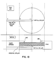
- the housing is generally prepared from two or more, preferably two, plastic pieces with the interior spaces being formed when the pieces are joined together. Because of the geometry required of the embodiment shown in Figure 10, at least three pieces are required.
- a cartridge formed from only two plastic cartridge parts can be prepared that provides satisfactory and substantially uniformed distribution of fluid into the assay stack.
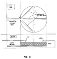
- FIG 11 Such an embodiment is shown in Figure 11, in which a 4-walled capillary track enters the space in which the assay stack will be located on the side much as before.
- the 4-walled capillary track is located just below the surface of the space that will contain the stack, and 3-walled capillary tracks (i.e., capillary spaces that are essentially grooves in the bottom surface of the area that will hold the assay stack) continue into the area beneath the assay stack.
- the bottom surface of the assay stack form the top surface (fourth wall) of these capillary tracks.
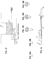
- FIG. 12 An alternative geometry that guides fluid to the center of the capillary stack as shown in in Figures 12 and 13.
- a typical sample-transport capillary 21 approaches the space beneath assay stack 53 and opening 65.
- Capillary 21 enters a wedge-like open space 41 beneath assay stack 53.
- At the bottom of space 41 is a small groove 42 which acts as a three-walled capillary channel in space 41.
- Groove 42 begins in the bottom of capillary channel 21 before channel 21 enters space 42.
- Panels A-E of Figure 13 which are cross-sectional views taken along lines A-A through E-E of Figure 12, shows the development of capillary groove 42 as views move from panel A to panel E. Additionally, the rising nature of the floor space 21 is illustrated in panels C-E.
- Capillary groove 42 acts to draw a sample entering space 41 upward along the bottom-sloping surface of space 41 so that sample contacts assay stack 53 at its center, thereby providing the desired uniformity of application.
- the capillary groove provides a strong force to draw sample toward the center of the matrix because of its small width.
- the space has a typical width of 0.051 cm (0.020") and the groove is typically 0.013 (0.005").
- FIG. 14 A further embodiment of the invention is shown in Figure 14.
- the previously described cartridges have all shown assay stacks on the same surface as the application site. While this is generally true, it is also possible to provide an assay stack on the opposite side of the cartridge from the application site.
- Such an embodiment is shown in cartridge 109 of Figure 14.
- application site 11 is located on a top surface of the cartridge, while capillary passageway 21 leads to assay stack 53 that is open to a reflectance reading through cavity 65 on the bottom surface of cartridge 109.
- the optical systems present in the monitor used to measure reflectance readings can be separated from each other more readily so that more optical readings can be taken in the same limited amount of space.
- the assay stacks used in a cartridge of the invention can vary widely depending on the specific assay being carried out.
- a simple, porous, reflective matrix can be used when previous chambers in the capillary passageway leading to the assay stack carry out all operations necessary for determination of a result other than the reflectance reading itself.
- the assay stack will comprise a reflective matrix along with other elements designed to handle fluids.
- a typical assay stack can comprise as the first element in order of contact by a sample supplied through the capillary passageway, a porous, fluid-handling and transfer element that contains one or more reagents or that otherwise acts upon the sample, for example by filtering red blood cells from plasma.
- Sample then passes from this initial porous element to a matrix from which the refleetance reading will be made.
- Reagents required for a particular analysis can be located anywhere in the capillary track leading from the application site to the reflective matrix, up to and including the matrix itself.
- assay stacks are set out in the examples that follow.
- the present invention is directed to the fluid handling system that directs sample to the very small assay stacks that are used in the present invention.
- any porous system designed to contain reagents and/or to be used to provide a reflectance reading can be used as an assay stack of the present invention.
- Numerous porous elements that provide for fluid handling in other manners are described in the patent and scientific literature. Small portions of such materials (such as could be prepared using a circular punch) can be cut out of numerous commercial preparations and inserted into a cartridge of the invention in order to utilize the fluid-handling characteristics of the cartridge.
- the present invention is not limited to any particular reaction stack or to any particular chemistry.
- An assay cartridge was prepared from ABS Plastic substantially in the form as described in Figures 2 and 3.
- the cartridge had a width of 4.45 cm (1.750") and a length of 15.88 cm (2.500").
- Application site 11 had a capacity of 45 l.
- Capillary 21 had a volume of 6.6 l with track dimensions of 0.102 cm (0.040") by 0.025 cm (0.010") in cross-sectional area.
- Branch capillaries 22, 23, 25, and 26 each had a volume of 0.3 ml and cross-sectional areas of 0.025 cm (0.010) by 0.025 cm (0.010").
- Intermediate capillary 24 had a volume of 0.9 l and a cross-sectional area of 0.051 cm (0.020) by 0.025 cm (0.010").
- the total matrix capacity was about 32-36 l.
- chemistry was optimized using a capillary track with a single application site, capillary track, and assay stack.
- Assay stacks have been optimized for a number of chemistries including hemoglobin assays.
- the assay stack for hemoglobin comprises 4 layers, numbered 1-4 in the order of blood contact.
- Layer 1 is a lysis disk made of ultra-high molecular weight polyethylene 0.0787 cm (0.031 inch) thick and having 54% porosity with an average pore size of 25.5 micron. The material is commercially available from Porex Technologies.
- Layer 2 is a spreading layer made of nylon mesh 3-2F/186 having a thickness of 22.86 cm (9 mil) (Tetko).
- Layer 3 is designed to trap fragments of red blood cells produced by lysis in the lysing disk. This is a polyether sulfone assymeteric membrane available from Sartorius.
- the fourth layer which is the reflectance reading matrix, is prepared from HT Tuffryn HT200 (TM) , a polysulfone material prepared by Gelman Sciences.
- TM HT Tuffryn HT200
- the lysing disk contains the only reagents in this system, namely a detergent that lyses the red blood cells (sodium deoxycholate and Theist) along with standard reagents for the measurement of hemoglobin. These reagents and their quantities are shown in Example 3.
- Theist and sodium deoxycholate which are surfactants, can be incorporated into a porous Porex filter of a multilayered assay stack to rupture the membrane of red blood cells in the sample to release hemoglobin. Hemoglobin is then oxidized to methemoglobin (FeIII) and together with azide form stable axidemethemoglobin. Hemoglobin concentration is directly proportional to color intensity. These reactions are shown below. Table I shows the reagent concentrations and components used to prepare a hemoglobin assay stack for use in a cartridge of the invention.
- Hemoglobin Test Composition, Reagent, Reagent Concentration Per Test, Vendor Reagents Quantity/Test (mg) Vendor Theist 1.836 Boehringer Mannheim Sodium Deoxycholate 0.366 Sigma Chemical Co. Sodium Nitrite 0.1829 Sigma Chemical Co. Sodium Azide 0.0306 Kodak Chemical Co. Glucose 0.3057 Sigma Chemical Co. UHMW Polyethylene / Porex Technologies Nylon Mesh / Tetko Co. HT200TM Polysulfone / Gelman Sciences
- the indicated reagents were dissolved in degassed D.I. water and stirred overnight at ambient temperature. Porex sheet stock was lowered into degassed Bulk Reagent solution so that the Porex carrier was impregnated completely and uniformly. Excess reagent was blotted from the supporting mesh before transfer to a drying tunnel. Preliminary drying was achieved in a drying tunnel of controlled air flow at 40°C for 4 hours. The reagent carriers were then subjected to a high vacuum for 12 hours. The resulting hemoglobin reagent carrier was stored in a dark drying containment at 4°C.
- the reagent carrier disk was used as layer 1 to prepare a reagent stack for hemoglobin by layering with the previously described stack layers 2-4 (see Example 1).
- the resulting reagent stack was inserted into a cartridge prepared as described above.
- Dose/response and clinical evaluations were carried out on the assay of the invention (Biotrack (TM) assay) and compared to the commercially available Hemocue (TM) ⁇ assay for hemoglobin using samples of whole blood. Results, which are shown in Tables 2 and 3, demonstrate that the cartridge of the invention is capable of producing useful clinical information while providing the advantages of the invention previously described.
- Hemoglobin Test Dose/Response Analyte (g/dL) K/S 5 0.3 10 0.7 15 1.1 20 1.4 25 1.7 Clinical Correlation for Hemoglobin Test Compared With Reference Method Sample Hb (g/dL) HemocueTM BiotrackTM 1 2.8 3.2 2 5.0 5.3 3 7.2 7.2 4 10.1 10.2 5 13.9 12.2 6 13.9 14.8 7 16.4 17.2 8 18.6 17.2 9 18.4 18.9 10 19.6 19.0
- Cartridges contained stacks comprised of antibody impregnated-polypropylene filters, Gelman TR-3000 (TM) membrane and two layers of ST-69 (Schleicher and Schuell). No assay chemistry was present in the stacks. Blood (45% hematocritTM), the corresponding plasma, and serum samples with known levels of hemolysis were applied to the cartridges in the usual way and K/S values recorded after 3 min. at 585 nm. To evaluate the effects red cells that were not removed by the filter blood containing known, samples with low hematocrits were applied directly to the optical surface of the stack.
- Example 4 Multi-analyte assay system: glucose, cholesterol, and hemoglobin determinations
- the layout of capillary tracks and stacks in multi-analyte assay cartridges is essentially equivalent to the cartridge shown in Figs. 2 and 3. All four stack cavities were filled with stacks which were of up to three different types.
- a plan view of the prototype cartridge is shown in Fig. 2.
- a sectional view of the assay stack is given in Fig. 3.
- the filter in the glucose and cholesterol stacks is a non-woven polypropylene felt (Ergon (TM) 193.26 g/m 2 (5.7 oz/sq. yrd.)) impregnated with antibody to red cells (Orgenon-Teknika (TM) , 1 mg/mL) then dried.
- the filter stacks also contain a membrane and a mesh to control fluid movement.
- Cartridges were assembled after punching discs of each element that are inserted into the upper part of the cartridge. The lower part of the cartridge is then welded to the upper to capture the stacks in the stack cavities and seal the capillary channels. Cartridges were individually pouched in aluminum/plastic foil with a desiccant pack.
- compositions of the assay chemistry are given below in terms of quantity per test:
- Aqueous compositions of the above formulated with buffers, stabilizing reagents and detergents were impregnated into the appropriate stack material and dried.
- red cells are removed by passable through a filter prior to moving into a "carrier" membrane which contains assay chemistry. Since some of the chemistries (glucose and cholesterol) require oxygen, the cartridge provides access to the atmosphere at the top surface of the assay stack.
- Calibrators were blood samples supplemented with analyte or diluted analyte-free plasma as needed.
- Assay protocols After insertion of the cartridge into the monitor, blood samples (typically 35 uL) were added to the sample application site. Reactions were generally followed for three minutes and reflectance values recorded after three minutes or when there was no change in reflectance with time. Usually, reflectance was measured at a single wavelength (585 nm) for all assays. Analyte concentrations in clinical samples and control materials were determined using the Kodak DT-60 (TM) for glucose and cholesterol and the HemocueTM ⁇ for hemoglobin.
- TM Kodak DT-60
- Relative reflectance R was usually defined as the ratio of signal after completion of the reaction to that recorded prior to wetting of the stack.
- K/S (1-R ⁇ 2/2R) was used to calculate K/S where K is the absorption coefficient of the chromophore/membrane pair which is a function of the absorbance and concentration of the chromophore and S is the scattering coefficient of the membrane.
- K/S is directly proportional to the concentration of colored product.
- K/S values were converted to analyte concentrations with a calibration function (usually a four-term polynomial) derived from data from at least five calibration materials spanning the assay range.
- the cartridge serves to deliver blood to the assay stacks to filter red cells in the cholesterol and glucose stacks and to mix sample and reagents. Good reproducibility of flow time from sample application site to stack and time to saturate the assay stack was found. The time from sample application to completion of the wetting of the optical surface ranged from 45 to 90 seconds for blood of 20 to 60% hematocrit (TM) respectively.
- the efficiency of the red cell filter was evaluated in glucose assay stacks omitting assay reagent and measuring the color of the optical membrane at 585 nm corresponding to a major absorbance of hemoglobin. Any leaked red cells or hemolysis would be detected in this way. Less than 1% leakage or hemolysis would be detected in this way. Less than 1% leakage or hemolysis was found.
- the filter works by agglutination of the red cells and depth filtration of the agglutinated cells in the fibrous mesh of the filter. The filter is effective for blood up to 60% hematocrit.
- the color yield corresponding to the assay quantitation range was determined both theoretically and by direct experiment. Yields were approximately 80% for the glucose and cholesterol assays and 100% for hemoglobin. For candidate membranes, S values were measured. By inspection of the results it was then possible to choose a membrane/chromophore pair that gives a range of K/S values closes to the optimum range of 0.2-2.0. This optimum range was calculated by applying error analysis. The error functions exhibit shallow minima in the K/S range 0.2 - 2.
- the assay chemistries selected use high concentrations of enzymes and excess enzyme substrates for rapid and complete conversion of analyte to the measured reaction product.
- a typical assay time course shows that about 20 seconds after sample application reflectance begins to decline. Prior to this decline the monitor determines stack reflectance and compares it with pre-established norms to verify that the cartridge is not defective. There is a rapid decline in reflectance as the optical membrane wets. This is due to the increase in refractive index of medium impregnating the membrane pores; air being replaced by plasma. This change causes reduction of the specific reflectance (S) of the membrane.
- S specific reflectance
- the reagents dissolve rapidly in the plasma and react with the analyte. Within typically two to three minutes, the reaction is complete as shown by the lack of change of reflectance.
- Bilirubin up to 600 mg/dL. Lipemia up to 12 g triglyceride/L and hemolysis up to 10 g/L have no significant impact on assay results.
- Hemolysis can occur due to inappropriate handling of the specimen.
- a simple algorithm constructed from the known spectral properties of the reaction product and of hemoglobin permits the calculation of both chromogen and hemoglobin concentrations from data collected at 585 nm (where the reaction product and hemoglobin both absorb strongly and 637 nm (where the reaction product absorbs and hemoglobin has little absorption). Hemoglobin concentrations less than those at which there is interference in the glucose and cholesterol assays are easily measured. Hemolyzed samples that would give incorrect assay results can be identified in this way.
Claims (33)
- Analysenkassette (101,102,103,104,105,106,107,108,109), umfassend:(a) ein flüssigkeitsundurchlässiges Gehäuse,(b) eine Probenaufbringstelle (11), die einen Hohlraum (71) umfaßt, der sich in einer Außenfläche des Gehäuses befindet und eine Aufbringstellen-Flüssigkeits-Haltekapazität aufweist,(c) eine Reflexions-Ablesestelle (51,52,53,54,55), die eine Kammer im Gehäuse umfaßt,(d) Mittel (61,62) zum Belüften der Kammer zur Atmosphäre,(e) einen Probentransport-Kapillarkanal (21) im Gehäuse, der die Probenaufbringstelle (11) mit der Reflexions-Ablesestelle verbindet und eine Probentransport-Flüssigkeitshaltekapazität aufweist, sowie(f) eine poröse Matrix, die sich in der Reflexions-Ablesestelle befindet und eine poröse Matrix-Flüssigkeitshaltekapazität aufweist,
dadurch gekennzeichnet, daß(g) die Probentransportkapazität gleich groß wie oder größer als die Kapazität der porösen Matrix ist,(h) die Aufbringstellenkapazität geringer als die Summe der Probentransportkapazität und der Kapazität der porösen Matrix ist, und(i) der Kapillarkanal so beschaffen ist, daß Kapillarkräfte am vorderen und am hinteren Ende einer Probe in diesem Kanal ausgeglichen sind, wenn eine Probe mit einem Volumen, das gleich jenem der Kapazität der porösen Matrix oder geringer als dieses ist, von der Probenaufbringstelle (11) her in den Kapillarkanal (21) eintritt. - Analysenkassette (101,102,103,104,105,106,107,108,109) nach Anspruch 1, worin der Probentransport-Kapillarkanal (21) Wandmittel umfaßt, um die Probe an den Positionen des vorderen und des hinteren Meniskus den ausgeglichenen Kräften auszusetzen, wenn eine Probe mit einem Volumen, das gleich dem der Kapazität der porösen Matrix oder geringer als dieses ist, von der Aufbringstelle (11) her in den Kapillarkanal (21) eintritt, wobei die Positionen des vorderen und des hinteren Meniskus für das dem der Matrixkapazität gleichende Probenvolumen als vordere Position des gleichen Volumens bzw. als hintere Position des gleichen Volumens identifiziert werden.
- Analysenkassette (101,102,103,104,105,106,107,108,109) nach Anspruch 2, worin der Kapillarkanal (21) und die Aufbringstelle (11) an einer Aufbringstellen-Verbindung verbunden sind und der Kapillarkanal (21) Wandmittel umfaßt, um an der Verbindungsstelle einen Krümmungsradius für einen an der Verbindungsstelle befindlichen hinteren Probenmeniskus zu schaffen, der einem Krümmungsradius für einen vorderen Probenmeniskus gleicht, der sich an der vorderen Position des gleichen Volumens befindet.
- Analysenkassette (101,102,103,104) nach Anspruch 2, worin der Kapillarkanal (21) an den Positionen des gleichen Volumens gleiche Querschnittsabmessungen aufweist.
- Analysenkassette (105,106,107,108) nach Anspruch 2, worin der Kapillarkanal (21) an den Positionen des gleichen Volumens unterschiedliche Querschnittsabmessungen aufweist, aber Wände der Kapillare mit unterschiedlichen Oberflächenenergien oder Gravitationspotentialen an den Positionen des gleichen Volumens die gleichen Kräfte ausüben.
- Analysenkassette (105) nach Anspruch 1, worin die Kassette Lenkmittel (63) umfaßt, um zu bewirken, daß eine Probe, die nahe der Aufbringstelle (11) aufgebracht wird, in die Aufbringstelle fließt.
- Analysenkassette (105) nach Anspruch 6, worin das Lenkmittel (63) eine Oberfläche umfaßt, die die Aufbringstelle im wesentlichen umgibt und zur Aufbringstelle (11) hin abfällt.
- Analysenkassette (105) nach Anspruch 6, worin das Lenkmittel (63) weiters Mittel (64) umfaßt, um über die Aufbringstellenkapazität hinausgehende Probe von der Aufbringstelle auszuschließen.
- Analysenkassette (105) nach Anspruch 8, worin das Lenkmittel (63) eine Oberfläche umfaßt, die die Aufbringstelle im wesentlichen umgibt und zur Aufbringstelle (11) hin abfällt, und das Mittel zum Ausschließen von Probe einen Schlitz in einem oberen Bereich der Oberfläche umfaßt.
- Analysenkassette (108) nach Anspruch 2, worin die Kassette weiters einen Überlaufkapillarkanal (26/27,29) umfaßt, der an einer Überlaufverbindung (32,33) mit dem Probentransport-Kapillarkanal (21,28) verbunden ist.
- Analysenkassette (108) nach Anspruch 10, worin die Überlaufverbindung (32) im Probentransport-Kapillarkanal (21) nach der vorderen Position des gleichen Volumens angeordnet ist.
- Analysenkassette (108) nach Anspruch 11, worin der Überlaufkapillarkanal (26/27) Wandmittel umfaßt, uni einen Meniskus zu bilden, der eine Kapillarkraft ausübt, die geringer als jene ist, die im Probentransport-Kapillarkanal (21) oder der porösen Matrix herrscht, wenn eine Probe im Überlaufkapillarkanal (26/27) und im Probentransport-Kapillarkanal (21) oder der porösen Matrix vorhanden ist.
- Analysenkassette nach Anspruch 10, worin die Überlaufverbindung (33) im Probentransport-Kapillarkanal vor der vorderen Position des gleichen Volumens angeordnet ist.
- Analysenkassette nach Anspruch 13, worin der Überlaufkapillarkanal (29) Wandmittel umfaßt, um einen Meniskus auszubilden, der eine Kapillarkraft ausübt, die geringer als jene ist, die im Probentransport-Kapillarkanal (28) herrscht, wenn eine Probe im Überlaufkapillarkanal (29) und im Probentransport-Kapillarkanal (28) vorhanden ist.
- Analysenkassette nach Anspruch 1, worin (1) die Kassette (101,102,103,104,105, 106,107,108) mehrere Reflexions-Ablesestellen (51,52,53,54,55) umfaßt, die mehrere Reflexions-Ablesematrizen enthalten, wobei die mehreren Matrizen gemeinsam die Kapazität der porösen Matrix aufweisen, und (2) der Probentransport-Kapillarkanal (21) (a) Verzweigungskapillaren (22,23,24,25,26) umfaßt, die von einer oder mehreren Verzweigungstellen (31,32) im Probentransport-Kapillarkanal (21) weg zu jeder der Stellen führen, sowie (b) eine anfängliche Hauptkapillare, welche die Probenaufbringstelle (11) mit einer ersten Verzweigungsstelle (31) der Verzweigungsstellen (31,32) im Probentransport-Kapillarkanal (21) verbindet.
- Analysenkassette (101,102,103,104,105,106,107,108) nach Anspruch 15, worin die Hauptkapillare eine Hauptflüssigkeitshaltekapazität aufweist, die größer als die Kapazität der porösen Matrix ist.
- Analysenkassette (101,102,103,104,105,106,107,108) nach Anspruch 16, worin die Verzweigungskapillaren (22,23,24,25,26) jeweils Wandmittel aufweisen, um eine bewegende Kapillarkraft auszuüben, die größer als die verzögernde Kapillarkraft in der Hauptkapillare (21) ist, wenn in der Probentransportkapillare (21) eine Probe vorhanden ist, und die Probe einen vorderen Meniskus in einer der Verzweigungskapillaren (22,23,24,25,26) und einen hinteren Meniskus in der Hauptkapillare (21) aufweist.
- Analysenkassette (101,102,103,104,105,106,107,108) nach Anspruch 17, worin die Hauptkapillare (21) Wandmittel umfaßt, um die Probe an den Positionen des vorderen und des hinteren Meniskus gleich großen bewegenden und verzögernden Kräften auszusetzen, wenn eine Probe mit einem Volumen, das gleich der Kapazität der porösen Matrix ist, von der Aufbringstelle (11) weg in die Hauptkapillare (21) eintritt, wodurch verhindert wird, daß die Probe in die Verzweigungskapillaren (22,23,24,25,26) fließt, wobei die Positionen des vorderen und des hinteren Meniskus für das der Matrixkapazität gleichende Probenvolumen als vordere Position des gleichen Volumens bzw. hintere Position des gleichen Volumens identifiziert werden.
- Analysenkassette (105,106,107,108) nach Anspruch 1, worin das Mittel zum Belüften eine Öffnung (61,62) in einer Deckfläche des Gehäuses in der Kammer umfaßt, wodurch eine Oberfläche der Reflexionsmatrix durch die Öffnung (61,62) hindurch äußerer Einstrahlung und Reflexion ausgesetzt ist.
- Analysenkassette (105,106,107,108) nach Anspruch 19, worin die Öffnung (61,62) eine Stop-Flow-Verbindung unterhalb der Deckfläche umfaßt.
- Analysenkassette (105,106,107,108) nach Anspruch 20, worin die Öffnung (61,62) kreisförmig ist und die Stop-Flow-Verbindung eine Leiste mit einer Kante mit einem Innenwinkel von 90° oder weniger umfaßt, die in die Öffnung hineinragt.
- Diagnosesystem, umfassend:(a) einen Monitor, umfassend:und(i) Mittel zum Detektieren Mehrfachreflexionsablesungen in einer Anordnung einzelner Positionen,(ii) Mittel zum Registrieren einer Analysenkassette an einer feststehenden Position und Ausrichtung relativ zur Anordnung in einem Innenraum des Monitors, und(iii) Mittel zum Bestimmen und Anzeigen von Analysenergebnissen durch Reflexionsablesungen, die an einzelnen Positionen in der Anordnung erhalten werden;(b) eine erste Analysenkassette (101,102,103,104,105,106,107,108) nach einem der vorangegangenen Ansprüche, worin sich die Probenaufbringstelle (11) im flüssigkeitsundurchlässigen Gehäuse an einer Position befindet, die außerhalb des Monitors liegt, wenn die Kassette durch Paßmittel im Monitor eingepaßt ist, und die eine oder mehrere Reflexionsablesestelle(n) (51,52) umfaßt, die im Gehäuse angeordnet ist/sind, um mit einer oder mehreren der Positionen in der Anordnung übereinzustimmen, wenn die Kassette im Monitor eingepaßt ist.
- System nach Anspruch 22, worin mehrere Reflexions-Ablesestellen (51,52) in der Kassette vorhanden sind.
- System nach Anspruch 23, worin das System weiters eine zweite Analysenkassette umfaßt, die fähig ist, zumindest einen Analyten unabhängig von den von der ersten Kassette gemessenen Analyten zu messen.
- System nach Anspruch 24, worin die zweite Analysenkassette zumindest eine Reflexions-Ablesestelle (53,54,55) an einer Position in der Anordnung umfaßt, die sich von den Reflexions-Ablesestellen (51,52), die von der ersten Analysenkassette verwendet werden, unterscheidet.
- System nach Anspruch 22, worin der Monitor weiters Mittel umfaßt, um die Analysenkassette (101,102,103,104,105,106,107,108,109) zu detektieren und zu identifizieren, wenn sie in den Monitor eingeschoben ist, und die Kassette weiters Informationen umfaßt, die auf der Kassette kodiert sind, wodurch das Mittel zum Detektieren und Identifizieren der Analysenkassette die Kassette als zu einen, vorbestimmten Kassettentyp gehörig identifiziert, der vom Monitor erkannt wird, wenn die Kassette in den Monitor eingeschoben ist.
- System nach Anspruch 26, worin die zweite Analysenkassette zumindest einen Kapillarkanal umfaßt, der sich von den Kapillarkanälen unterscheidet, die von der ersten Analysenkassette verwendet werden.
- System nach Anspruch 22, worin das Gehäuse einen Kapillarbaum umfaßt, der eine einzelne Aufbringstelle mit einer Vielzahl von Assaystapeln verbindet, worin der Kapillarbaum einen Anfangskapillarkanal (21) mit einer ersten Querschnittsfläche und einer Vielzahl von Verzweigungskapillarkanälen (22,23,24,25) umfaßt, der den Anfangskapillarkanal (21) mit den Assaystapeln (51,52,53,54) entweder direkt oder über weitere Verzweigungskapillarkanäle verbindet, worin jede der Verzweigungskapillaren in einem Kanal, der die Hauptkapillare mit einem der Assaystapel verbindet, enger als die Hauptkapillare und jegliche vorhergehende Verzweigungskapillare in der Verbindung ist.
- System nach Anspruch 22, worin die Reflexions-Ablesestellen (51,52,53,54,55) in einer Anordnung vorliegen, die auf einer ebenen Oberfläche des Gehäuses zugänglich ist.
- Sammlung von Analysenkassetten zum Detektieren mehrerer Analyten, umfassend eine erste und eine zweite Analysenkassette nach einem der Ansprüche 1 bis 21, wobei die erste Analysenkassette umfaßt:ein Mittel, um die Kassette als zu einen, vorbestimmten ersten Kassettentyp zugehörig zu identifizieren, undeinen Assaystapel (51), der sich in der Reflexions-Ablesestelle befindet; wobei die zweite Analysenkassette zum Bestimmen zumindest eines Analyten unabhängig von den von der ersten Kassette bestimmten Analyten umfaßt:Mittel, um die Kassette als zu einem vorbestimmten zweiten Kassettentyp gehörig zu identifizieren, undeinen Assaystapel (52), der sich der Reflexions-Ablesestelle befindet; und worin die erste und die zweite Analysenkassette so ausgebildet sind, daß sie in eine einzelne Ableseposition eines Monitors eingesetzt werden können, und die Reflexions-Ablesestellen in der ersten und der zweiten Kassette so angeordnet sind, daß sie von einer einzelnen Anordnung von im Monitor befindlichen Reflexionsablesevorrichtungen abgelesen werden können.
- Analysenkassette nach einem der Ansprüche 1 bis 21, weiters umfassend eine Öffnung (61,62) im Gehäuse in der Kammer, wodurch eine Oberfläche der Reflexionsmatrix durch die Öffnung hindurch potentieller äußerer Bestrahlung und Reflexion ausgesetzt ist, die eine Stop-Flow-Verbindung umfaßt.
- Analysenkassette (105,106,107,108) nach Anspruch 31, worin die Öffnung kreisförmig ist und die Stop-Flow-Verbindung eine Leiste mit einer Kante mit einem Innenwinkel von 90° oder weniger umfaßt.
- Analysenkassette (105,106,107,108) nach Anspruch 32, worin die Öffnung (61,62) kreisförmig ist und die Stop-Flow-Verbindung an einer Verbindungsstelle in der Öffnung vorliegt, wo die Öffnung von einem proximalen geringeren Durchmesser zu einem distalen größeren Durchmesser übergeht, wobei die proximale und die distale Position in der Öffnung auf die Oberfläche der Reflexionsmatrix bezogen sind.
Applications Claiming Priority (3)
| Application Number | Priority Date | Filing Date | Title |
|---|---|---|---|
| US867162 | 1986-05-27 | ||
| US07/867,162 US5223219A (en) | 1992-04-10 | 1992-04-10 | Analytical cartridge and system for detecting analytes in liquid samples |
| PCT/US1993/003361 WO1993020939A1 (en) | 1992-04-10 | 1993-04-07 | Analytical cartridge and system for detecting analytes |
Publications (3)
| Publication Number | Publication Date |
|---|---|
| EP0593714A1 EP0593714A1 (de) | 1994-04-27 |
| EP0593714A4 EP0593714A4 (de) | 1995-06-21 |
| EP0593714B1 true EP0593714B1 (de) | 1998-08-19 |
Family
ID=25349242
Family Applications (1)
| Application Number | Title | Priority Date | Filing Date |
|---|---|---|---|
| EP93909303A Expired - Lifetime EP0593714B1 (de) | 1992-04-10 | 1993-04-07 | Analysenkassette und system zum aufspüren von analyten |
Country Status (8)
| Country | Link |
|---|---|
| US (1) | US5223219A (de) |
| EP (1) | EP0593714B1 (de) |
| JP (1) | JP2944216B2 (de) |
| AU (1) | AU3976793A (de) |
| CA (1) | CA2109704C (de) |
| DE (1) | DE69320437T2 (de) |
| ES (1) | ES2123050T3 (de) |
| WO (1) | WO1993020939A1 (de) |
Families Citing this family (172)
| Publication number | Priority date | Publication date | Assignee | Title |
|---|---|---|---|---|
| US6953676B1 (en) * | 1992-05-01 | 2005-10-11 | Trustees Of The University Of Pennsylvania | Mesoscale polynucleotide amplification device and method |
| US5302348A (en) * | 1992-12-10 | 1994-04-12 | Itc Corporation | Blood coagulation time test apparatus and method |
| US5503985A (en) * | 1993-02-18 | 1996-04-02 | Cathey; Cheryl A. | Disposable device for diagnostic assays |
| US5798215A (en) * | 1993-02-18 | 1998-08-25 | Biocircuits Corporation | Device for use in analyte detection assays |
| GB9307319D0 (en) * | 1993-04-07 | 1993-06-02 | British Tech Group | Liquid transfer devices |
| US5837546A (en) * | 1993-08-24 | 1998-11-17 | Metrika, Inc. | Electronic assay device and method |
| AU7563294A (en) * | 1993-08-24 | 1995-03-21 | Metrika Laboratories, Inc. | Novel disposable electronic assay device |
| US5416026A (en) * | 1993-10-04 | 1995-05-16 | I-Stat Corporation | Method for detecting the change in an analyte due to hemolysis in a fluid sample |
| JPH09508200A (ja) * | 1993-12-28 | 1997-08-19 | アボツト,ラボラトリーズ | 表面下流を有する装置及び診断検定におけるその使用 |
| US5478751A (en) * | 1993-12-29 | 1995-12-26 | Abbott Laboratories | Self-venting immunodiagnositic devices and methods of performing assays |
| US5731212A (en) * | 1994-12-20 | 1998-03-24 | International Technidyne Corporation | Test apparatus and method for testing cuvette accommodated samples |
| US5695949A (en) * | 1995-04-07 | 1997-12-09 | Lxn Corp. | Combined assay for current glucose level and intermediate or long-term glycemic control |
| US5942443A (en) * | 1996-06-28 | 1999-08-24 | Caliper Technologies Corporation | High throughput screening assay systems in microscale fluidic devices |
| US6399023B1 (en) * | 1996-04-16 | 2002-06-04 | Caliper Technologies Corp. | Analytical system and method |
| US5968839A (en) * | 1996-05-13 | 1999-10-19 | Metrika, Inc. | Method and device producing a predetermined distribution of detectable change in assays |
| BR9710054A (pt) * | 1996-06-28 | 2000-01-11 | Caliper Techn Corp | Aparelhos para separar compostos de teste para um efeito sobre um sistema bioquìmico e para detectar ummefeito de um composto de teste sobre um sistema bioquìmico, processos de determinação de se uma amostra contém um composto capaz de afetar um sistema bioquìmico, de separação de uma pluralidade de compostos de teste para um efeito sobre um sistema bioquìmico e usos de um sistema microfluido e de um substrato de ensaio. |
| DK0921840T3 (da) | 1996-07-03 | 2003-09-22 | Altea Therapeutics Corp | Multipel mekanisk mikroperforering af hud eller slimhinde |
| US5945345A (en) * | 1996-08-27 | 1999-08-31 | Metrika, Inc. | Device for preventing assay interference using silver or lead to remove the interferant |
| US6527716B1 (en) | 1997-12-30 | 2003-03-04 | Altea Technologies, Inc. | Microporation of tissue for delivery of bioactive agents |
| US20050101032A1 (en) * | 1997-02-10 | 2005-05-12 | Metrika, Inc. | Assay device, composition, and method of optimizing assay sensitivity |
| US5885839A (en) * | 1997-04-15 | 1999-03-23 | Lxn Corporation | Methods of determining initiation and variable end points for measuring a chemical reaction |
| US6613512B1 (en) * | 1997-06-09 | 2003-09-02 | Caliper Technologies Corp. | Apparatus and method for correcting for variable velocity in microfluidic systems |
| US6082185A (en) * | 1997-07-25 | 2000-07-04 | Research International, Inc. | Disposable fluidic circuit cards |
| ES2309022T3 (es) * | 1997-12-24 | 2008-12-16 | Cepheid | Dispositivo y procedimiento para lisis. |
| US6394952B1 (en) | 1998-02-03 | 2002-05-28 | Adeza Biomedical Corporation | Point of care diagnostic systems |
| US6267722B1 (en) | 1998-02-03 | 2001-07-31 | Adeza Biomedical Corporation | Point of care diagnostic systems |
| US6004821A (en) * | 1998-03-07 | 1999-12-21 | Levine; Robert A. | Method and apparatus for performing chemical, qualitative, quantitative, and semi-quantitative analyses of a urine sample |
| US6929953B1 (en) * | 1998-03-07 | 2005-08-16 | Robert A. Levine | Apparatus for analyzing biologic fluids |
| US6723290B1 (en) * | 1998-03-07 | 2004-04-20 | Levine Robert A | Container for holding biologic fluid for analysis |
| WO1999046591A2 (en) | 1998-03-10 | 1999-09-16 | Strategic Diagnostics, Inc. | Integrated assay device and methods of production and use |
| IL138286A (en) * | 1998-03-11 | 2004-02-19 | Steag Micro Parts Gmbh | Sample support |
| AU3491299A (en) * | 1998-04-14 | 1999-11-01 | Lumenal Technologies, L.P. | Test cartridge with a single inlet port |
| USD432244S (en) * | 1998-04-20 | 2000-10-17 | Adeza Biomedical Corporation | Device for encasing an assay test strip |
| USD434153S (en) * | 1998-04-20 | 2000-11-21 | Adeza Biomedical Corporation | Point of care analyte detector system |
| US20060019404A1 (en) * | 1998-05-06 | 2006-01-26 | Blatt Joel M | Quantitative assay with extended dynamic range |
| WO2000022436A1 (en) * | 1998-10-13 | 2000-04-20 | Biomicro Systems, Inc. | Fluid circuit components based upon passive fluid dynamics |
| US6591852B1 (en) | 1998-10-13 | 2003-07-15 | Biomicro Systems, Inc. | Fluid circuit components based upon passive fluid dynamics |
| US6601613B2 (en) | 1998-10-13 | 2003-08-05 | Biomicro Systems, Inc. | Fluid circuit components based upon passive fluid dynamics |
| US6637463B1 (en) | 1998-10-13 | 2003-10-28 | Biomicro Systems, Inc. | Multi-channel microfluidic system design with balanced fluid flow distribution |
| US6240790B1 (en) * | 1998-11-09 | 2001-06-05 | Agilent Technologies, Inc. | Device for high throughout sample processing, analysis and collection, and methods of use thereof |
| US6431476B1 (en) | 1999-12-21 | 2002-08-13 | Cepheid | Apparatus and method for rapid ultrasonic disruption of cells or viruses |
| US6887693B2 (en) | 1998-12-24 | 2005-05-03 | Cepheid | Device and method for lysing cells, spores, or microorganisms |
| US7914994B2 (en) | 1998-12-24 | 2011-03-29 | Cepheid | Method for separating an analyte from a sample |
| US6416642B1 (en) * | 1999-01-21 | 2002-07-09 | Caliper Technologies Corp. | Method and apparatus for continuous liquid flow in microscale channels using pressure injection, wicking, and electrokinetic injection |
| US20020019059A1 (en) * | 1999-01-28 | 2002-02-14 | Calvin Y.H. Chow | Devices, systems and methods for time domain multiplexing of reagents |
| US6555389B1 (en) * | 1999-05-11 | 2003-04-29 | Aclara Biosciences, Inc. | Sample evaporative control |
| US9073053B2 (en) | 1999-05-28 | 2015-07-07 | Cepheid | Apparatus and method for cell disruption |
| US20040200909A1 (en) * | 1999-05-28 | 2004-10-14 | Cepheid | Apparatus and method for cell disruption |
| US6818185B1 (en) | 1999-05-28 | 2004-11-16 | Cepheid | Cartridge for conducting a chemical reaction |
| US8815521B2 (en) | 2000-05-30 | 2014-08-26 | Cepheid | Apparatus and method for cell disruption |
| DE60014676T2 (de) * | 1999-05-28 | 2005-11-17 | Cepheid, Sunnyvale | Vorrichtung und verfahren zur analyse flüssiger proben |
| US6811668B1 (en) | 1999-06-22 | 2004-11-02 | Caliper Life Sciences, Inc. | Apparatus for the operation of a microfluidic device |
| ATE372830T1 (de) † | 1999-07-07 | 2007-09-15 | 3M Innovative Properties Co | Mikrofluidischer artikel |
| US7223364B1 (en) * | 1999-07-07 | 2007-05-29 | 3M Innovative Properties Company | Detection article having fluid control film |
| JP4627395B2 (ja) * | 1999-08-11 | 2011-02-09 | 旭化成株式会社 | 分析用カートリッジ及び送液制御装置 |
| US20030078499A1 (en) * | 1999-08-12 | 2003-04-24 | Eppstein Jonathan A. | Microporation of tissue for delivery of bioactive agents |
| US6495104B1 (en) * | 1999-08-19 | 2002-12-17 | Caliper Technologies Corp. | Indicator components for microfluidic systems |
| US6696240B1 (en) | 1999-10-26 | 2004-02-24 | Micronix, Inc. | Capillary test strip to separate particulates |
| US6900059B1 (en) | 1999-11-26 | 2005-05-31 | Associates Of Cape Cod, Inc. | Reader for conducting assays |
| JP2001281233A (ja) * | 2000-03-28 | 2001-10-10 | Inst Of Physical & Chemical Res | 水性分配用マイクロチップおよびそれを用いた水性分配方法 |
| US6908593B1 (en) * | 2000-03-31 | 2005-06-21 | Lifescan, Inc. | Capillary flow control in a fluidic diagnostic device |
| WO2001089691A2 (en) * | 2000-05-24 | 2001-11-29 | Micronics, Inc. | Capillaries for fluid movement within microfluidic channels |
| SG100731A1 (en) * | 2000-08-30 | 2003-12-26 | Wardlaw Partners Lp | Container for holding biologic fluid for analysis |
| WO2002054052A1 (en) * | 2001-01-08 | 2002-07-11 | Leonard Fish | Diagnostic instruments and methods for detecting analytes |
| JP4244534B2 (ja) | 2001-06-12 | 2009-03-25 | 横河電機株式会社 | バイオチップ |
| US6740293B1 (en) * | 2001-07-17 | 2004-05-25 | Biotech Atlantic, Inc. | Housing for test strip device and test strip therefor |
| BR0212774B1 (pt) * | 2001-09-24 | 2011-11-29 | Circuito respiratório com uma ramificação e múltiplos lúmens. | |
| US6836332B2 (en) * | 2001-09-25 | 2004-12-28 | Tennessee Scientific, Inc. | Instrument and method for testing fluid characteristics |
| US6989891B2 (en) | 2001-11-08 | 2006-01-24 | Optiscan Biomedical Corporation | Device and method for in vitro determination of analyte concentrations within body fluids |
| US7004928B2 (en) | 2002-02-08 | 2006-02-28 | Rosedale Medical, Inc. | Autonomous, ambulatory analyte monitor or drug delivery device |
| US7183069B2 (en) * | 2002-03-07 | 2007-02-27 | Toyama University | Reagent, method and apparatus for measuring amylase activity |
| US7186696B2 (en) * | 2002-03-07 | 2007-03-06 | Toyama University | Reagent and method for measuring amylase |
| US9918665B2 (en) | 2002-03-11 | 2018-03-20 | Nitto Denko Corporation | Transdermal porator and patch system and method for using same |
| ES2701884T3 (es) * | 2002-03-11 | 2019-02-26 | Nitto Denko Corp | Sistema de parche de administración transdérmica de fármacos |
| US8116860B2 (en) * | 2002-03-11 | 2012-02-14 | Altea Therapeutics Corporation | Transdermal porator and patch system and method for using same |
| US7285425B2 (en) * | 2002-05-14 | 2007-10-23 | Siemens Medical Solutions Diagnostics | Assay test system for regulating temperature |
| US7197169B2 (en) * | 2003-01-02 | 2007-03-27 | Kuo-Jeng Wang | Method for detecting a response of each probe zone on a test strip |
| US6983177B2 (en) | 2003-01-06 | 2006-01-03 | Optiscan Biomedical Corporation | Layered spectroscopic sample element with microporous membrane |
| US20040131088A1 (en) * | 2003-01-08 | 2004-07-08 | Adtran, Inc. | Shared T1/E1 signaling bit processor |
| US7052652B2 (en) * | 2003-03-24 | 2006-05-30 | Rosedale Medical, Inc. | Analyte concentration detection devices and methods |
| US20050037384A1 (en) * | 2003-04-15 | 2005-02-17 | Braig James R. | Analyte detection system |
| US20050037508A1 (en) * | 2003-08-12 | 2005-02-17 | Juan Hernandez | Microfluidic titration apparatus |
| US8016811B2 (en) | 2003-10-24 | 2011-09-13 | Altea Therapeutics Corporation | Method for transdermal delivery of permeant substances |
| US20060088857A1 (en) * | 2003-12-01 | 2006-04-27 | Said Attiya | Method for isolation of independent, parallel chemical micro-reactions using a porous filter |
| US20060019264A1 (en) * | 2003-12-01 | 2006-01-26 | Said Attiya | Method for isolation of independent, parallel chemical micro-reactions using a porous filter |
| US7150995B2 (en) * | 2004-01-16 | 2006-12-19 | Metrika, Inc. | Methods and systems for point of care bodily fluid analysis |
| US20070178521A1 (en) * | 2004-03-16 | 2007-08-02 | Yoshiki Sakaino | Assay chip |
| JP2007532878A (ja) * | 2004-04-06 | 2007-11-15 | バイオ/データ・コーポレイション | 使い捨て試験装置と検体量測定/混合方法 |
| US7887750B2 (en) * | 2004-05-05 | 2011-02-15 | Bayer Healthcare Llc | Analytical systems, devices, and cartridges therefor |
| US20050264815A1 (en) * | 2004-05-07 | 2005-12-01 | Mark Wechsler | Sample element with fringing-reduction capabilities |
| JP2008513791A (ja) * | 2004-09-20 | 2008-05-01 | バイエル・ヘルスケア・エルエルシー | 光学センサおよびその製造方法 |
| TW200642655A (en) * | 2005-02-01 | 2006-12-16 | Bayer Healthcare Llc | Sensor and package |
| US20060194325A1 (en) * | 2005-02-14 | 2006-08-31 | Gable Jennifer H | Fluid handling cassette with a fluid control interface |
| US8936755B2 (en) | 2005-03-02 | 2015-01-20 | Optiscan Biomedical Corporation | Bodily fluid composition analyzer with disposable cassette |
| US8251907B2 (en) * | 2005-02-14 | 2012-08-28 | Optiscan Biomedical Corporation | System and method for determining a treatment dose for a patient |
| CN101180540A (zh) * | 2005-03-29 | 2008-05-14 | 因弗因斯医药瑞士股份有限公司 | 混合器件 |
| US20090054741A1 (en) * | 2005-03-29 | 2009-02-26 | Inverness Medical Switzerland Gmbh | Device and method of monitoring a patient |
| US20060281187A1 (en) | 2005-06-13 | 2006-12-14 | Rosedale Medical, Inc. | Analyte detection devices and methods with hematocrit/volume correction and feedback control |
| US20090268548A1 (en) * | 2005-08-11 | 2009-10-29 | Eksigent Technologies, Llc | Microfluidic systems, devices and methods for reducing diffusion and compliance effects at a fluid mixing region |
| US7938573B2 (en) * | 2005-09-02 | 2011-05-10 | Genefluidics, Inc. | Cartridge having variable volume reservoirs |
| US8801631B2 (en) | 2005-09-30 | 2014-08-12 | Intuity Medical, Inc. | Devices and methods for facilitating fluid transport |
| JP4830432B2 (ja) * | 2005-09-30 | 2011-12-07 | 横河電機株式会社 | 化学反応用カートリッジおよびその使用方法 |
| EP3461406A1 (de) | 2005-09-30 | 2019-04-03 | Intuity Medical, Inc. | Kassette zur entnahme und analyse von körperflüssigkeiten mit mehreren stellen |
| JP4692200B2 (ja) * | 2005-10-06 | 2011-06-01 | 横河電機株式会社 | 化学処理用カートリッジおよびその使用方法 |
| US9561001B2 (en) | 2005-10-06 | 2017-02-07 | Optiscan Biomedical Corporation | Fluid handling cassette system for body fluid analyzer |
| JP4852399B2 (ja) * | 2006-11-22 | 2012-01-11 | 富士フイルム株式会社 | 二液合流装置 |
| CN101970111B (zh) | 2007-06-21 | 2013-09-11 | 简·探针公司 | 用于执行处理的仪器和容器 |
| JPWO2009110089A1 (ja) * | 2008-03-07 | 2011-07-14 | 株式会社ティー・ワイ・エー | 体液成分の分析器具 |
| JP5816080B2 (ja) | 2008-05-30 | 2015-11-17 | インテュイティ メディカル インコーポレイテッド | 体液採取装置及び採取部位インターフェイス |
| US10383556B2 (en) | 2008-06-06 | 2019-08-20 | Intuity Medical, Inc. | Medical diagnostic devices and methods |
| JP5642066B2 (ja) | 2008-06-06 | 2014-12-17 | インテュイティ メディカル インコーポレイテッド | 体液の試料内に含まれている検体の存在または濃度を決定する検定を行う方法および装置 |
| US8448499B2 (en) | 2008-12-23 | 2013-05-28 | C A Casyso Ag | Cartridge device for a measuring system for measuring viscoelastic characteristics of a sample liquid, a corresponding measuring system, and a corresponding method |
| WO2010115454A1 (en) * | 2009-04-06 | 2010-10-14 | Trinean Nv | Sample storage in microfluidics devices |
| WO2010131514A1 (ja) * | 2009-05-15 | 2010-11-18 | コニカミノルタオプト株式会社 | マイクロチップ |
| AU2010257118B2 (en) | 2009-06-04 | 2014-08-28 | Lockheed Martin Corporation | Multiple-sample microfluidic chip for DNA analysis |
| US9554742B2 (en) | 2009-07-20 | 2017-01-31 | Optiscan Biomedical Corporation | Fluid analysis system |
| US8731638B2 (en) | 2009-07-20 | 2014-05-20 | Optiscan Biomedical Corporation | Adjustable connector and dead space reduction |
| KR101044556B1 (ko) * | 2009-09-03 | 2011-06-28 | 주식회사 인포피아 | 카메라를 이용한 검체 정량 측정 기기, 방법 및 시스템 |
| CA2782047C (en) * | 2009-11-30 | 2019-10-29 | Intuity Medical, Inc. | Calibration material delivery devices and methods |
| CN106110923A (zh) * | 2009-12-18 | 2016-11-16 | 艾博特健康公司 | 生物流体样本分析卡盒 |
| US9199233B2 (en) | 2010-03-31 | 2015-12-01 | Abbott Point Of Care, Inc. | Biologic fluid analysis cartridge with deflecting top panel |
| EP2562539B1 (de) | 2010-03-31 | 2023-09-27 | Sekisui Medical Co., Ltd. | Verfahren zur analyse von hämoglobinen |
| US10330667B2 (en) | 2010-06-25 | 2019-06-25 | Intuity Medical, Inc. | Analyte monitoring methods and systems |
| CA2814720C (en) | 2010-10-15 | 2016-12-13 | Lockheed Martin Corporation | Micro fluidic optic design |
| WO2012092593A1 (en) | 2010-12-30 | 2012-07-05 | Abbott Point Of Care, Inc. | Biologic fluid analysis cartridge with sample handling portion and analysis chamber portion |
| WO2013006716A1 (en) | 2011-07-06 | 2013-01-10 | Optiscan Biomedical Corporation | Sample cell for fluid analysis system |
| EP3407064B1 (de) | 2011-08-03 | 2020-04-22 | Intuity Medical, Inc. | Vorrichtung zur entnahme von körperflüssigkeiten |
| JP5906604B2 (ja) * | 2011-08-11 | 2016-04-20 | 東洋紡株式会社 | 全血検体の成分測定方法 |
| CN105817276B (zh) | 2011-08-24 | 2018-02-06 | 艾博特健康公司 | 生物流体样品分析盒 |
| EP2751021A4 (de) | 2011-08-30 | 2015-09-30 | Univ Mcgill | Verfahren und system für vorprogrammierte und selbstangetriebene mikrofluidische schaltungen |
| US9322054B2 (en) | 2012-02-22 | 2016-04-26 | Lockheed Martin Corporation | Microfluidic cartridge |
| DK2825309T3 (en) | 2012-03-16 | 2018-07-30 | Stat Diagnostica & Innovation Sl | Sample cartridge with integrated transfer module |
| US9081001B2 (en) | 2012-05-15 | 2015-07-14 | Wellstat Diagnostics, Llc | Diagnostic systems and instruments |
| US9213043B2 (en) | 2012-05-15 | 2015-12-15 | Wellstat Diagnostics, Llc | Clinical diagnostic system including instrument and cartridge |
| US9625465B2 (en) | 2012-05-15 | 2017-04-18 | Defined Diagnostics, Llc | Clinical diagnostic systems |
| CA2912283A1 (en) | 2013-06-21 | 2014-12-21 | Intuity Medical, Inc. | Analyte monitoring system with audible feedback |
| EP3151965B1 (de) | 2014-06-04 | 2021-02-24 | Edan Instruments, Inc. | Vorrichtungen zur probennahme und -analyse |
| US10816559B2 (en) | 2014-09-29 | 2020-10-27 | Ca Casyso Ag | Blood testing system and method |
| US10539579B2 (en) | 2014-09-29 | 2020-01-21 | C A Casyso Gmbh | Blood testing system and method |
| US10175225B2 (en) | 2014-09-29 | 2019-01-08 | C A Casyso Ag | Blood testing system and method |
| US9897618B2 (en) | 2014-09-29 | 2018-02-20 | C A Casyso Gmbh | Blood testing system |
| US10288630B2 (en) | 2014-09-29 | 2019-05-14 | C A Casyso Gmbh | Blood testing system and method |
| USD777343S1 (en) | 2015-05-28 | 2017-01-24 | C A Casyso Ag | Body fluid cartridge device |
| US10295554B2 (en) | 2015-06-29 | 2019-05-21 | C A Casyso Gmbh | Blood testing system and method |
| WO2017027643A1 (en) | 2015-08-10 | 2017-02-16 | Essenlix Corp. | Bio/chemical assay devices and methods for simplified steps, small samples, accelerated speed, and ease-of-use |
| KR101982330B1 (ko) | 2015-09-14 | 2019-05-24 | 에센릭스 코프. | 증기 응축액 특히 입김 응축액을 수집 및 분석하기 위한 장치 및 시스템 그리고 이 장치 및 시스템을 사용하는 방법 |
| SG10202104563UA (en) | 2015-09-14 | 2021-06-29 | Essenlix Corp | Device and system for analyzing a sample, particularly blood, as well as methods of using the same |
| WO2017117553A1 (en) * | 2015-12-31 | 2017-07-06 | Mec Dynamics | Micro mechanical methods and systems for performing assays |
| KR101708473B1 (ko) * | 2016-01-15 | 2017-02-20 | 경상대학교산학협력단 | 역 y자 형태의 진단 스트립을 포함하는 잔류농약 검출용 키트 및 상기 키트를 이용한 잔류농약 검출 방법 |
| US11041860B2 (en) * | 2016-03-18 | 2021-06-22 | Analytical Diagnostic Solutions, Inc. | Point-of-care device for the colorimetric determination of hemoglobin and glucose-6-phosphate dehydrogenase in biological samples |
| US10473674B2 (en) | 2016-08-31 | 2019-11-12 | C A Casyso Gmbh | Controlled blood delivery to mixing chamber of a blood testing cartridge |
| GB201615320D0 (en) | 2016-09-09 | 2016-10-26 | Invitron Ltd | Point of care platform test |
| CN110312473B (zh) | 2016-12-21 | 2023-04-07 | 艾森利克斯公司 | 用于认证样本的装置和方法及其使用 |
| CA3052786A1 (en) | 2017-02-07 | 2018-08-16 | Essenlix Corporation | Compressed open flow assay and use |
| CA3053002A1 (en) | 2017-02-08 | 2018-08-16 | Essenlix Corp. | Bio/chemical material extraction and assay |
| CA3053132A1 (en) | 2017-02-09 | 2018-08-16 | Essenlix Corp. | Assay with amplification |
| EP3580565A4 (de) | 2017-02-09 | 2021-04-21 | Essenlix Corporation | Assay mit verschiedenen abstandshöhen |
| EP3662259A4 (de) | 2017-02-09 | 2021-08-25 | Essenlix Corporation | Kolorimetrische tests |
| US11523752B2 (en) | 2017-02-16 | 2022-12-13 | Essenlix Corporation | Assay for vapor condensates |
| US10843185B2 (en) | 2017-07-12 | 2020-11-24 | Ca Casyso Gmbh | Autoplatelet cartridge device |
| WO2019028123A1 (en) | 2017-08-01 | 2019-02-07 | Essenlix Corporation | COLLECTION, MAINTENANCE AND DETERMINATION OF SAMPLES |
| US11280706B2 (en) | 2017-08-01 | 2022-03-22 | Essenlix Corporation | Dilution calibration |
| US11725227B2 (en) | 2017-08-01 | 2023-08-15 | Essenlix Corporation | Devices and methods for examining drug effects on microorganisms |
| WO2019075415A1 (en) | 2017-10-13 | 2019-04-18 | Essenlix Corporation | DEVICES AND METHODS FOR AUTHENTICATING MEDICAL ANALYSIS AND USES THEREOF |
| US11237113B2 (en) | 2017-10-26 | 2022-02-01 | Essenlix Corporation | Rapid pH measurement |
| US11609224B2 (en) | 2017-10-26 | 2023-03-21 | Essenlix Corporation | Devices and methods for white blood cell analyses |
| US10807095B2 (en) | 2017-10-26 | 2020-10-20 | Essenlix Corporation | Making and tracking assay card |
| US11648551B2 (en) | 2017-12-12 | 2023-05-16 | Essenlix Corporation | Sample manipulation and assay with rapid temperature change |
| US11510608B2 (en) | 2017-12-14 | 2022-11-29 | Essenlix Corporation | Devices, systems, and methods for monitoring hair |
| WO2019140334A1 (en) | 2018-01-11 | 2019-07-18 | Essenlix Corporation | Homogeneous assay (ii) |
| US11885952B2 (en) | 2018-07-30 | 2024-01-30 | Essenlix Corporation | Optics, device, and system for assaying and imaging |
| EP3892983A1 (de) * | 2020-04-08 | 2021-10-13 | Labinlight Lda | Systeme, vorrichtungen, komponenten und verfahren zur analyse von körperflüssigkeitsproben |
Family Cites Families (17)
| Publication number | Priority date | Publication date | Assignee | Title |
|---|---|---|---|---|
| US3799742A (en) * | 1971-12-20 | 1974-03-26 | C Coleman | Miniaturized integrated analytical test container |
| US4233029A (en) * | 1978-10-25 | 1980-11-11 | Eastman Kodak Company | Liquid transport device and method |
| US4426451A (en) * | 1981-01-28 | 1984-01-17 | Eastman Kodak Company | Multi-zoned reaction vessel having pressure-actuatable control means between zones |
| US4618476A (en) * | 1984-02-10 | 1986-10-21 | Eastman Kodak Company | Capillary transport device having speed and meniscus control means |
| US4689202A (en) * | 1984-09-11 | 1987-08-25 | Miles Laboratories, Inc. | Reagent test strip reading instrument |
| US4627445A (en) * | 1985-04-08 | 1986-12-09 | Garid, Inc. | Glucose medical monitoring system |
| US4756884A (en) * | 1985-08-05 | 1988-07-12 | Biotrack, Inc. | Capillary flow device |
| US5004923A (en) * | 1985-08-05 | 1991-04-02 | Biotrack, Inc. | Capillary flow device |
| US4753776A (en) * | 1986-10-29 | 1988-06-28 | Biotrack, Inc. | Blood separation device comprising a filter and a capillary flow pathway exiting the filter |
| US4820647A (en) * | 1986-12-03 | 1989-04-11 | Biotrack, Inc. | Method for detecting a metal ion in an aqueous environment |
| US5077017A (en) * | 1987-11-05 | 1991-12-31 | Biotrack, Inc. | Integrated serial dilution and mixing cartridge |
| US4829011A (en) * | 1987-08-27 | 1989-05-09 | Biotrack, Inc. | Agglutination assay |
| US4868129A (en) * | 1987-08-27 | 1989-09-19 | Biotrack Inc. | Apparatus and method for dilution and mixing of liquid samples |
| US4946795A (en) * | 1987-08-27 | 1990-08-07 | Biotrack, Inc. | Apparatus and method for dilution and mixing of liquid samples |
| US5039617A (en) * | 1989-04-20 | 1991-08-13 | Biotrack, Inc. | Capillary flow device and method for measuring activated partial thromboplastin time |
| US4952373A (en) * | 1989-04-21 | 1990-08-28 | Biotrack, Inc. | Liquid shield for cartridge |
| EP0397424A3 (de) * | 1989-05-08 | 1991-08-21 | Biotrack, Inc. | Mehrfachanalysesystem |
-
1992
- 1992-04-10 US US07/867,162 patent/US5223219A/en not_active Expired - Lifetime
-
1993
- 1993-04-07 DE DE69320437T patent/DE69320437T2/de not_active Expired - Fee Related
- 1993-04-07 AU AU39767/93A patent/AU3976793A/en not_active Abandoned
- 1993-04-07 CA CA002109704A patent/CA2109704C/en not_active Expired - Fee Related
- 1993-04-07 EP EP93909303A patent/EP0593714B1/de not_active Expired - Lifetime
- 1993-04-07 JP JP5518503A patent/JP2944216B2/ja not_active Expired - Fee Related
- 1993-04-07 ES ES93909303T patent/ES2123050T3/es not_active Expired - Lifetime
- 1993-04-07 WO PCT/US1993/003361 patent/WO1993020939A1/en active IP Right Grant
Also Published As
| Publication number | Publication date |
|---|---|
| WO1993020939A1 (en) | 1993-10-28 |
| EP0593714A1 (de) | 1994-04-27 |
| ES2123050T3 (es) | 1999-01-01 |
| EP0593714A4 (de) | 1995-06-21 |
| CA2109704A1 (en) | 1993-10-28 |
| AU3976793A (en) | 1993-11-18 |
| JP2944216B2 (ja) | 1999-08-30 |
| US5223219A (en) | 1993-06-29 |
| CA2109704C (en) | 2000-12-12 |
| DE69320437D1 (de) | 1998-09-24 |
| JPH06509279A (ja) | 1994-10-20 |
| DE69320437T2 (de) | 1999-02-11 |
Similar Documents
| Publication | Publication Date | Title |
|---|---|---|
| EP0593714B1 (de) | Analysenkassette und system zum aufspüren von analyten | |
| US5208163A (en) | Self-metering fluid analysis device | |
| US7008799B1 (en) | Analytical test element with a capillary channel | |
| EP0470438B1 (de) | Selbstdosierende Flüssigkeitsanalysenvorrichtung | |
| JP5726167B2 (ja) | マイクロ流体臨床分析器 | |
| EP1240945B1 (de) | Vorrichtung und Verfahren zur Analyse einer Probe | |
| US5478751A (en) | Self-venting immunodiagnositic devices and methods of performing assays | |
| EP2219034B1 (de) | Analysevorrichtung und analyseverfahren damit | |
| CA2297965C (en) | Analytical cartridge | |
| AU689614B2 (en) | Biological fluid analyzing device and method | |
| US5597532A (en) | Apparatus for determining substances contained in a body fluid | |
| US5112490A (en) | Sample filtration, separation and dispensing device | |
| US6312888B1 (en) | Diagnostic assay for a sample of biological fluid | |
| CA2267919C (en) | Process for the production of analytical devices | |
| EP0397424A2 (de) | Mehrfachanalysesystem | |
| WO1999052633A9 (en) | Test cartridge with a single inlet port | |
| JPH10121U (ja) | 容量計量毛細間隙を有する試験具 | |
| JPH02190762A (ja) | 分析装置 | |
| US5000922A (en) | Sample filtration, separation and dispensing device |
Legal Events
| Date | Code | Title | Description |
|---|---|---|---|
| PUAI | Public reference made under article 153(3) epc to a published international application that has entered the european phase |
Free format text: ORIGINAL CODE: 0009012 |
|
| 17P | Request for examination filed |
Effective date: 19931220 |
|
| AK | Designated contracting states |
Kind code of ref document: A1 Designated state(s): AT BE CH DE DK ES FR GB GR IE IT LI LU MC NL PT SE |
|
| RAP1 | Party data changed (applicant data changed or rights of an application transferred) |
Owner name: BOEHRINGER MANNHEIM CORPORATION |
|
| A4 | Supplementary search report drawn up and despatched | ||
| AK | Designated contracting states |
Kind code of ref document: A4 Designated state(s): AT BE CH DE DK ES FR GB GR IE IT LI LU MC NL PT SE |
|
| 17Q | First examination report despatched |
Effective date: 19950927 |
|
| GRAG | Despatch of communication of intention to grant |
Free format text: ORIGINAL CODE: EPIDOS AGRA |
|
| GRAG | Despatch of communication of intention to grant |
Free format text: ORIGINAL CODE: EPIDOS AGRA |
|
| GRAH | Despatch of communication of intention to grant a patent |
Free format text: ORIGINAL CODE: EPIDOS IGRA |
|
| GRAH | Despatch of communication of intention to grant a patent |
Free format text: ORIGINAL CODE: EPIDOS IGRA |
|
| RBV | Designated contracting states (corrected) |
Designated state(s): DE ES FR GB IT |
|
| GRAA | (expected) grant |
Free format text: ORIGINAL CODE: 0009210 |
|
| AK | Designated contracting states |
Kind code of ref document: B1 Designated state(s): DE ES FR GB IT |
|
| REF | Corresponds to: |
Ref document number: 69320437 Country of ref document: DE Date of ref document: 19980924 |
|
| ET | Fr: translation filed | ||
| REG | Reference to a national code |
Ref country code: ES Ref legal event code: FG2A Ref document number: 2123050 Country of ref document: ES Kind code of ref document: T3 |
|
| PLBE | No opposition filed within time limit |
Free format text: ORIGINAL CODE: 0009261 |
|
| STAA | Information on the status of an ep patent application or granted ep patent |
Free format text: STATUS: NO OPPOSITION FILED WITHIN TIME LIMIT |
|
| 26N | No opposition filed | ||
| REG | Reference to a national code |
Ref country code: FR Ref legal event code: CD |
|
| REG | Reference to a national code |
Ref country code: GB Ref legal event code: IF02 |
|
| PGFP | Annual fee paid to national office [announced via postgrant information from national office to epo] |
Ref country code: GB Payment date: 20030402 Year of fee payment: 11 |
|
| PGFP | Annual fee paid to national office [announced via postgrant information from national office to epo] |
Ref country code: FR Payment date: 20030408 Year of fee payment: 11 |
|
| PGFP | Annual fee paid to national office [announced via postgrant information from national office to epo] |
Ref country code: DE Payment date: 20030417 Year of fee payment: 11 |
|
| PGFP | Annual fee paid to national office [announced via postgrant information from national office to epo] |
Ref country code: ES Payment date: 20030429 Year of fee payment: 11 |
|
| PG25 | Lapsed in a contracting state [announced via postgrant information from national office to epo] |
Ref country code: GB Free format text: LAPSE BECAUSE OF NON-PAYMENT OF DUE FEES Effective date: 20040407 |
|
| PG25 | Lapsed in a contracting state [announced via postgrant information from national office to epo] |
Ref country code: ES Free format text: LAPSE BECAUSE OF NON-PAYMENT OF DUE FEES Effective date: 20040410 |
|
| PG25 | Lapsed in a contracting state [announced via postgrant information from national office to epo] |
Ref country code: DE Free format text: LAPSE BECAUSE OF NON-PAYMENT OF DUE FEES Effective date: 20041103 |
|
| GBPC | Gb: european patent ceased through non-payment of renewal fee | ||
| PG25 | Lapsed in a contracting state [announced via postgrant information from national office to epo] |
Ref country code: FR Free format text: LAPSE BECAUSE OF NON-PAYMENT OF DUE FEES Effective date: 20041231 |
|
| REG | Reference to a national code |
Ref country code: FR Ref legal event code: ST |
|
| PG25 | Lapsed in a contracting state [announced via postgrant information from national office to epo] |
Ref country code: IT Free format text: LAPSE BECAUSE OF NON-PAYMENT OF DUE FEES;WARNING: LAPSES OF ITALIAN PATENTS WITH EFFECTIVE DATE BEFORE 2007 MAY HAVE OCCURRED AT ANY TIME BEFORE 2007. THE CORRECT EFFECTIVE DATE MAY BE DIFFERENT FROM THE ONE RECORDED. Effective date: 20050407 |
|
| REG | Reference to a national code |
Ref country code: ES Ref legal event code: FD2A Effective date: 20040410 |