EP0592235A2 - Steuervorrichtung für Lasthandhabungsfahrzeug - Google Patents
Steuervorrichtung für Lasthandhabungsfahrzeug Download PDFInfo
- Publication number
- EP0592235A2 EP0592235A2 EP93308016A EP93308016A EP0592235A2 EP 0592235 A2 EP0592235 A2 EP 0592235A2 EP 93308016 A EP93308016 A EP 93308016A EP 93308016 A EP93308016 A EP 93308016A EP 0592235 A2 EP0592235 A2 EP 0592235A2
- Authority
- EP
- European Patent Office
- Prior art keywords
- carriage
- load
- control system
- operable
- control
- Prior art date
- Legal status (The legal status is an assumption and is not a legal conclusion. Google has not performed a legal analysis and makes no representation as to the accuracy of the status listed.)
- Granted
Links
Images

Classifications
-
- B—PERFORMING OPERATIONS; TRANSPORTING
- B66—HOISTING; LIFTING; HAULING
- B66F—HOISTING, LIFTING, HAULING OR PUSHING, NOT OTHERWISE PROVIDED FOR, e.g. DEVICES WHICH APPLY A LIFTING OR PUSHING FORCE DIRECTLY TO THE SURFACE OF A LOAD
- B66F9/00—Devices for lifting or lowering bulky or heavy goods for loading or unloading purposes
- B66F9/06—Devices for lifting or lowering bulky or heavy goods for loading or unloading purposes movable, with their loads, on wheels or the like, e.g. fork-lift trucks
- B66F9/075—Constructional features or details
- B66F9/20—Means for actuating or controlling masts, platforms, or forks
- B66F9/22—Hydraulic devices or systems
Definitions
- the invention relates to a load handling vehicle of the kind comprising a lifting mast, and a lifting carriage having means for engaging a load moveable up and down the mast; and more particularly to a control system for such a vehicle.
- the lifting mast in vehicles of this kind is commonly formed from two or more telescopic sections which are extended to increase the height to which the load can be lifted.
- the required maximum lifting height has increased substantially over recent years and very tall extended masts are now needed to meet the demands of operators in this field. For example, empty freight containers are frequently stored in stacks of up to seven containers high, giving a required lifting height of more than 15 metres for the top container in the stack.
- U.S. Patent No. 4111283 a two-stage regulator valve is described for regulating the lowering speed. At normal pressure in the lift circuit the valve remains open, but should the pressure fall below a predetermined level due to slack in the lifting chains caused for example by inadvertent engagement of the lifting carriage with an obstruction, a subsequent dangerous free drop of the carriage is prevented by operation of the regulator valve to prevent further discharge of fluid from the lift cylinder.
- None of these prior arrangements provide a control system for a load-handling vehicle in which the lowering speed of the unladen carriage can exceed the maximum lowering speed of the carriage when laden. Such an arrangement is within the ambit of current legislation and is proposed by the present invention. It can significantly reduce the time taken to complete a given loading or unloading operation.
- a control system for a load handling vehicle of the kind comprising a lifting mast and a carriage having means for engaging a load which is moveably up and down the mast, said control system comprising control means for controlling the rate of descent of said carriage; wherein the control means is operable to limit the rate of descent of the carriage to a pre-determined maximum value when a load is being carried thereby, and to permit lowering of the carriage at a higher rate when the carriage is in an unloaded condition.
- control means is operable to change the permitted rate of descent of the carriage from one value to another automatically in response to the presence of a load thereon. This is suitably achieved by load sensing means on the carriage. The higher rate of descent is thus selected automatically in the unloaded condition of the vehicle.
- control means may be manually operable to change the permitted rate of descent of the load engaging means from one value to another. This arrangement enables the rate of descent to be selected by the driver of the vehicle depending on whether it is in an unloaded or loaded condition.
- control means is operable selectively to vary the permitted rate of descent of the carriage in the unloaded condition. This enables the operator of the vehicle to select the rate of descent depending on local working conditions.
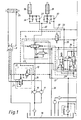
- the hydraulic circuit shown in the drawing is intended for controlling the operation of a container-handling vehicle fitted with a telescopic mast assembly of substantial height, e.g. more than 15m in the extended position.
- Various operating elements are illustrated including a cylinder 25 and associated steer pump 9 for operating the vehicle steering; lift cylinders 18 and 19 for raising and lowering the telescopic mast assembly (which in known manner entrains the lifting carriage along it); tilt cylinders 7 for tilting the mast assembly between its lifting and travelling positions; reach cylinders 6 and side-shift cylinder 5, with their associated control manifold 4; and hydraulic valve 3 for the power-assisted braking circuit.
- These components are all conventional and most of these will not be described in further detail.
- the main components associated with the control system of the invention are hydraulic pumps 10 and 11, lift and lowering valve 14, lift cylinders 18 and 19, auxiliary lowering valve 21, auxiliary lift and lowering valve 24, and joystick controller 30.
- the circuit described is intended for a container-handling vehicle and the carriage in this case supports a gantry having hydraulically-operated twistlocks 28 operable to engage the corner fittings of a container.
- the control system of the invention can be applied to any load-handling vehicle, for example one in which the carriage comprises forks or other load-engaging means such as a "piggy-back" attachment for handling intermodal loads.
- Valve 14, auxiliary lowering valve 21 and auxiliary lift and lowering valve 24 are all operated by servos controlled remotely by joystick controller 30 located in the driver's cab.
- the servos are operated hydraulically but they could be operated by other means, such as electrically.
- the position of these valves determines whether or not hydraulic fluid is fed to, held in, or expelled from lift cylinders 18 and 19.
- An electrical interlock 29 is connected between the servos which control valves 21 and 24 and the twistlocks 28.
- Hydraulic pump 10 is dedicated to lift cylinders 18 and 19 and supplies fluid under pressure to valve 14 via line 12. In the position of this valve which is shown in the drawing, the cylinders are inactive and fluid from pump 10 is diverted back to fluid reservoir 16 via return line 17. Operation of joystick controller 30 to call for raising of the mast and carriage assembly causes valve 14 to move to the right in the drawing, directing fluid from line 12 into line 20 and operating lift cylinders 18 and 19. Movement of joystick controller 30 into the lift position also operates auxiliary lift and lowering valve 24 which is supplied with fluid (when available) by pump 11. The servos are designed such that initial movement of the joystick controller operates valve 24 to provide slow-speed lift under fine control.
- valve 14 Further operation of the joystick causes valve 14 to operate as well, giving full lift flow to cylinders 18 and 19. In this condition, additional lift is supplied by pump 11 if fluid pressure is not being used for steering. Pump 11 supplies steering flow to hand steer pump 9 and thus to steer cylinder 25 via lines 26 and 27 but if some or all of this flow is not required, load sensing flow divider 22 sends fluid via line 23 to auxiliary lift and lowering valve 24 where it is directed via lines 31, 32 and 33 to cylinders 18 and 19 to supplement the flow supplied through line 20.
- the twist-locks 28 will be engaged with the corner fittings of the container being carried and the electrical interlock 29 will automatically disengage the servos controlling auxiliary lowering valve 21 and auxiliary lift and lowering valve 24 so as to prevent these valves from moving into a lowering position.
- operation of the joystick control 30 to call for lowering of the load will cause only valve 14 to operate by moving to the left in the drawing, connecting line 20 to return line 36 and thereby returning fluid from cylinders 18 and 19 to reservoir 16.
- the rate of retraction of cylinders 18 and 19 will be determined by the size of the load and the restrictions 34 built into line 20, but under current legislation this will not exceed 0.6 m/sec with a fully-loaded container.
- a higher lowering speed is achieved where no load is being carried by the vehicle.
- the twist locks 28 are in the disengaged position and the electrical interlock 29 allows operation of both auxiliary lowering valve 21 and auxiliary lift and lowering valve 24.
- lift valve 14 moves to the left as before, and auxiliary valves 21 and 24 are moved upwardly in the drawing into their lowering position.
- This connects lines 32 and 33, via lines 31 and 35, with return line 36 leading to reservoir 16. Since additional return lines are open, lift cylinders 18 and 19 void at a faster rate, and lowering of the mast and carriage assembly is achieved more rapidly.
- the lowering speed is determined by restrictions 37 in lines 32 and 33 but this will be significantly higher than the maximum lowering speed in the loaded condition, for example between 0.8 and 1.4 m/sec and preferably about 1.2 m/sec.
- Restrictions 37 may not be required to control lowering in the unladen condition; instead the return flow may by-pass any check valve, and the carriage lowered as quickly as fluid can be displaced through the valves to the reservoir 16.
- a manual control can be provided to allow the operator to select the rate of descent as required by conditions, and as permitted by current legislation.
- control circuit described herein represents only one possible solution to the control system of the invention.
- a data carrier such as a magnetic card
Landscapes
- Engineering & Computer Science (AREA)
- Transportation (AREA)
- Structural Engineering (AREA)
- Chemical & Material Sciences (AREA)
- Combustion & Propulsion (AREA)
- Civil Engineering (AREA)
- Life Sciences & Earth Sciences (AREA)
- Geology (AREA)
- Mechanical Engineering (AREA)
- Forklifts And Lifting Vehicles (AREA)
- Jib Cranes (AREA)
Applications Claiming Priority (2)
| Application Number | Priority Date | Filing Date | Title |
|---|---|---|---|
| GB9221304A GB2271339B (en) | 1992-10-09 | 1992-10-09 | Control system for load-handling vehicle |
| GB9221304 | 1992-10-09 |
Publications (3)
| Publication Number | Publication Date |
|---|---|
| EP0592235A2 true EP0592235A2 (de) | 1994-04-13 |
| EP0592235A3 EP0592235A3 (en) | 1994-08-10 |
| EP0592235B1 EP0592235B1 (de) | 1999-04-28 |
Family
ID=10723244
Family Applications (1)
| Application Number | Title | Priority Date | Filing Date |
|---|---|---|---|
| EP19930308016 Expired - Lifetime EP0592235B1 (de) | 1992-10-09 | 1993-10-08 | Steuervorrichtung für Lasthandhabungsfahrzeug |
Country Status (4)
| Country | Link |
|---|---|
| EP (1) | EP0592235B1 (de) |
| DE (1) | DE69324642T2 (de) |
| ES (1) | ES2132195T3 (de) |
| GB (1) | GB2271339B (de) |
Cited By (2)
| Publication number | Priority date | Publication date | Assignee | Title |
|---|---|---|---|---|
| EP0644151A1 (de) * | 1993-09-17 | 1995-03-22 | Boss Group Limited | Hydraulischer Steuerkreislauf für einen selbstbetriebenen Hubwagen |
| EP3533752A1 (de) * | 2018-02-28 | 2019-09-04 | Jungheinrich Aktiengesellschaft | Flurförderzeug mit mindestens einem hydraulischen masthubzylinder |
Families Citing this family (1)
| Publication number | Priority date | Publication date | Assignee | Title |
|---|---|---|---|---|
| RU2160696C2 (ru) * | 1997-10-31 | 2000-12-20 | Стесин Александр Борисович | Гидравлическая система вилочного автопогрузчика |
Family Cites Families (9)
| Publication number | Priority date | Publication date | Assignee | Title |
|---|---|---|---|---|
| US3285282A (en) * | 1964-10-22 | 1966-11-15 | Parker Hannifin Corp | Flow control valve for fluid motors and the like |
| US3414007A (en) * | 1965-04-19 | 1968-12-03 | Fluid Controls Inc | Load lowering valve for hydraulic hoists |
| US3685537A (en) * | 1970-04-14 | 1972-08-22 | Shimadzu Corp | Fluid flow control valve |
| DE2227823C3 (de) * | 1972-06-08 | 1975-10-16 | Friedrich Kocks Gmbh, 2800 Bremen | Ladegeschirr für Container |
| US4111283A (en) * | 1976-12-20 | 1978-09-05 | Clark Equipment Company | Regulator valve |
| JPS63230497A (ja) * | 1987-03-20 | 1988-09-26 | 日産自動車株式会社 | 産業車両の荷役装置 |
| US4716929A (en) * | 1987-05-04 | 1988-01-05 | B. W. Rogers Company | Flow control valve |
| JPH03159879A (ja) * | 1989-11-20 | 1991-07-09 | Toyota Autom Loom Works Ltd | 産業車両の荷役制御装置 |
| JP2668754B2 (ja) * | 1991-12-25 | 1997-10-27 | 小松フォークリフト株式会社 | 産業車両の荷役制御方法 |
-
1992
- 1992-10-09 GB GB9221304A patent/GB2271339B/en not_active Expired - Fee Related
-
1993
- 1993-10-08 DE DE1993624642 patent/DE69324642T2/de not_active Expired - Fee Related
- 1993-10-08 ES ES93308016T patent/ES2132195T3/es not_active Expired - Lifetime
- 1993-10-08 EP EP19930308016 patent/EP0592235B1/de not_active Expired - Lifetime
Cited By (3)
| Publication number | Priority date | Publication date | Assignee | Title |
|---|---|---|---|---|
| EP0644151A1 (de) * | 1993-09-17 | 1995-03-22 | Boss Group Limited | Hydraulischer Steuerkreislauf für einen selbstbetriebenen Hubwagen |
| EP3533752A1 (de) * | 2018-02-28 | 2019-09-04 | Jungheinrich Aktiengesellschaft | Flurförderzeug mit mindestens einem hydraulischen masthubzylinder |
| US11377334B2 (en) | 2018-02-28 | 2022-07-05 | Jungheinrich Aktiengesellschaft | Industrial truck with at least one hydraulic mast lift cylinder |
Also Published As
| Publication number | Publication date |
|---|---|
| GB2271339A (en) | 1994-04-13 |
| GB2271339B (en) | 1996-05-08 |
| DE69324642D1 (de) | 1999-06-02 |
| EP0592235A3 (en) | 1994-08-10 |
| GB9221304D0 (en) | 1992-11-25 |
| EP0592235B1 (de) | 1999-04-28 |
| DE69324642T2 (de) | 1999-09-30 |
| ES2132195T3 (es) | 1999-08-16 |
Similar Documents
| Publication | Publication Date | Title |
|---|---|---|
| US11905153B2 (en) | Industrial truck, hydraulic system for an industrial truck and method for operating a hydraulic system | |
| US5238086A (en) | Control device for forklift | |
| EP2881358B1 (de) | Flurförderzeug | |
| EP2805911B1 (de) | Flurförderzeug, insbesondere Kommissionierflurförderzeug mit einem anhebbaren und absenkbaren Fahrerstand | |
| US7735586B2 (en) | Industrial truck | |
| US4274795A (en) | Load carrying vehicles | |
| CA1054979A (en) | Combined lift-pallet truck | |
| US2833435A (en) | Materials-handling vehicle | |
| US5791860A (en) | Hydraulic platform lift for a truck tailgate | |
| US11926514B1 (en) | Forklift | |
| EP0592235B1 (de) | Steuervorrichtung für Lasthandhabungsfahrzeug | |
| US5088879A (en) | Forward tilt limit system for lift trucks | |
| EP0027811B1 (de) | Lastwagen zum heben und transportieren eines containers | |
| US3099332A (en) | Elevating shelf for stock bin servicing truck | |
| RU2160696C2 (ru) | Гидравлическая система вилочного автопогрузчика | |
| GB1582754A (en) | Loadcarrying vehicles | |
| JP3681298B2 (ja) | 高所作業車の過積載作動規制装置 | |
| JP3075006B2 (ja) | フォークリフトの昇降制御方法 | |
| JP2000355497A (ja) | フォークリフトトラックの荷役用シリンダの制御装置 | |
| CN217502120U (zh) | 一种二级伸缩装置 | |
| EP2674386B1 (de) | Gabelstapler mit lastabhängigem Antriebsraddruck | |
| KR200234029Y1 (ko) | 화물차의 받침목 이동장치 | |
| JP2706379B2 (ja) | 作業機械の走行時での機能停止装置 | |
| JP3240802B2 (ja) | オーダーピッカーの昇降速度調整装置 | |
| JP3028309B1 (ja) | 荷役作業車 |
Legal Events
| Date | Code | Title | Description |
|---|---|---|---|
| PUAI | Public reference made under article 153(3) epc to a published international application that has entered the european phase |
Free format text: ORIGINAL CODE: 0009012 |
|
| AK | Designated contracting states |
Kind code of ref document: A2 Designated state(s): DE ES FR GB IT NL SE |
|
| PUAL | Search report despatched |
Free format text: ORIGINAL CODE: 0009013 |
|
| AK | Designated contracting states |
Kind code of ref document: A3 Designated state(s): DE ES FR GB IT NL SE |
|
| 17P | Request for examination filed |
Effective date: 19950116 |
|
| RAP1 | Party data changed (applicant data changed or rights of an application transferred) |
Owner name: BOSS GROUP LIMITED |
|
| RAP3 | Party data changed (applicant data changed or rights of an application transferred) |
Owner name: BOSS GROUP LIMITED |
|
| 17Q | First examination report despatched |
Effective date: 19970902 |
|
| GRAG | Despatch of communication of intention to grant |
Free format text: ORIGINAL CODE: EPIDOS AGRA |
|
| GRAG | Despatch of communication of intention to grant |
Free format text: ORIGINAL CODE: EPIDOS AGRA |
|
| GRAH | Despatch of communication of intention to grant a patent |
Free format text: ORIGINAL CODE: EPIDOS IGRA |
|
| GRAH | Despatch of communication of intention to grant a patent |
Free format text: ORIGINAL CODE: EPIDOS IGRA |
|
| GRAA | (expected) grant |
Free format text: ORIGINAL CODE: 0009210 |
|
| AK | Designated contracting states |
Kind code of ref document: B1 Designated state(s): DE ES FR GB IT NL SE |
|
| ITF | It: translation for a ep patent filed | ||
| REF | Corresponds to: |
Ref document number: 69324642 Country of ref document: DE Date of ref document: 19990602 |
|
| ET | Fr: translation filed | ||
| REG | Reference to a national code |
Ref country code: ES Ref legal event code: FG2A Ref document number: 2132195 Country of ref document: ES Kind code of ref document: T3 |
|
| PLBE | No opposition filed within time limit |
Free format text: ORIGINAL CODE: 0009261 |
|
| 26N | No opposition filed | ||
| PGFP | Annual fee paid to national office [announced via postgrant information from national office to epo] |
Ref country code: GB Payment date: 20011008 Year of fee payment: 9 |
|
| PGFP | Annual fee paid to national office [announced via postgrant information from national office to epo] |
Ref country code: ES Payment date: 20011016 Year of fee payment: 9 |
|
| PGFP | Annual fee paid to national office [announced via postgrant information from national office to epo] |
Ref country code: FR Payment date: 20011017 Year of fee payment: 9 |
|
| PGFP | Annual fee paid to national office [announced via postgrant information from national office to epo] |
Ref country code: SE Payment date: 20011019 Year of fee payment: 9 |
|
| PGFP | Annual fee paid to national office [announced via postgrant information from national office to epo] |
Ref country code: NL Payment date: 20011031 Year of fee payment: 9 Ref country code: DE Payment date: 20011031 Year of fee payment: 9 |
|
| REG | Reference to a national code |
Ref country code: GB Ref legal event code: 732E |
|
| NLS | Nl: assignments of ep-patents |
Owner name: BOSS UK HOLDING COMPANY LIMITED |
|
| NLT1 | Nl: modifications of names registered in virtue of documents presented to the patent office pursuant to art. 16 a, paragraph 1 |
Owner name: BOSS MANUFACTURING LIMITED |
|
| REG | Reference to a national code |
Ref country code: GB Ref legal event code: IF02 |
|
| PG25 | Lapsed in a contracting state [announced via postgrant information from national office to epo] |
Ref country code: GB Free format text: LAPSE BECAUSE OF NON-PAYMENT OF DUE FEES Effective date: 20021008 |
|
| PG25 | Lapsed in a contracting state [announced via postgrant information from national office to epo] |
Ref country code: SE Free format text: LAPSE BECAUSE OF NON-PAYMENT OF DUE FEES Effective date: 20021009 Ref country code: ES Free format text: LAPSE BECAUSE OF NON-PAYMENT OF DUE FEES Effective date: 20021009 |
|
| PG25 | Lapsed in a contracting state [announced via postgrant information from national office to epo] |
Ref country code: NL Free format text: LAPSE BECAUSE OF NON-PAYMENT OF DUE FEES Effective date: 20030501 Ref country code: DE Free format text: LAPSE BECAUSE OF NON-PAYMENT OF DUE FEES Effective date: 20030501 |
|
| GBPC | Gb: european patent ceased through non-payment of renewal fee |
Effective date: 20021008 |
|
| EUG | Se: european patent has lapsed | ||
| PG25 | Lapsed in a contracting state [announced via postgrant information from national office to epo] |
Ref country code: FR Free format text: LAPSE BECAUSE OF NON-PAYMENT OF DUE FEES Effective date: 20030630 |
|
| NLV4 | Nl: lapsed or anulled due to non-payment of the annual fee |
Effective date: 20030501 |
|
| REG | Reference to a national code |
Ref country code: FR Ref legal event code: ST |
|
| REG | Reference to a national code |
Ref country code: ES Ref legal event code: FD2A Effective date: 20031112 |
|
| PG25 | Lapsed in a contracting state [announced via postgrant information from national office to epo] |
Ref country code: IT Free format text: LAPSE BECAUSE OF NON-PAYMENT OF DUE FEES;WARNING: LAPSES OF ITALIAN PATENTS WITH EFFECTIVE DATE BEFORE 2007 MAY HAVE OCCURRED AT ANY TIME BEFORE 2007. THE CORRECT EFFECTIVE DATE MAY BE DIFFERENT FROM THE ONE RECORDED. Effective date: 20051008 |