EP0592059B1 - Verfahren und Vorrichtung zum Verdichten von Luft - Google Patents
Verfahren und Vorrichtung zum Verdichten von Luft Download PDFInfo
- Publication number
- EP0592059B1 EP0592059B1 EP93250248A EP93250248A EP0592059B1 EP 0592059 B1 EP0592059 B1 EP 0592059B1 EP 93250248 A EP93250248 A EP 93250248A EP 93250248 A EP93250248 A EP 93250248A EP 0592059 B1 EP0592059 B1 EP 0592059B1
- Authority
- EP
- European Patent Office
- Prior art keywords
- steam
- waste
- compressor
- turbo charger
- gas
- Prior art date
- Legal status (The legal status is an assumption and is not a legal conclusion. Google has not performed a legal analysis and makes no representation as to the accuracy of the status listed.)
- Expired - Lifetime
Links
Images


Classifications
-
- F—MECHANICAL ENGINEERING; LIGHTING; HEATING; WEAPONS; BLASTING
- F02—COMBUSTION ENGINES; HOT-GAS OR COMBUSTION-PRODUCT ENGINE PLANTS
- F02C—GAS-TURBINE PLANTS; AIR INTAKES FOR JET-PROPULSION PLANTS; CONTROLLING FUEL SUPPLY IN AIR-BREATHING JET-PROPULSION PLANTS
- F02C6/00—Plural gas-turbine plants; Combinations of gas-turbine plants with other apparatus; Adaptations of gas-turbine plants for special use
- F02C6/04—Gas-turbine plants providing heated or pressurised working fluid for other apparatus, e.g. without mechanical power output
- F02C6/06—Gas-turbine plants providing heated or pressurised working fluid for other apparatus, e.g. without mechanical power output providing compressed gas
-
- F—MECHANICAL ENGINEERING; LIGHTING; HEATING; WEAPONS; BLASTING
- F01—MACHINES OR ENGINES IN GENERAL; ENGINE PLANTS IN GENERAL; STEAM ENGINES
- F01K—STEAM ENGINE PLANTS; STEAM ACCUMULATORS; ENGINE PLANTS NOT OTHERWISE PROVIDED FOR; ENGINES USING SPECIAL WORKING FLUIDS OR CYCLES
- F01K23/00—Plants characterised by more than one engine delivering power external to the plant, the engines being driven by different fluids
- F01K23/02—Plants characterised by more than one engine delivering power external to the plant, the engines being driven by different fluids the engine cycles being thermally coupled
- F01K23/06—Plants characterised by more than one engine delivering power external to the plant, the engines being driven by different fluids the engine cycles being thermally coupled combustion heat from one cycle heating the fluid in another cycle
- F01K23/065—Plants characterised by more than one engine delivering power external to the plant, the engines being driven by different fluids the engine cycles being thermally coupled combustion heat from one cycle heating the fluid in another cycle the combustion taking place in an internal combustion piston engine, e.g. a diesel engine
-
- F—MECHANICAL ENGINEERING; LIGHTING; HEATING; WEAPONS; BLASTING
- F01—MACHINES OR ENGINES IN GENERAL; ENGINE PLANTS IN GENERAL; STEAM ENGINES
- F01N—GAS-FLOW SILENCERS OR EXHAUST APPARATUS FOR MACHINES OR ENGINES IN GENERAL; GAS-FLOW SILENCERS OR EXHAUST APPARATUS FOR INTERNAL-COMBUSTION ENGINES
- F01N5/00—Exhaust or silencing apparatus combined or associated with devices profiting by exhaust energy
- F01N5/02—Exhaust or silencing apparatus combined or associated with devices profiting by exhaust energy the devices using heat
-
- F—MECHANICAL ENGINEERING; LIGHTING; HEATING; WEAPONS; BLASTING
- F01—MACHINES OR ENGINES IN GENERAL; ENGINE PLANTS IN GENERAL; STEAM ENGINES
- F01N—GAS-FLOW SILENCERS OR EXHAUST APPARATUS FOR MACHINES OR ENGINES IN GENERAL; GAS-FLOW SILENCERS OR EXHAUST APPARATUS FOR INTERNAL-COMBUSTION ENGINES
- F01N5/00—Exhaust or silencing apparatus combined or associated with devices profiting by exhaust energy
- F01N5/04—Exhaust or silencing apparatus combined or associated with devices profiting by exhaust energy the devices using kinetic energy
-
- F—MECHANICAL ENGINEERING; LIGHTING; HEATING; WEAPONS; BLASTING
- F02—COMBUSTION ENGINES; HOT-GAS OR COMBUSTION-PRODUCT ENGINE PLANTS
- F02C—GAS-TURBINE PLANTS; AIR INTAKES FOR JET-PROPULSION PLANTS; CONTROLLING FUEL SUPPLY IN AIR-BREATHING JET-PROPULSION PLANTS
- F02C6/00—Plural gas-turbine plants; Combinations of gas-turbine plants with other apparatus; Adaptations of gas-turbine plants for special use
- F02C6/18—Plural gas-turbine plants; Combinations of gas-turbine plants with other apparatus; Adaptations of gas-turbine plants for special use using the waste heat of gas-turbine plants outside the plants themselves, e.g. gas-turbine power heat plants
-
- F—MECHANICAL ENGINEERING; LIGHTING; HEATING; WEAPONS; BLASTING
- F04—POSITIVE - DISPLACEMENT MACHINES FOR LIQUIDS; PUMPS FOR LIQUIDS OR ELASTIC FLUIDS
- F04B—POSITIVE-DISPLACEMENT MACHINES FOR LIQUIDS; PUMPS
- F04B35/00—Piston pumps specially adapted for elastic fluids and characterised by the driving means to their working members, or by combination with, or adaptation to, specific driving engines or motors, not otherwise provided for
- F04B35/002—Piston pumps specially adapted for elastic fluids and characterised by the driving means to their working members, or by combination with, or adaptation to, specific driving engines or motors, not otherwise provided for driven by internal combustion engines
-
- F—MECHANICAL ENGINEERING; LIGHTING; HEATING; WEAPONS; BLASTING
- F04—POSITIVE - DISPLACEMENT MACHINES FOR LIQUIDS; PUMPS FOR LIQUIDS OR ELASTIC FLUIDS
- F04B—POSITIVE-DISPLACEMENT MACHINES FOR LIQUIDS; PUMPS
- F04B41/00—Pumping installations or systems specially adapted for elastic fluids
- F04B41/06—Combinations of two or more pumps
-
- F—MECHANICAL ENGINEERING; LIGHTING; HEATING; WEAPONS; BLASTING
- F04—POSITIVE - DISPLACEMENT MACHINES FOR LIQUIDS; PUMPS FOR LIQUIDS OR ELASTIC FLUIDS
- F04D—NON-POSITIVE-DISPLACEMENT PUMPS
- F04D25/00—Pumping installations or systems
- F04D25/02—Units comprising pumps and their driving means
- F04D25/04—Units comprising pumps and their driving means the pump being fluid-driven
-
- F—MECHANICAL ENGINEERING; LIGHTING; HEATING; WEAPONS; BLASTING
- F02—COMBUSTION ENGINES; HOT-GAS OR COMBUSTION-PRODUCT ENGINE PLANTS
- F02B—INTERNAL-COMBUSTION PISTON ENGINES; COMBUSTION ENGINES IN GENERAL
- F02B1/00—Engines characterised by fuel-air mixture compression
- F02B1/02—Engines characterised by fuel-air mixture compression with positive ignition
- F02B1/04—Engines characterised by fuel-air mixture compression with positive ignition with fuel-air mixture admission into cylinder
-
- Y—GENERAL TAGGING OF NEW TECHNOLOGICAL DEVELOPMENTS; GENERAL TAGGING OF CROSS-SECTIONAL TECHNOLOGIES SPANNING OVER SEVERAL SECTIONS OF THE IPC; TECHNICAL SUBJECTS COVERED BY FORMER USPC CROSS-REFERENCE ART COLLECTIONS [XRACs] AND DIGESTS
- Y02—TECHNOLOGIES OR APPLICATIONS FOR MITIGATION OR ADAPTATION AGAINST CLIMATE CHANGE
- Y02T—CLIMATE CHANGE MITIGATION TECHNOLOGIES RELATED TO TRANSPORTATION
- Y02T10/00—Road transport of goods or passengers
- Y02T10/10—Internal combustion engine [ICE] based vehicles
- Y02T10/12—Improving ICE efficiencies
Definitions
- the invention relates to a method and a device for compressing air.
- Compressed air is required for the operation of portable compressed gas consumers and work equipment, such as in construction.
- it is particularly advisable for commercial users of large consumers of energy to save proportionate energy by improving the efficiency of the method used and the machines and systems used.
- various attempts have been made to use process waste heat generated internally and externally in order to improve the energy balance and thus increase the overall efficiency.
- a multi-stage compressor is known, between whose individual compressor stages coolers are provided, which are an integral part of a heat pump (DE-OS 31 34 844).
- the heat of compression generated in the process is converted into heat that can be used externally. Internal use of the heat provided in this way is not intended. Although this improves the energy balance of the compressor arrangement, external processes are required to make use of the recovered energy. This form of efficiency improvement is not practical for an autonomous portable compressor.
- EP-0162368 A2 Another method for compressing air and an associated device are disclosed in EP-0162368 A2.
- a thermal energy generation system is combined with an air separation system.
- the latter system consists of a gas turbine, the utility side of which is connected to a compressor.
- the exhaust gas from the gas turbine is fed to a waste heat boiler, where it is burned or afterburned with the addition of fuel.
- the heat generated is transferred to a closed liquid-steam cycle, the superheated steam being fed to two steam turbines operating in parallel.
- the useful sides of both steam turbines are each connected to a compressor, one turbo set acting as post-compression for the injection gas and the second turbo set operating the air separation unit.
- a disadvantage of this process concept is the large amount of equipment with the associated complex control and regulating device, so that the associated device is not suitable as a mobile system.
- the aim of the invention is, based on the known methods, to provide an improved method for compressing a gaseous medium, in particular air, in order to increase the overall efficiency of mobile compressor systems.
- the overall efficiency is the ratio of the drive energy required to the compressed gas volume.
- the process according to the invention is characterized in that, with the exhaust gas stream of a heat engine driving a compressor, a liquid of a closed or open liquid-steam cycle system evaporates and overheats and the superheated steam is fed to the drive side of a turbocharger in the form of a steam turbocharger.
- a liquid of a closed or open liquid-steam cycle system evaporates and overheats and the superheated steam is fed to the drive side of a turbocharger in the form of a steam turbocharger.
- a high exhaust gas back pressure means a higher push-out work and thus loss of performance, which is synonymous with a reduction in the drive power for the compressor.
- the maximum power for the heat engine is reached when the heat engine pushes against the lowest possible exhaust gas back pressure, ie against atmospheric pressure.
- the exhaust gas heat exchanger or evaporator arranged in the liquid-steam cycle system causes only a very small, generally negligible exhaust gas build-up and also assumes a muffler function. This means that the proposed method advantageously pre-compresses and / or post-compresses the gaseous medium to be compressed by the steam turbocharger without any significant effect on the heat engine, thereby increasing the overall efficiency.
- the basic procedure can be varied depending on the system design and design.
- the steam flow can be divided and a partial flow can be fed to the drive side of several, preferably two, turbochargers for pre-compression and post-compression.
- the division of the steam flow can alternatively or additionally be used for the regulation, in that a partial flow is switched on or off as a bypass.
- a series connection is also possible, in which the steam flow is successively fed to the drive side of a plurality of turbochargers.
- Another variant results in the exhaust gas flow being used for intermediate heating after the liquid has evaporated.
- the steam flow is passed through a heat exchanger after leaving the first steam turbocharger, which is also acted upon by the exhaust gas flow.
- the exhaust gas turbocharger is used as a pre-compression unit and the steam turbocharger as a post-compression unit. Taking into account the statements made above, however, it may be advantageous first to act with the exhaust gas flow on the liquid / steam cycle system and then to act on the drive side of the exhaust gas turbocharger.
- the compressor in question is basically a compressor of any type that is suitable for compressing a gas.
- This preferably includes all compressors with variable compression space, e.g. Piston and screw compressors, but also all compressors that use a different compression system, e.g. Turbocompressors work.
- the mentioned heat engine is a reciprocating piston machine, e.g. Diesel and petrol engines as well as rotary lobe machines and gas turbines of all kinds.
- the gas to be compressed is in particular air, but also any other gaseous medium that is suitable for compression.
- Suitable steam turbochargers are in particular those with a radial impeller on the compressor side and tangential impeller on the turbine side, but also any other suitable impeller shape.
- At least one steam turbocharger is provided.
- This steam turbocharger is optionally arranged upstream and / or downstream of the compressor for pre-compression and / or post-compression and is operated with the exhaust gas of the heat engine insofar as the energy content of the exhaust gas is used in that an energy exchange between exhaust gas and liquid, preferably water or liquid vapor, takes place in a heat exchanger. It is particularly advantageous both to precompress and to recompress the gas to be compressed, the overall efficiency being further improved as a result of the lower compression ratio of each individual compression stage.
- Heat exchangers of any kind are suitable as intercoolers, which are suitable for cooling a gas, in particular for air.
- the ambient air comes into consideration as the cooling medium as well as all other media suitable for cooling in the open as well as in the closed system.
- the proposed method can be used in an advantageous manner for all types of compressors, in particular for dry-running machines, since the compression ratio for the main compression unit can be selected to be lower due to the pre-compression and post-compression. This means that, depending on the required compression ratio or final operating pressure, the main compression unit can be equipped with fewer compression stages, thus achieving less expensive production.
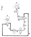
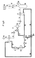
- a compressor 50 is connected on the user side to a known heat engine 40.
- This compressor 50 generates a pressure difference P2 between its inlet and its outlet.
- the exhaust side of the heat engine 40 is connected to an evaporator 14 via an exhaust line 41.
- a liquid, preferably water is pressed into the evaporator with the aid of a feed water pump 13 and a connecting line 62.
- the liquid evaporated in the evaporator 14 by the exhaust gas energy flows in the form of steam through the steam line 90 to the turbine side of the steam turbocharger 20.
- the steam relaxes there and flows over the Steam line 91 into a condenser 11 and is condensed there.
- the liquid liquefied in the condenser reaches the storage container 12 via the connecting line 60.
- the liquid reaches the feed water pump 13 again via a further connecting line 61.
- the compressor part of the steam turbocharger 20 generates a pressure difference P1. This ensures that both the useful energy of the heat engine 40 with the aid of the compressor 50 and the exhaust gas energy of the heat engine 40 with the help of the steam turbocharger 20 are converted into the target variable pressure difference or compression ratio.
- the total pressure difference of the compressor system is the sum of all pressure differences, in this case P1 + P2.
- the order of the compressor stages is in principle irrelevant.
- a given energy is required for a given compressor arrangement, which energy can be taken from the given heat engine 40 as a constant variable.
- the overall efficiency of the compressor system is now greater because of the greater compression ratio and the waste heat generated is usefully used in the internal process.
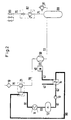
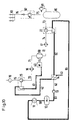
- the gas to be compressed is cleaned by the filter 10 and sucked in by the steam turbocharger 21 through the suction line 15.
- the pre-compressed gas is then supplied to the compressor 50 through the pressure line 70.
- the heat engine 40 is used to drive the compressor 50.
- the exhaust gas of the heat engine 40 is fed to the evaporator 14 through the exhaust gas line 41 and then discharged from the evaporator 14 via the exhaust gas line 42.
- water is pressed into the evaporator with the aid of a feed water pump 13 and a connecting line 62. That in the evaporator 14 through the Exhaust gas energy evaporated water flows in the form of water vapor through the steam line 90 to the turbine side of the steam turbocharger 21.
- the water vapor relaxes and flows via the steam line 91 into a condenser 11 and is condensed there.
- the water liquefied in the condenser reaches the storage container 12 via the connecting line 60.
- the water returns to the feed water pump 13 via a further connecting line 61.
- the compressed gas from the compressor 50 reaches the pressure container 80 via the pressure line 72.
- the pressure container 80 is passed through the safety valve 81 monitors. From the pressure vessel 80, the compressed gas passes through the pressure line 75 via the pressure-holding check valve 82 and through the pressure line 76 to the taps 83.
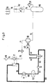
- the intercooler 16 is provided in FIG. 3 between the steam turbocharger 21 and the compressor 50. This intercooler 16 cools the pre-compressed gas and lowers the power requirement of the compressor system.
- the pressure line 71 is provided for connecting the intercooler 16 to the compressor 50.
- the steam turbocharger 22 is arranged behind the compressor 50 in order to recompress the gas flowing out of the compressor 50.
- the heat engine 40 is used to drive the compressor 50.
- the exhaust gas of the heat engine 40 is fed to the evaporator 14 through the exhaust gas line 41 and then discharged from the evaporator 14 via the exhaust gas line 42.
- the water evaporated in the evaporator 14 by the exhaust gas energy flows in the form of water vapor through the steam line 92 to the turbine side of the steam turbocharger 22. There, the water vapor relaxes and flows via the steam line 93 into a condenser 11 and is condensed there.
- the pressure line 73 is provided for connecting the steam turbocharger 22 to the pressure vessel 80.
- the intercooler 17 is provided in FIG Reduce the power requirement of the compressor system.
- the pressure line 74 is provided for connecting the intercooler 17 to the steam turbocharger 22.
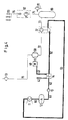
- a compressor system is shown in FIG. 6, in which a steam turbocharger 21 and 22 is provided both in front of and behind the compressor 50.
- the turbine side of the post-compression steam turbocharger 22 is first applied via the steam line 92 and then the turbine side of the pre-compression steam turbocharger 21 via the steam line 95. that the steam line 92 is first connected to the turbine side of the pre-compressing steam turbocharger 21.
- an intercooler 16 is additionally arranged behind the first steam turbocharger 21 and an intercooler 17 is additionally arranged behind the compressor 50 in order to further reduce the overall power consumption of the compressor.
- Each intercooler 16 and 17 provided can optionally be provided with a condensate drain.
- FIG. 7 shows an arrangement similar to that of FIG. 6, with the only difference that the steam flow is divided after the evaporator 14.
- the two exhausting steam lines 93, 91 reunite.
- the idea of dividing the steam flow can also be used for the control, for example by using the steam line 90 as a bypass line that can be switched on and off. In this case, it would then not be connected to the turbine side of the pre-compressing steam turbocharger 22, but would open before the condenser 11. This would have the advantage of being able to add steam can regulate to the two steam turbochargers 21, 22 depending on the requirement, for example at partial load.
- an intermediate heater 18 is additionally placed in FIG. 8 between the two steam turbochargers 21 and 22.
- the exhaust gas from the heat engine 40 which has been partially cooled in the evaporator 14, is fed to the intermediate heater 18 through the exhaust gas line 42 and further cooled.
- the exhaust gas is then discharged via the exhaust line 43.
- the reheated steam is supplied to the steam turbocharger 21 via the steam line 96.
- the advantage of this embodiment is that the steam turbocharger 21 is supplied with a steam at a higher temperature, which has a higher usable energy content and thus leads to an increase in performance in the steam turbocharger 21.
- the waste heat from the oil and / or cooling circuit of the heat engine 40 is also used.
- hinted oil or cooling water from the heat engine 40 is fed via the line 48 shown in broken lines to a heat exchanger 19 which is arranged between the feed water pump 13 and the evaporator 14.
- the cooled oil or water is returned to the heat engine 40 via the line 49, which is also shown in broken lines.
- This arrangement has the advantage that both the oil cooler and the cooler for the cooling water can be designed to be structurally small, since part of the stored heat is removed from the heat exchanger 19.
- the heat supply leads to preheating of the water under pressure and thus to a thermal improvement of the circuit.
- FIG. 10 shows a further embodiment of the invention, in which the use of an exhaust gas turbocharger, which is known per se, is combined with a steam turbocharger according to the invention.
- the turbine side of the exhaust gas turbocharger 25 is acted upon via the exhaust line 41 and then the evaporator 14 of the closed liquid-steam cycle system via the exhaust line 42. It is also possible to reverse the sequence, that is to say that first the evaporator 14 and then the turbine side of the exhaust gas turbocharger 25 are acted upon. It is irrelevant whether the exhaust gas turbocharger 25 is arranged as a pre-compressing or post-compressing unit. Both arrangements have the advantage that both the stored kinetic and the thermal energy are largely used by the exhaust gas flow.
Landscapes
- Engineering & Computer Science (AREA)
- Mechanical Engineering (AREA)
- General Engineering & Computer Science (AREA)
- Chemical & Material Sciences (AREA)
- Combustion & Propulsion (AREA)
- Supercharger (AREA)
- Engine Equipment That Uses Special Cycles (AREA)
- Separation By Low-Temperature Treatments (AREA)
Applications Claiming Priority (2)
| Application Number | Priority Date | Filing Date | Title |
|---|---|---|---|
| DE4234393A DE4234393C1 (enExample) | 1992-10-07 | 1992-10-07 | |
| DE4234393 | 1992-10-07 |
Publications (2)
| Publication Number | Publication Date |
|---|---|
| EP0592059A1 EP0592059A1 (de) | 1994-04-13 |
| EP0592059B1 true EP0592059B1 (de) | 1997-12-10 |
Family
ID=6470292
Family Applications (1)
| Application Number | Title | Priority Date | Filing Date |
|---|---|---|---|
| EP93250248A Expired - Lifetime EP0592059B1 (de) | 1992-10-07 | 1993-09-13 | Verfahren und Vorrichtung zum Verdichten von Luft |
Country Status (8)
| Country | Link |
|---|---|
| US (1) | US5461861A (enExample) |
| EP (1) | EP0592059B1 (enExample) |
| JP (1) | JPH0771242A (enExample) |
| CN (1) | CN1053258C (enExample) |
| AT (1) | ATE161072T1 (enExample) |
| CA (1) | CA2107300A1 (enExample) |
| DE (2) | DE4234393C1 (enExample) |
| ES (1) | ES2112963T3 (enExample) |
Families Citing this family (17)
| Publication number | Priority date | Publication date | Assignee | Title |
|---|---|---|---|---|
| US6551076B2 (en) * | 2000-12-15 | 2003-04-22 | Jim L. Boulware | Fuel/hydraulic engine system |
| DE10238435A1 (de) * | 2002-08-16 | 2004-02-19 | Linde Ag | Verfahren und Vorrichtung zum Erzeugen eines verdichteten Gasstroms |
| WO2004074641A1 (ja) * | 2003-02-21 | 2004-09-02 | Hitachi, Ltd. | ガス圧縮機 |
| IL157887A (en) | 2003-09-11 | 2006-08-01 | Ormat Ind Ltd | Method and apparatus for augmenting the pressure head of gas flowing in a pipeline |
| BE1017317A3 (nl) * | 2006-06-01 | 2008-06-03 | Atlas Copco Airpower Nv | Verbeterde compressorinrichting. |
| US8449270B2 (en) * | 2008-04-02 | 2013-05-28 | Frank Michael Washko | Hydraulic powertrain system |
| DE102010014833B4 (de) * | 2010-04-12 | 2012-08-30 | Dieter Lang | Vorrichtung zur thermischen Kopplung von Dampfkraftwerken mit Druckluftspeicherkraftwerken |
| CN103016114A (zh) * | 2011-12-30 | 2013-04-03 | 摩尔动力(北京)技术股份有限公司 | 内燃机排气余热动力系统 |
| WO2013158065A1 (en) * | 2012-04-16 | 2013-10-24 | International Engine Intellectual Property Company, Llc | Turbocharger turbine booster |
| JP5778849B1 (ja) * | 2014-12-22 | 2015-09-16 | 三井造船株式会社 | 動力装置 |
| DE102015204466A1 (de) | 2015-03-12 | 2016-09-15 | Siemens Aktiengesellschaft | Anordnung mit zwei Verdichtern, Verfahren zum Nachrüsten |
| US12049899B2 (en) | 2017-08-28 | 2024-07-30 | Mark J. Maynard | Systems and methods for improving the performance of air-driven generators using solar thermal heating |
| US12270404B2 (en) | 2017-08-28 | 2025-04-08 | Mark J. Maynard | Gas-driven generator system comprising an elongate gravitational distribution conduit coupled with a gas injection system |
| MX2020007639A (es) * | 2018-01-18 | 2020-09-14 | Mark J Maynard | Compresión de fluidos gaseosos con refrigeración alterna y compresión mecánica. |
| KR102016415B1 (ko) * | 2018-03-09 | 2019-08-30 | 삼성중공업 주식회사 | 압축 공기 생성 장치 |
| CN111120066A (zh) * | 2018-11-01 | 2020-05-08 | 上海汽车集团股份有限公司 | 车辆及其发动机冷却系统 |
| WO2023196637A1 (en) | 2022-04-08 | 2023-10-12 | Maynard Mark J | Systems and methods of using cascading heat pumps for improvement of coefficient of performance |
Family Cites Families (13)
| Publication number | Priority date | Publication date | Assignee | Title |
|---|---|---|---|---|
| DE701457C (de) * | 1936-05-29 | 1941-01-16 | Rheinmetall Borsig Akt Ges | Einrichtung zur Energiegewinnung aus den Abgasen von Verbrennungskraftmaschinen |
| US2849173A (en) * | 1956-01-31 | 1958-08-26 | Charles J Surdy | Compressor system |
| US3705491A (en) * | 1970-06-30 | 1972-12-12 | Richard W Foster Pegg | Jet engine air compressor |
| DE2102770A1 (de) * | 1971-01-21 | 1972-08-03 | Rastalsky O | Anlage einer Gasturbine mit Energiespeicherung gebunden mit einer Dampfturbine |
| FR2250390A5 (enExample) * | 1973-10-31 | 1975-05-30 | Zimmern Bernard | |
| DE2821154A1 (de) * | 1978-05-13 | 1980-04-17 | Volkswagenwerk Ag | Abgasturbolader fuer brennkraftmaschinen |
| DE2912190A1 (de) * | 1979-03-28 | 1980-10-02 | Maschf Augsburg Nuernberg Ag | Anordnung eines luftpressers bei einer mehrzylinder-hubkolben-brennkraftmaschine |
| DE3000044A1 (de) * | 1979-11-15 | 1981-05-21 | Robert H. Bronxville N.Y. Johnson | Verfahren und vorrichtung zur rueckgewinnung von verlustenegie aus der kombination eines gaskompressors und eines antriebsmotors fuer den kompressor |
| DD155194A1 (de) * | 1980-12-09 | 1982-05-19 | Artur Wilda | Verfahren zur energetischen optimierung eines verdichtungsprozesses |
| DE3418699A1 (de) * | 1984-05-19 | 1985-11-21 | LGA Gastechnik GmbH, 5480 Remagen | Vorrichtung zur erzeugung von injektionsgas, vorzugsweise zum austreiben von erdoel aus lagerstaetten |
| JPS62284918A (ja) * | 1986-06-02 | 1987-12-10 | Tonen Sekiyukagaku Kk | 高温高圧ガスの製造方法及び装置 |
| US4901531A (en) * | 1988-01-29 | 1990-02-20 | Cummins Engine Company, Inc. | Rankine-diesel integrated system |
| DE4123208C2 (de) * | 1991-07-10 | 1996-07-11 | Mannesmann Ag | Verdichteranlage |
-
1992
- 1992-10-07 DE DE4234393A patent/DE4234393C1/de not_active Expired - Fee Related
-
1993
- 1993-09-13 AT AT93250248T patent/ATE161072T1/de not_active IP Right Cessation
- 1993-09-13 EP EP93250248A patent/EP0592059B1/de not_active Expired - Lifetime
- 1993-09-13 ES ES93250248T patent/ES2112963T3/es not_active Expired - Lifetime
- 1993-09-13 DE DE59307815T patent/DE59307815D1/de not_active Expired - Fee Related
- 1993-09-29 CA CA002107300A patent/CA2107300A1/en not_active Abandoned
- 1993-10-07 JP JP5251806A patent/JPH0771242A/ja active Pending
- 1993-10-07 CN CN93118460A patent/CN1053258C/zh not_active Expired - Fee Related
- 1993-10-07 US US08/133,679 patent/US5461861A/en not_active Expired - Fee Related
Also Published As
| Publication number | Publication date |
|---|---|
| DE59307815D1 (de) | 1998-01-22 |
| CA2107300A1 (en) | 1994-04-08 |
| US5461861A (en) | 1995-10-31 |
| EP0592059A1 (de) | 1994-04-13 |
| CN1053258C (zh) | 2000-06-07 |
| ATE161072T1 (de) | 1997-12-15 |
| ES2112963T3 (es) | 1998-04-16 |
| DE4234393C1 (enExample) | 1993-09-16 |
| JPH0771242A (ja) | 1995-03-14 |
| CN1087402A (zh) | 1994-06-01 |
Similar Documents
| Publication | Publication Date | Title |
|---|---|---|
| EP0592059B1 (de) | Verfahren und Vorrichtung zum Verdichten von Luft | |
| EP0718481B1 (de) | Vorrichtung zur Abgasrückführung bei einer Brennkraftmaschine mit Aufladung | |
| EP1591644B1 (de) | Vorrichtung zur Ausnutzung der Abwärme von Verdichtern | |
| EP0076529B1 (de) | NOx - Reduktion bei Gasturbinen durch Wassereinspritzung in die Brennkammer | |
| EP2480780B1 (de) | Brennkraftmaschine | |
| EP2100022B1 (de) | Aufladeeinrichtung | |
| EP0563553B1 (de) | Luftkühlung von Turbinen | |
| WO2003076781A1 (de) | Krafterzeugungsanlage | |
| DE2243996A1 (de) | Vorrichtung und verfahren zur mehrstufigen gasverdichtung | |
| DE102017200800A1 (de) | Verfahren zum Betreiben einer aufgeladenen Brennkraftmaschine mit Ladeluftkühlung | |
| EP2614236A1 (de) | Elektrisches kraftwerk | |
| DE2625745B1 (de) | Dieselbrennkraftmaschinenanlage fuer schiffsantrieb | |
| DE4123208C2 (de) | Verdichteranlage | |
| DE10055202A1 (de) | Dampfkraft-/Arbeitsprozeß mit erhöhtem mechanischen Wirkungsgrad für die Elektroenergiegewinnung im Kreisprozeß sowie Anordnung zu seiner Durchführung | |
| DE102018003403A1 (de) | Verfahren und Vorrichtung zur Ausnutzung der Abwärme der Verbrennungsgase eines Verbrennungsmotors | |
| EP3734027A1 (de) | Lng-wiedervergasung | |
| DE2730769C3 (de) | Brennkraftmaschine, deren Austritt mit einer Abgasturbine verbunden ist | |
| WO1992012335A1 (de) | Aufladungseinrichtung einer verbrennungsmaschine | |
| DE102013205740A1 (de) | Abwärmerückgewinnungssystem für eine Brennkraftmaschine | |
| DE102012009726A1 (de) | Effizienssteigerungsvorrichtung einesAntriebs | |
| DE102005048329A1 (de) | Brennkraftmaschine mit einem Abgasturbolader | |
| WO2020007620A1 (de) | Erweiterter gasturbinenprozess mit erdgasregasifizierung | |
| DE4334558A1 (de) | Wärmekraftanlage mit Dampfeinblasung und Hochdruckexpansionsmaschine | |
| DE102015007858A1 (de) | Abwärmenutzungsvorrichtung und Fahrzeug | |
| DE102010003436B4 (de) | Verbrennungsmaschine und Verfahren zum Betrieb einer Verbrennungsmaschine |
Legal Events
| Date | Code | Title | Description |
|---|---|---|---|
| PUAI | Public reference made under article 153(3) epc to a published international application that has entered the european phase |
Free format text: ORIGINAL CODE: 0009012 |
|
| AK | Designated contracting states |
Kind code of ref document: A1 Designated state(s): AT BE CH DE DK ES FR GB IT LI NL PT SE |
|
| 17P | Request for examination filed |
Effective date: 19940216 |
|
| 17Q | First examination report despatched |
Effective date: 19950404 |
|
| GRAG | Despatch of communication of intention to grant |
Free format text: ORIGINAL CODE: EPIDOS AGRA |
|
| GRAH | Despatch of communication of intention to grant a patent |
Free format text: ORIGINAL CODE: EPIDOS IGRA |
|
| GRAH | Despatch of communication of intention to grant a patent |
Free format text: ORIGINAL CODE: EPIDOS IGRA |
|
| GRAA | (expected) grant |
Free format text: ORIGINAL CODE: 0009210 |
|
| RAP1 | Party data changed (applicant data changed or rights of an application transferred) |
Owner name: COMPAIR DRUCKLUFTTECHNIK GMBH |
|
| AK | Designated contracting states |
Kind code of ref document: B1 Designated state(s): AT BE CH DE DK ES FR GB IT LI NL PT SE |
|
| PG25 | Lapsed in a contracting state [announced via postgrant information from national office to epo] |
Ref country code: NL Free format text: LAPSE BECAUSE OF FAILURE TO SUBMIT A TRANSLATION OF THE DESCRIPTION OR TO PAY THE FEE WITHIN THE PRESCRIBED TIME-LIMIT Effective date: 19971210 Ref country code: DK Free format text: LAPSE BECAUSE OF NON-PAYMENT OF DUE FEES Effective date: 19971210 |
|
| REF | Corresponds to: |
Ref document number: 161072 Country of ref document: AT Date of ref document: 19971215 Kind code of ref document: T |
|
| REG | Reference to a national code |
Ref country code: CH Ref legal event code: EP |
|
| REF | Corresponds to: |
Ref document number: 59307815 Country of ref document: DE Date of ref document: 19980122 |
|
| ITF | It: translation for a ep patent filed | ||
| PG25 | Lapsed in a contracting state [announced via postgrant information from national office to epo] |
Ref country code: PT Free format text: LAPSE BECAUSE OF FAILURE TO SUBMIT A TRANSLATION OF THE DESCRIPTION OR TO PAY THE FEE WITHIN THE PRESCRIBED TIME-LIMIT Effective date: 19980310 |
|
| GBT | Gb: translation of ep patent filed (gb section 77(6)(a)/1977) |
Effective date: 19980306 |
|
| ET | Fr: translation filed | ||
| REG | Reference to a national code |
Ref country code: ES Ref legal event code: FG2A Ref document number: 2112963 Country of ref document: ES Kind code of ref document: T3 |
|
| NLV1 | Nl: lapsed or annulled due to failure to fulfill the requirements of art. 29p and 29m of the patents act | ||
| PG25 | Lapsed in a contracting state [announced via postgrant information from national office to epo] |
Ref country code: AT Free format text: LAPSE BECAUSE OF NON-PAYMENT OF DUE FEES Effective date: 19980913 |
|
| PG25 | Lapsed in a contracting state [announced via postgrant information from national office to epo] |
Ref country code: LI Free format text: LAPSE BECAUSE OF NON-PAYMENT OF DUE FEES Effective date: 19980930 Ref country code: CH Free format text: LAPSE BECAUSE OF NON-PAYMENT OF DUE FEES Effective date: 19980930 |
|
| PLBE | No opposition filed within time limit |
Free format text: ORIGINAL CODE: 0009261 |
|
| 26N | No opposition filed | ||
| REG | Reference to a national code |
Ref country code: CH Ref legal event code: PL |
|
| PGFP | Annual fee paid to national office [announced via postgrant information from national office to epo] |
Ref country code: GB Payment date: 20010814 Year of fee payment: 9 |
|
| PGFP | Annual fee paid to national office [announced via postgrant information from national office to epo] |
Ref country code: SE Payment date: 20010827 Year of fee payment: 9 |
|
| PGFP | Annual fee paid to national office [announced via postgrant information from national office to epo] |
Ref country code: DE Payment date: 20010903 Year of fee payment: 9 |
|
| PGFP | Annual fee paid to national office [announced via postgrant information from national office to epo] |
Ref country code: FR Payment date: 20010904 Year of fee payment: 9 |
|
| PGFP | Annual fee paid to national office [announced via postgrant information from national office to epo] |
Ref country code: ES Payment date: 20010918 Year of fee payment: 9 |
|
| PGFP | Annual fee paid to national office [announced via postgrant information from national office to epo] |
Ref country code: BE Payment date: 20010919 Year of fee payment: 9 |
|
| REG | Reference to a national code |
Ref country code: GB Ref legal event code: IF02 |
|
| PG25 | Lapsed in a contracting state [announced via postgrant information from national office to epo] |
Ref country code: GB Free format text: LAPSE BECAUSE OF NON-PAYMENT OF DUE FEES Effective date: 20020913 |
|
| PG25 | Lapsed in a contracting state [announced via postgrant information from national office to epo] |
Ref country code: SE Free format text: LAPSE BECAUSE OF NON-PAYMENT OF DUE FEES Effective date: 20020914 Ref country code: ES Free format text: LAPSE BECAUSE OF NON-PAYMENT OF DUE FEES Effective date: 20020914 |
|
| PG25 | Lapsed in a contracting state [announced via postgrant information from national office to epo] |
Ref country code: BE Free format text: LAPSE BECAUSE OF NON-PAYMENT OF DUE FEES Effective date: 20020930 |
|
| BERE | Be: lapsed |
Owner name: *COMPAIR DRUCKLUFTTECHNIK G.M.B.H. Effective date: 20020930 |
|
| PG25 | Lapsed in a contracting state [announced via postgrant information from national office to epo] |
Ref country code: DE Free format text: LAPSE BECAUSE OF NON-PAYMENT OF DUE FEES Effective date: 20030401 |
|
| GBPC | Gb: european patent ceased through non-payment of renewal fee |
Effective date: 20020913 |
|
| EUG | Se: european patent has lapsed | ||
| PG25 | Lapsed in a contracting state [announced via postgrant information from national office to epo] |
Ref country code: FR Free format text: LAPSE BECAUSE OF NON-PAYMENT OF DUE FEES Effective date: 20030603 |
|
| REG | Reference to a national code |
Ref country code: FR Ref legal event code: ST |
|
| REG | Reference to a national code |
Ref country code: ES Ref legal event code: FD2A Effective date: 20031011 |
|
| PG25 | Lapsed in a contracting state [announced via postgrant information from national office to epo] |
Ref country code: IT Free format text: LAPSE BECAUSE OF NON-PAYMENT OF DUE FEES Effective date: 20050913 |