US4901531A - Rankine-diesel integrated system - Google Patents
Rankine-diesel integrated system Download PDFInfo
- Publication number
- US4901531A US4901531A US07/149,850 US14985088A US4901531A US 4901531 A US4901531 A US 4901531A US 14985088 A US14985088 A US 14985088A US 4901531 A US4901531 A US 4901531A
- Authority
- US
- United States
- Prior art keywords
- engine
- fluid
- cooling fluid
- engine cooling
- heated
- Prior art date
- Legal status (The legal status is an assumption and is not a legal conclusion. Google has not performed a legal analysis and makes no representation as to the accuracy of the status listed.)
- Expired - Lifetime
Links
Images
Classifications
-
- F—MECHANICAL ENGINEERING; LIGHTING; HEATING; WEAPONS; BLASTING
- F02—COMBUSTION ENGINES; HOT-GAS OR COMBUSTION-PRODUCT ENGINE PLANTS
- F02G—HOT GAS OR COMBUSTION-PRODUCT POSITIVE-DISPLACEMENT ENGINE PLANTS; USE OF WASTE HEAT OF COMBUSTION ENGINES; NOT OTHERWISE PROVIDED FOR
- F02G5/00—Profiting from waste heat of combustion engines, not otherwise provided for
- F02G5/02—Profiting from waste heat of exhaust gases
-
- F—MECHANICAL ENGINEERING; LIGHTING; HEATING; WEAPONS; BLASTING
- F01—MACHINES OR ENGINES IN GENERAL; ENGINE PLANTS IN GENERAL; STEAM ENGINES
- F01K—STEAM ENGINE PLANTS; STEAM ACCUMULATORS; ENGINE PLANTS NOT OTHERWISE PROVIDED FOR; ENGINES USING SPECIAL WORKING FLUIDS OR CYCLES
- F01K23/00—Plants characterised by more than one engine delivering power external to the plant, the engines being driven by different fluids
- F01K23/02—Plants characterised by more than one engine delivering power external to the plant, the engines being driven by different fluids the engine cycles being thermally coupled
- F01K23/06—Plants characterised by more than one engine delivering power external to the plant, the engines being driven by different fluids the engine cycles being thermally coupled combustion heat from one cycle heating the fluid in another cycle
- F01K23/065—Plants characterised by more than one engine delivering power external to the plant, the engines being driven by different fluids the engine cycles being thermally coupled combustion heat from one cycle heating the fluid in another cycle the combustion taking place in an internal combustion piston engine, e.g. a diesel engine
-
- F—MECHANICAL ENGINEERING; LIGHTING; HEATING; WEAPONS; BLASTING
- F02—COMBUSTION ENGINES; HOT-GAS OR COMBUSTION-PRODUCT ENGINE PLANTS
- F02G—HOT GAS OR COMBUSTION-PRODUCT POSITIVE-DISPLACEMENT ENGINE PLANTS; USE OF WASTE HEAT OF COMBUSTION ENGINES; NOT OTHERWISE PROVIDED FOR
- F02G5/00—Profiting from waste heat of combustion engines, not otherwise provided for
- F02G5/02—Profiting from waste heat of exhaust gases
- F02G5/04—Profiting from waste heat of exhaust gases in combination with other waste heat from combustion engines
-
- F—MECHANICAL ENGINEERING; LIGHTING; HEATING; WEAPONS; BLASTING
- F16—ENGINEERING ELEMENTS AND UNITS; GENERAL MEASURES FOR PRODUCING AND MAINTAINING EFFECTIVE FUNCTIONING OF MACHINES OR INSTALLATIONS; THERMAL INSULATION IN GENERAL
- F16K—VALVES; TAPS; COCKS; ACTUATING-FLOATS; DEVICES FOR VENTING OR AERATING
- F16K3/00—Gate valves or sliding valves, i.e. cut-off apparatus with closing members having a sliding movement along the seat for opening and closing
- F16K3/22—Gate valves or sliding valves, i.e. cut-off apparatus with closing members having a sliding movement along the seat for opening and closing with sealing faces shaped as surfaces of solids of revolution
- F16K3/24—Gate valves or sliding valves, i.e. cut-off apparatus with closing members having a sliding movement along the seat for opening and closing with sealing faces shaped as surfaces of solids of revolution with cylindrical valve members
-
- F—MECHANICAL ENGINEERING; LIGHTING; HEATING; WEAPONS; BLASTING
- F16—ENGINEERING ELEMENTS AND UNITS; GENERAL MEASURES FOR PRODUCING AND MAINTAINING EFFECTIVE FUNCTIONING OF MACHINES OR INSTALLATIONS; THERMAL INSULATION IN GENERAL
- F16K—VALVES; TAPS; COCKS; ACTUATING-FLOATS; DEVICES FOR VENTING OR AERATING
- F16K31/00—Actuating devices; Operating means; Releasing devices
- F16K31/44—Mechanical actuating means
- F16K31/52—Mechanical actuating means with crank, eccentric, or cam
- F16K31/524—Mechanical actuating means with crank, eccentric, or cam with a cam
- F16K31/52475—Mechanical actuating means with crank, eccentric, or cam with a cam comprising a sliding valve
-
- F—MECHANICAL ENGINEERING; LIGHTING; HEATING; WEAPONS; BLASTING
- F02—COMBUSTION ENGINES; HOT-GAS OR COMBUSTION-PRODUCT ENGINE PLANTS
- F02B—INTERNAL-COMBUSTION PISTON ENGINES; COMBUSTION ENGINES IN GENERAL
- F02B3/00—Engines characterised by air compression and subsequent fuel addition
- F02B3/06—Engines characterised by air compression and subsequent fuel addition with compression ignition
-
- F—MECHANICAL ENGINEERING; LIGHTING; HEATING; WEAPONS; BLASTING
- F02—COMBUSTION ENGINES; HOT-GAS OR COMBUSTION-PRODUCT ENGINE PLANTS
- F02B—INTERNAL-COMBUSTION PISTON ENGINES; COMBUSTION ENGINES IN GENERAL
- F02B37/00—Engines characterised by provision of pumps driven at least for part of the time by exhaust
-
- F—MECHANICAL ENGINEERING; LIGHTING; HEATING; WEAPONS; BLASTING
- F02—COMBUSTION ENGINES; HOT-GAS OR COMBUSTION-PRODUCT ENGINE PLANTS
- F02G—HOT GAS OR COMBUSTION-PRODUCT POSITIVE-DISPLACEMENT ENGINE PLANTS; USE OF WASTE HEAT OF COMBUSTION ENGINES; NOT OTHERWISE PROVIDED FOR
- F02G2262/00—Recuperating heat from exhaust gases of combustion engines and heat from lubrication circuits
-
- Y—GENERAL TAGGING OF NEW TECHNOLOGICAL DEVELOPMENTS; GENERAL TAGGING OF CROSS-SECTIONAL TECHNOLOGIES SPANNING OVER SEVERAL SECTIONS OF THE IPC; TECHNICAL SUBJECTS COVERED BY FORMER USPC CROSS-REFERENCE ART COLLECTIONS [XRACs] AND DIGESTS
- Y02—TECHNOLOGIES OR APPLICATIONS FOR MITIGATION OR ADAPTATION AGAINST CLIMATE CHANGE
- Y02T—CLIMATE CHANGE MITIGATION TECHNOLOGIES RELATED TO TRANSPORTATION
- Y02T10/00—Road transport of goods or passengers
- Y02T10/10—Internal combustion engine [ICE] based vehicles
- Y02T10/12—Improving ICE efficiencies
Definitions
- This invention relates generally to a system for increasing the efficiency of internal combustion engines operating at high loads, and more particularly, to a multi-cylinder engine in which at least one cylinder is used as a power recovery device.
- the waste heat generated during the operation of the engine is utilized for producing an amount of energy to perform work by means of a Rankine cycle.
- Diesel engines were developed to be highly reliable prime movers for transportation and stationary applications. It is generally well known, however, that while the efficiency of a diesel engine is somewhat better than that of other types of internal combustion engines, the efficiency of a diesel engine is still relatively low in terms of the conversion of the energy of the fuel consumed to energy output.
- the mechanical power output of a conventional diesel internal combustion engine is only about thirty to forty percent of the rate at which energy is released in the combustion of the fuel. The remainder of the energy is lost to the environment primarily by the loss of heat energy from the hot exhaust gases and loss of heat through surfaces adjacent the combustion chamber. In many engines, most of the heat passing through surfaces adjacent to the combustion chamber is not transmitted directly to the environment, but is transmitted to a circulating stream of engine cooling fluid, which in turn transmits heat to the environment.
- the system (a) is bulky and of complex construction; (b) uses a separate working fluid loop for the bottoming cycle, requiring a separate condensor and evaporator; (c) requires the use of, for example, steam turbines and reduction gears to supplement the basic engine output; (d) is quite costly and therefore is not commercially attractive to the industry; and (e) does not utilize the heat energy that is lost to the engine cooling fluid.
- a more specific object of the invention is to provide a system which recovers and utilizes the presently wasted heat energy generated by the engine operating at a high load to provide a force to drive a piston disposed within at least one existing cylinder of the engine, thereby effecting a saving of fuel.
- Another object of the invention is to provide an integrated diesel/Rankine cycle system of the type herein described, wherein the working fluid for the bottoming cycle is the same as the engine cooling fluid.
- the present invention comprises a system in which waste heat generated during operation of the engine is used to generate superheated, vaporized fluid from a circulating stream of engine cooling fluid, which provides a force to drive a piston disposed within at least one cylinder of a multicylinder internal combustion engine.
- a multicylinder internal combustion engine with an integrated Rankine cycle where the internal combustion engine has an exhaust for exhausting combusting gases and at least one power cylinder which operates as an expander having a mechanical output for performing work.
- a fluid source having cooling surfaces and containing an amount of fluid which is used to cool the engine.
- the fluid also serves as the working fluid for the Rankine cycle.
- a heat transfer means is provided, including an oil cooling means, passageways in an engine cylinder head and an exhaust manifold means, for heating the engine cooling fluid with heat dissipated from the engine. Fluid from the fluid source passes through an oil cooler means, which forms a portion of the heat transfer means.
- a high pressure, positive displacement pump is provided for drawing an amount of the fluid from an oil cooler means outlet and passing the fluid at a predetermined pressure to a another portion of the heat transfer means typically located at the top portion of the engine, including the cylinder head and/or the exhaust manifold.
- First conduit means connects the high pressure pump to the oil cooler outlet and passageways which extend through a portion of the heat transfer means.
- the fluid is carried in a heat transfer relation through the passageways, wherein the fluid cools the engine and is simultaneously preheated to a partially vaporized state.
- Second conduit means provides passageways from a portion of the heat transfer means to a waste heat recovery heat exchanger or boiler, which is powered by the exhaust gases generated during operation of the engine.
- Intermediate means connects a source of engine exhaust gases to an inlet of the waste heat recovery heat exchanger.
- fluid is vaporized to a saturated state and superheated and then passes, through third conduit means, to an inlet valve at a top portion of at least one cylinder of the engine.
- the valve opens, the vaporized fluid passes into and is expanded in the cylinder, driving a piston disposed therein.
- the piston is coupled to an output component from which the mechanical energy output of the engine is available.
- Fourth conduit means defines passageways from an exhaust outlet on the expander cylinder to an inlet located at or adjacent to the top portion of a fluid source. Exhaust gases from the exhaust stroke of the cylinder pass through the fourth conduit means to the fluid source where they are condensed and recycled through the integrated system.
- the present invention integrates a Rankine cycle into the diesel system and utilizes the engine cooling fluid as the working fluid for the bottoming cycle.
- the fluid source or reservoir used to cool the engine cooling fluid serves as the condensor for the bottoming cycle.
- This facet of the invention eliminates the separate working fluid loop used in other systems, and thus eliminates the need for a separate condensor. This in turn allows for a reduction in the size and complexity as well as the cost of the entire system.
- the preheating there is a preheating and partial vaporization of the working fluid as it passes in a heat transfer relation through passageways which extend through the heat transfer means.
- the system utilizes heat energy which is typically lost to the ambient to preheat the working fluid, and thus capitalizes on the heat energy collected by the engine coolant.
- the preheating also allows for a reduction in size of the waste heat recovery heat exchanger, or boiler, which is used to generate the superheated, vaporized fluid for performing the expansion work, since the size of the heat exchanger is a function of heat exchanger inlet temperature.
- This aspect of the present invention allows for a reduction in the size of the overall system and is particularly significant from a cost reduction standpoint, as the waste heat recovery heat exchanger or boiler cost is one of the major items of the total manufacturing cost in systems using waste heat recovery exchangers to extract energy from engine exhaust gases.
- one of the existing cylinders of a multicylinder internal combustion engine is used as the power recovery device, rather than additional components such as the turbines and reduction gears employed in other systems of this type. It can be appreciated that this aspect of the present invention allows for a reduction in size of the system as well as a potential for a reduction in the complexity and the cost of the power recovery system.
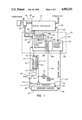
- FIG. 1 is a schematic view of a preferred embodiment of the present invention.
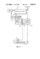
- FIG. 2 is a schematic of an alternate embodiment of the present invention.
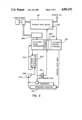
- FIG. 3 is a schematic of another alternate embodiment of the present invention.
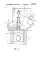
- FIG. 4 is a cross section of an intake valve arrangement for the vapor expander.
- FIG. 1 there is shown an integrated diesel/Rankine cycle system in accordance with a preferred embodiment of the invention for recovering and utilizing energy normally dissipated in the form of heat by operation of a diesel engine.
- the apparatus of the present invention includes an internal combustion engine 50 having a mechanical energy output and a waste heat output.
- the term internal combustion engine as used herein is intended to broadly define an engine wherein combustion takes place, such that the products of combustion, together with any non-reacting substances, perform work by exerting a force on a moving surface, such as a piston, which is coupled to an output component such as a reciprocating rod or rotating shaft from which the work output or mechanical energy output of the engine is available.
- the increase in efficiency obtained with the present invention is particularly significant where the internal combustion engine is a turbocharged diesel engine, however other types of internal combustion engines can be used in accordance herewith.
- the engine is a Cummins L-10 (10 liter, 6 cylinder) diesel engine with a rated output of 250-350 hp.
- the engine is also of the type wherein the waste heat primarily comprises the hot exhaust gases generated during operation of the engine and the heat rejected by the circulating coolant.
- the engine includes an exhaust manifold 26. Hot exhaust gases which are collected in the manifold are routed to a waste heat recovery heat exchanger, or boiler, designated as exhaust stack boiler 31, wherein superheated vapor is generated from a preheated circulating stream of engine cooling fluid. The vapor provides a force to drive a piston disposed within at least one cylinder 35 of the engine, which operates as the expander in the bottoming cycle.
- the fluid source or reservoir 10 is a conventional radiator tank designed for holding an engine cooling fluid and having cooling surfaces.
- the radiator tank may be of conventional construction of suitable metal or other material, having an interior of sufficient size to accommodate an amount of cooling fluid typically used to cool vehicular or stationary diesel engines currently in use in the industry.
- the cooling fluid which also serves as the working fluid for the Rankine cycle, may be selected from known organic Rankine cycle fluids.
- the selected fluid should have good specific heat and other properties which those skilled in the art will recognize as required of an engine coolant.
- Water is a particularly preferred fluid for the integrated system of the present invention.
- other examples include toluene, fluorinol 85, RC-1 (60% penta-fluorobenzene, 40% hexafluoro benzene) and a combination of 50% volume ethylene glycol/50% water.
- the fluid source 10 is connected to a pump 12 through a conventional pipe or conduit 11 which may, for example, comprise metal tubing or conduits which are either flexible or of bendable soft metal, such as copper or aluminum. As described below, the invention contemplates use of conduit means at various points in the fluid flow path which, unless specified otherwise, may similarly be comprised of these materials.
- Conduit 11 leads out of the bottom of fluid source 10 and passes to the intake of pump 12.
- the latter is a conventional water pump capable of delivering the coolant at a predetermined pressure (e.g. 200 psia, absolute pressure).
- a predetermined pressure e.g. 200 psia, absolute pressure
- Other types of pumps typically used in engine cooling systems may also be used in accordance herewith.
- the pump is driven by the engine or by a separate electric motor, not shown. It is preferred that the pump be driven by the engine, as this will reduce complexity of the system and conserve space under the hood in vehicular applications.
- operation of the engine causes pump 12 to pump water from the fluid source 10 via conduit means 13 through an intake orifice 14 on an oil cooler 15, which forms part of the heat transfer means.
- the fluid passes through a passageway or chamber 15a in oil cooler 15.
- the water at intake orifice 14 may have a temperature of approximately 240° F. and a pressure of approximately 95 psia.
- Hot lubricating oil from the engine e.g., 375° F.
- An amount of heat of approximately 2304 Btu/min. may be collected by the flowing water as it passes through oil cooler 15.
- the amount of heat actually collected during passage through the oil cooler, and indeed throughout the remainder of the system will be dependent upon a number of factors, including rated capacity of the engine and the nature of the working fluid selected.
- the present values are not intended to limit the invention in any way but are provided to demonstrate the amount of heat which may be collected at the various points in the fluid flow path in an engine particularly suited for the present system.
- the amount of heat actually collected will also be dependent upon the temperature of the lubricating oil circulating through the chamber. It can thus be appreciated that a lubricant with a higher temperature capability can result in a greater efficiency of the system.
- Slightly heated cooling fluid e.g. water at about 350° F. and at 95 psia
- oil cooler tank 15 passes through an outlet 16 into a conduit means 17.
- T-connector 18 provided in conduit 17, a portion of the water is diverted from the conduit 17 by a booster pump 21 and the remainder of the water continues through main conduit 17 for ultimate recycle through the system.
- T-connector 18 is not essential for the operation of the present invention and accordingly any means by which a portion of the fluid may be diverted from main conduit 17 by booster pump 21 may be used in accordance herewith.
- a thermostat 20 is operatively connected to conduit 17 downstream of the connector 18 and in parallel with booster pump 21.
- a temperature sensing unit of thermostat 20 detects deviation of the temperature of the circulating water from a desired value and transmits the information to a device which controls the flow of cooling fluid through supply conduit means 17a and return conduit means 17b.
- a device which controls the flow of cooling fluid through supply conduit means 17a and return conduit means 17b.
- a pump 21 may be a conventional high pressure positive displacement type capable of delivering the fluid at a predetermined high pressure and extracting at connector 18 approximately 6 lbs/min. of circulating fluid from conduit 17. Particularly preferred for this purpose is a pump 21 capable of delivering the fluid at a pressure of say 800-1000 psia, however, pumps capable of generating pressures of 500 psia may be acceptable for the present invention.
- the pump may be driven directly by the engine or by a separate electric motor, not shown.
- water exiting the booster pump 21 has been pressurized to approximately 1000 psia and has a slightly raised temperature, for example, of 300-400° F. Pressure can be lowered to 500 psia in accordance with the present invention, with only a slight loss in cycle efficiency.
- the fluid which exits booster pump 21 in a pressurized state is delivered to a portion 50a of engine 50 through a conduit 22 and then is circulated through a passageway 23a in a cylinder head 23, and into passageway 26a integral with exhaust manifold 26, both of which also form a portion of the heat transfer means.
- the fluid passes through the cylinder head 23 via a pipe forming a passageway 23a, which is formed from one of a number of metals and cast directly into the cylinder head.
- the pipe may be cast into the cylinder head at the time of manufacture.
- Steel tubing is the preferred material for the pipe forming the fluid passageway 23a through the cylinder head and should have a diameter allowing for a 10 ft/sec.
- the circulating fluid entering at inlet 50a cools the cylinder head 23 and is simultaneously heated to a partially vaporized state.
- the water may collect an amount of heat of approximately 1130 Btu/min. during passage through the cylinder head. It can thus be appreciated that a fairly significant amount of heat energy, which is normally lost to the atmosphere through cooling of the circulating fluid, can be collected by directing the working fluid through the cylinder head 23 in accordance with the present invention.
- the temperature is approximately 550° F.
- the partially vaporized heated fluid passes through conduit means 25 to a passageway 26a, such as a metal chamber, which runs the length of exhaust manifold 26 and which can be molded to the manifold at the time of manufacture.
- the chamber may take the form of a conventional waterjacket or a plurality of cast high pressure steam/water tubes.
- the fluid is further heated as it passes through the metal pipe chamber 26a, which is integral with the exhaust manifold 26.
- Fluid flow through both the cylinder head and exhaust manifold is preferred, although fluid flow through one or the other or both could be eliminated, as this effects the greatest preheating of the fluid from the booster pump 21.
- the partially vaporized, high pressure fluid then passes via a conduit 28 from an exhaust manifold chamber port or outlet 27 to the fluid intake 30 of exhaust stack boiler 31.
- Exhaust stack boiler 31 is a waste heat recovery heat exchanger where superheated vapor at approximately 1000 psia is generated from the energy in the engine exhaust gases.
- Exhaust gases generated during the operation of the engine 50 are passed to the exhaust manifold 26 via a conduit 29 and collected and expanded therein. Typically, these hot exhaust gases are vented to the atmosphere from an exhaust manifold, thereby resulting in a significant loss of heat energy.
- Even in turbocharged systems wherein the expanded exhaust gases are partially harnessed and used to increase the power output of the engine, the exhaust gases exiting the turbocharger are at an elevated temperature. The present invention utilizes this heat energy which it typically lost to the environment to fire the exhaust stack boiler 31.
- Hot exhaust gases exiting the turbocharging unit at outlet 44 are then routed via conduit 45 to an inlet 46 provided on stack boiler 31.
- the exhaust gases collected in exhaust manifold 26 are routed directly to an intake 46 on an exhaust stack boiler 31.
- the exhaust gas flow rate is approximately 50 lb/min. and the exhaust gas inlet temperature to the boiler is approximately 1100° F.
- heat exchangers for diesel engine exhaust gas which may be used in accordance with the present invention are manufactured by Vapor Corporation at 6420 West Howard Street, in Chicago, Ill.
- the size of the heat exchanger will be a function of the fluid inlet temperature to the exhaust stack boiler. The greater the temperature of the preheated fluid entering into the inlet of the exhaust stack boiler, the greater the reduction in size of the exhaust stack boiler which can be achieved.
- Fin spacing in the stack boiler may range from 5-9 fins/inch. It is preferred, however, that the fin spacing be limited to 6 fins/inch in order to avoid potential fouling of the heat transfer surfaces.
- the water collects an additional amount of heat of approximately 5300 Btu/min. as it passes in a heat transfer relation through exhaust stack boiler 31.
- Superheated steam at approximately 1000 psia and approximately 950° F. then exits the exhaust stack boiler 31 at an outlet 32 and flows through a conduit 33 to an intake valve 34 located on expander cylinder 35 of the diesel engine.
- the expander cylinder 12 is the sixth cylinder of the Cummins L-10 engine.
- Other cylinders can be used in accordance with the present invention, however it is preferred that one of the cylinders located at the end of the engine be used, since the cylinder can then easily be isolated from the remaining diesel cylinders.
- the expander cylinder serves as the power recovery device for the bottoming cycle.
- Exhaust gases generated during the exhaust or compression stroke of the piston exit the expander cylinder 35 at an exhaust outlet 36 at approximately 30 psia.
- the exhaust gases which are slightly superheated, pass through a conduit 37 to an inlet 38 located at the top of fluid source 10 and mix with other coolant accumulated therein. The mixing causes the entering exhaust vapor to condense into a partially saturated state which is then available for recycling through the system.
- FIGS. 2 and 3 there are shown two alternate embodiments of the integrated diesel/Rankine system of the present invention.
- a portion of the engine cooling fluid is passed from the fluid source 110 directly to the intake of a high pressure booster pump 121 for immediate entry into the Rankine cycle.
- the elements which have heretofore been shown and described in FIG. 1 are the same as the elements in FIG. 2 in the 100 series.
- oil cooler 15 of FIG. 1 is either bypassed or omitted from the system entirely and accordingly in this embodiment does not form part of the heat transfer means.
- fluid passage through the oil cooler is not necessary to the present invention, but is preferred.
- the result of omitting passage of the working fluid through the oil cooler may be a slight decrease in the temperature of the working fluid at exhaust stack boiler inlet 130.
- the heat transfer means comprises passageway 123a in the cylinder head 123 and the exhaust manifold 126. The remainder of the operation of FIG. 2 is the same as described with reference to FIG. 1.
- FIG. 3 there is shown another alternative embodiment of the integrated diesel/Rankine system according to the present invention, in which the heat transfer means comprises the oil cooler and the cylinder head.
- the heat transfer means comprises the oil cooler and the cylinder head.
- the elements which have hereto been shown and described in FIG. 1 are the same as the elements in FIG. 3, in the 200 series.
- a portion of the working fluid is pumped by a high pressure pump 221 through passageways 223a cast directly into the cylinder head 223 and immediately to an intake 230 of the waste heat recovery heat exchanger, designated as exhaust stack boiler 231 in FIG. 3.
- the working fluid flow path thus bypasses exhaust manifold 226 in this alternative embodiment.
- a system in accordance with this embodiment may thus require a waste heat recovery heat exchanger larger than that required for the preferred embodiment. This is because, as heretofore described, the size of the heat exchanger is directly related to the heat exchanger inlet temperature.
- one of the cylinders of the base diesel engine is used as the power recovery device. It will be appreciated by those skilled in the art that the expander cylinder will produce power every revolution, whereas the remaining cylinders of the engine operate on a four-stroke cycle. Thus, as also will be appreciated by one of ordinary skill in the art, the cam and valve systems for the expander cylinder may be different than for the other five cylinders.
- the intake valve on the expander cylinder should open rapidly to allow all of the working fluid into the cylinder quickly and still have time for the expansion work.
- a rapidly opening valve should provide greater thermal efficiency of the system.
- a sliding valve is preferably used for this purpose, however, those skilled in the art will recognize that other types of valves used in steam reciprocating engines may also be used.
- FIG. 4 there is shown one embodiment of the intake valve arrangement for the vapor expander cylinder, including a sliding valve 70 and an expansion piston 71.
- the expansion piston 71 which is disposed within the cylinder 75 preferably has a flat top portion in order to reduce the dead volume space between the piston 71 and the cylinder head 72. This is in contrast to the remaining diesel pistons, which have combustion chambers at or near the top and accordingly are not very flat.
- the high temperature high pressure vapor is introduced into a vapor intake path 76 in the cylinder head 72.
- expansion piston 71 reaches a point near the top dead center of the cylinder 75 the cam on the cam shaft 73 pushes a follower roller 74 which in turn causes a rocker arm 78 to push the sliding valve 70 in a downward direction.
- An inlet port 81 on the sliding valve 70 is aligned with a port 80 of the steam path.
- the high temperature high pressure vapor then passes through a path 82 in sliding valve 70 into an expansion space 77 between the cylinder head 72 and piston 71, pushing the piston downward.
- the sliding valve 70 closes and the high temperature high pressure vapor expands in the expansion space 77 until the expansion piston 71 reaches a point in the cylinder near the bottom dead center.
- an exhaust valve (not shown in the drawing) opens and exhausts the gases generated during the compression stroke.
- the exhaust valve event can be more gradual, and therefore can be the same as that of the base diesel engine.
- the exhaust valve will not, however, require high temperature alloys, since the temperature of the vapor exiting through the valve is fairly low.
- the same cam that operates the valves and the injectors in the remaining diesel cylinders can be used for the expander cylinder, providing the required valve events are accomplished by modifications such as double-lobed steep ramp cam profile.
- the firing order of a regular 5-cylinder engine may be used for the first five cylinders (1-2-4-5-3-1), with the expander cylinder positioned at a 180 degree crank angle from the No. 1 cylinder.
- This embodiment requires a counter-balancer at the expander cylinder to take the first order unbalance out.
- the crank shaft may be the same as that for a conventional six cylinder engine with an uneven firing order.
- the system of the present invention operates most efficiently when the gases of combustion exiting the engine have sufficient heat content to vaporize the working fluid.
- the waste heat in the exhaust gases is at a relatively low temperature and may be insufficient to generate the high pressure vapor to drive the piston in the expander cylinder.
- the heat being dissipated from the cylinder head and exhaust manifold will be low enough such that a significant preheating of the circulating fluid may not be achieved.
- a control system is provided to control the flow of the circulating fluid into the Rankine cycle at low levels of output.
- Such types of control systems are generally known in the art.
- One type of control system which may be used in accordance with the present invention is disclosed in U.S. Pat. No. 3,979,913. It is envisioned, however, that any number of control systems including various types of temperature-controlled valves, which are normally closed until the engine reaches steam generating temperature, can be used in accordance with the present invention.
Abstract
Description
Claims (1)
Priority Applications (1)
| Application Number | Priority Date | Filing Date | Title |
|---|---|---|---|
| US07/149,850 US4901531A (en) | 1988-01-29 | 1988-01-29 | Rankine-diesel integrated system |
Applications Claiming Priority (1)
| Application Number | Priority Date | Filing Date | Title |
|---|---|---|---|
| US07/149,850 US4901531A (en) | 1988-01-29 | 1988-01-29 | Rankine-diesel integrated system |
Publications (1)
| Publication Number | Publication Date |
|---|---|
| US4901531A true US4901531A (en) | 1990-02-20 |
Family
ID=22532055
Family Applications (1)
| Application Number | Title | Priority Date | Filing Date |
|---|---|---|---|
| US07/149,850 Expired - Lifetime US4901531A (en) | 1988-01-29 | 1988-01-29 | Rankine-diesel integrated system |
Country Status (1)
| Country | Link |
|---|---|
| US (1) | US4901531A (en) |
Cited By (93)
| Publication number | Priority date | Publication date | Assignee | Title |
|---|---|---|---|---|
| EP0434419A2 (en) * | 1989-12-21 | 1991-06-26 | Oy Wärtsilä Diesel International Ltd. | Method and apparatus for effecting heat energy recovery in a large diesel engine |
| EP0592059A1 (en) * | 1992-10-07 | 1994-04-13 | MANNESMANN Aktiengesellschaft | Process and system for compressing a gas |
| US5339632A (en) * | 1992-12-17 | 1994-08-23 | Mccrabb James | Method and apparatus for increasing the efficiency of internal combustion engines |
| WO1995004872A1 (en) * | 1993-08-09 | 1995-02-16 | Livien Domien Ven | Vapor force engine |
| US5609029A (en) * | 1993-07-08 | 1997-03-11 | Wartsila Diesel International Ltd Oy | Thermal power engine and its operating method |
| US5875633A (en) * | 1998-04-24 | 1999-03-02 | Lawson, Jr.; Thomas Towles | Cooling system for internal combustion engines |
| US6216462B1 (en) * | 1999-07-19 | 2001-04-17 | The United States Of America As Represented By The Administrator Of The Environmental Protection Agency | High efficiency, air bottoming engine |
| US6450283B1 (en) | 2000-11-27 | 2002-09-17 | Michael Blake Taggett | Waste heat conversion system |
| US20040088993A1 (en) * | 2002-11-13 | 2004-05-13 | Radcliff Thomas D. | Combined rankine and vapor compression cycles |
| US20040088983A1 (en) * | 2002-11-13 | 2004-05-13 | Carrier Corporation | Dual-use radial turbomachine |
| US20040088986A1 (en) * | 2002-11-13 | 2004-05-13 | Carrier Corporation | Turbine with vaned nozzles |
| US20040255587A1 (en) * | 2003-06-17 | 2004-12-23 | Utc Power, Llc | Organic rankine cycle system for use with a reciprocating engine |
| US20040255593A1 (en) * | 2002-11-13 | 2004-12-23 | Carrier Corporation | Combined rankine and vapor compression cycles |
| US20040255584A1 (en) * | 2001-10-20 | 2004-12-23 | Herbert Clemens | Device for producing mechanical energy |
| US6892522B2 (en) | 2002-11-13 | 2005-05-17 | Carrier Corporation | Combined rankine and vapor compression cycles |
| US20050103465A1 (en) * | 2003-11-18 | 2005-05-19 | Carrier Corporation | Emergency power generation system |
| US20050103016A1 (en) * | 2003-11-18 | 2005-05-19 | Utc Power, Llc | Organic rankine cycle system with shared heat exchanger for use with a reciprocating engine |
| US20050132704A1 (en) * | 2003-12-19 | 2005-06-23 | United Technologies Corporation | Apparatus and method for detecting low charge of working fluid in a waste heat recovery system |
| US20050144949A1 (en) * | 2003-06-23 | 2005-07-07 | Shinichi Hamada | Waste heat recovery system of heat source, with rankine cycle |
| US20050166607A1 (en) * | 2004-02-03 | 2005-08-04 | United Technologies Corporation | Organic rankine cycle fluid |
| US20050171736A1 (en) * | 2004-02-02 | 2005-08-04 | United Technologies Corporation | Health monitoring and diagnostic/prognostic system for an ORC plant |
| EP1593820A1 (en) * | 2004-05-04 | 2005-11-09 | Uwe Hansen | Method for increasing the efficiency of all thermal engines, characterised in that the produced thermal energy is converted in to mechanical energy up to a temperature lower than 100 C. |
| US20050262842A1 (en) * | 2002-10-11 | 2005-12-01 | Claassen Dirk P | Process and device for the recovery of energy |
| US6989989B2 (en) | 2003-06-17 | 2006-01-24 | Utc Power Llc | Power converter cooling |
| US20060053785A1 (en) * | 2003-05-09 | 2006-03-16 | Masayoshi Mori | Power device equipped with combustion engine and stirling engine |
| US20060114994A1 (en) * | 2004-12-01 | 2006-06-01 | Silverstein D Amnon | Noise reduction in a digital video |
| US20060112693A1 (en) * | 2004-11-30 | 2006-06-01 | Sundel Timothy N | Method and apparatus for power generation using waste heat |
| US20060179842A1 (en) * | 2002-11-13 | 2006-08-17 | Carrier Corporation | Power generation with a centrifugal compressor |
| FR2885169A1 (en) * | 2005-04-27 | 2006-11-03 | Renault Sas | Onboard heat energy managing system for vehicle, has Rankine cycle energy recovery circuit comprising bypass control valve in parallel with turbine which provides mechanical energy from fluid at vapor state |
| US20060266030A1 (en) * | 2004-08-10 | 2006-11-30 | Solomon Jason D | Expansion motor |
| WO2006138459A2 (en) * | 2005-06-16 | 2006-12-28 | Utc Power Corporation | Organic rankine cycle mechanically and thermally coupled to an engine driving a common load |
| DE102005048795B3 (en) * | 2005-10-12 | 2006-12-28 | Köhler & Ziegler Anlagentechnik GmbH | Combined heat and power generation plant, has heat exchanger provided next to feed pumps as stage for coupling low temperature heat, and another heat exchanger provided as another stage for coupling high temperature heat |
| US7181913B1 (en) * | 2005-05-06 | 2007-02-27 | Reed Jed A | Steam-generating drive system |
| EP1809865A2 (en) * | 2004-09-14 | 2007-07-25 | Cyclone Technologies LLLP | Heat regenerative engine |
| US7260934B1 (en) * | 2006-04-05 | 2007-08-28 | John Hamlin Roberts | External combustion engine |
| WO2007115579A2 (en) * | 2006-04-12 | 2007-10-18 | Man Diesel A/S | A large turbocharged diesel engine with energy recovery arrangment |
| US20070240420A1 (en) * | 2002-05-22 | 2007-10-18 | Ormat Technologies, Inc. | Integrated engine generator rankine cycle power system |
| EP1870575A2 (en) * | 2006-06-23 | 2007-12-26 | MAN Nutzfahrzeuge Aktiengesellschaft | Charged combustion engine with an expander unit in a heat recovery loop |
| US20080022682A1 (en) * | 2005-11-04 | 2008-01-31 | Tafas Triantafyllos P | Energy recovery system in an engine |
| US20080092539A1 (en) * | 2006-10-23 | 2008-04-24 | Southwest Research Institute | System And Method For Cooling A Combustion Gas Charge |
| WO2008106774A1 (en) * | 2007-03-02 | 2008-09-12 | Victor Juchymenko | Controlled organic rankine cycle system for recovery and conversion of thermal energy |
| US20080289313A1 (en) * | 2005-10-31 | 2008-11-27 | Ormat Technologies Inc. | Direct heating organic rankine cycle |
| US20090000299A1 (en) * | 2007-06-29 | 2009-01-01 | General Electric Company | System and method for recovering waste heat |
| US20090013686A1 (en) * | 2006-02-02 | 2009-01-15 | Hiroshi Yaguchi | Exhaust heat recovery apparatus |
| US20090071155A1 (en) * | 2007-09-14 | 2009-03-19 | General Electric Company | Method and system for thermochemical heat energy storage and recovery |
| US20090235664A1 (en) * | 2008-03-24 | 2009-09-24 | Total Separation Solutions, Llc | Cavitation evaporator system for oil well fluids integrated with a Rankine cycle |
| CN101576023A (en) * | 2008-05-05 | 2009-11-11 | 曼商用车辆奥地利股份公司 | Drive unit and working method thereof |
| US20100026011A1 (en) * | 2006-12-21 | 2010-02-04 | Nederlandse Oraganisatie Voor Toegepastnatuurwetenschappelijk Onderzoek | Expansion Circuit |
| US7665304B2 (en) | 2004-11-30 | 2010-02-23 | Carrier Corporation | Rankine cycle device having multiple turbo-generators |
| US20100064682A1 (en) * | 2008-04-25 | 2010-03-18 | Dean Kamen | Thermal Energy Recovery System |
| US20100083919A1 (en) * | 2008-10-03 | 2010-04-08 | Gm Global Technology Operations, Inc. | Internal Combustion Engine With Integrated Waste Heat Recovery System |
| WO2010054724A2 (en) * | 2008-11-13 | 2010-05-20 | Daimler Ag | Clausius-rankine cycle |
| US20100146949A1 (en) * | 2006-09-25 | 2010-06-17 | The University Of Sussex | Vehicle power supply system |
| US20100146974A1 (en) * | 2008-12-16 | 2010-06-17 | General Electric Company | System for recovering waste heat |
| US7793493B1 (en) * | 2009-12-04 | 2010-09-14 | Robert Mcilroy | Turbocharged internal combustion/steam hybrid engine |
| WO2010102874A2 (en) | 2009-03-10 | 2010-09-16 | Newcomen S.R.L. | Integrated rankine-cycle machine |
| US20100263380A1 (en) * | 2007-10-04 | 2010-10-21 | United Technologies Corporation | Cascaded organic rankine cycle (orc) system using waste heat from a reciprocating engine |
| WO2011006904A2 (en) | 2009-07-14 | 2011-01-20 | Creaidea B.V. | Use of rankine cycle apparatus in vessels |
| US20110061833A1 (en) * | 2008-05-07 | 2011-03-17 | Yanmar Co., Ltd. | Stationary engine coolant circuit |
| US20110072818A1 (en) * | 2009-09-21 | 2011-03-31 | Clean Rolling Power, LLC | Waste heat recovery system |
| WO2011073718A3 (en) * | 2009-12-18 | 2011-11-24 | Renault Trucks | Internal combustion engine arrangement with rankine circuit and hybrid cylinder, especially for an automotive vehicle |
| DE102010056297B3 (en) * | 2010-12-24 | 2011-12-15 | Robert Bosch Gmbh | Waste heat utilization system |
| WO2012013470A1 (en) * | 2010-07-28 | 2012-02-02 | Robert Bosch Gmbh | Piston engine drivable using a steam power process |
| WO2012025775A1 (en) * | 2010-08-27 | 2012-03-01 | Renault Trucks | Engine arrangement comprising a heat recovery circuit |
| EP2466093A1 (en) * | 2010-12-15 | 2012-06-20 | Harald Lück | Power machine with combined combustion and steam operation for generating electricity |
| DE102010056299A1 (en) | 2010-12-24 | 2012-06-28 | Robert Bosch Gmbh | Waste heat utilization system |
| DE102010056272A1 (en) | 2010-12-24 | 2012-06-28 | Robert Bosch Gmbh | Waste heat utilization system |
| DE102010056273A1 (en) | 2010-12-24 | 2012-06-28 | Robert Bosch Gmbh | Waste heat utilization system |
| DE202011101243U1 (en) | 2011-05-30 | 2012-08-31 | Robert Bosch Gmbh | Waste heat utilization system |
| EP2530257A2 (en) | 2011-05-30 | 2012-12-05 | Robert Bosch Gmbh | Waste heat usage assembly |
| US20130186088A1 (en) * | 2012-01-24 | 2013-07-25 | GM Global Technology Operations LLC | Adaptive heat exchange architecture for optimum energy recovery in a waste heat recovery architecture |
| US20130276448A1 (en) * | 2011-10-13 | 2013-10-24 | Laurie Davies | Vaporization Apparatus |
| EP2678548A1 (en) * | 2011-02-25 | 2014-01-01 | Scania CV AB | System for converting thermal energy to mechanical energy in a vehicle |
| US8739531B2 (en) | 2009-01-13 | 2014-06-03 | Avl Powertrain Engineering, Inc. | Hybrid power plant with waste heat recovery system |
| EP2762688A1 (en) * | 2011-09-30 | 2014-08-06 | Nissan Motor Co., Ltd | Rankine cycle system |
| CN103982260A (en) * | 2014-05-30 | 2014-08-13 | 吉林大学 | Single shaft work element organic Rankine cycle low quality energy utilization device |
| US8839620B2 (en) | 2009-01-13 | 2014-09-23 | Avl Powertrain Engineering, Inc. | Sliding vane rotary expander for waste heat recovery system |
| US20140318131A1 (en) * | 2013-04-25 | 2014-10-30 | Herman Artinian | Heat sources for thermal cycles |
| US8919123B2 (en) | 2010-07-14 | 2014-12-30 | Mack Trucks, Inc. | Waste heat recovery system with partial recuperation |
| US9051900B2 (en) | 2009-01-13 | 2015-06-09 | Avl Powertrain Engineering, Inc. | Ejector type EGR mixer |
| US9074492B2 (en) | 2012-04-30 | 2015-07-07 | Electro-Motive Diesel, Inc. | Energy recovery arrangement having multiple heat sources |
| US9181866B2 (en) | 2013-06-21 | 2015-11-10 | Caterpillar Inc. | Energy recovery and cooling system for hybrid machine powertrain |
| US9217388B2 (en) | 2013-01-28 | 2015-12-22 | Jon Mark Larson | Controlled power integrated combustion heat recovery engine |
| WO2017079770A1 (en) | 2015-11-04 | 2017-05-11 | GM Global Technology Operations LLC | Reciprocating expander valve |
| CN107023363A (en) * | 2016-02-02 | 2017-08-08 | 福特环球技术公司 | For energy recovery in cylinder and the system and method for control cylinder temperature |
| US20170356321A1 (en) * | 2016-06-09 | 2017-12-14 | Cummins Inc. | Waste heat recovery architecture for opposed-piston engines |
| DE102016216303A1 (en) | 2016-08-30 | 2018-03-01 | Robert Bosch Gmbh | Waste heat recovery system |
| US10066512B2 (en) * | 2010-07-20 | 2018-09-04 | Mahle International Gmbh | System for using the waste heat of an internal combustion engine |
| DE102017107916A1 (en) * | 2017-04-12 | 2018-10-18 | Dr. Ing. H.C. F. Porsche Aktiengesellschaft | Method for operating an internal combustion engine of a motor vehicle |
| EP2971619B1 (en) * | 2013-03-12 | 2018-10-24 | ELETTROMECCANICA VENETA S.r.l. | Closed-cycle plant |
| US20190056101A1 (en) * | 2011-10-13 | 2019-02-21 | Tinman Inc. | Vaporization Apparatus |
| EP3362711A4 (en) * | 2016-12-23 | 2019-06-26 | GM Global Technology Operations LLC | Reciprocating expander valve |
| US20230250751A1 (en) * | 2020-08-28 | 2023-08-10 | Cae (Ip) Llp | A Mono-Block Reciprocating Piston Composite ICE/ORC Power Plant |
Citations (19)
| Publication number | Priority date | Publication date | Assignee | Title |
|---|---|---|---|---|
| US1011520A (en) * | 1910-11-25 | 1911-12-12 | Harry Benwell Stocks | Combined internal-combustion and fluid-pressure engine. |
| US1339177A (en) * | 1916-03-14 | 1920-05-04 | Leonard H Dyer | Power plant |
| GB400914A (en) * | 1932-01-29 | 1933-11-02 | Selco Motor Company Aktiebolag | Systems for the utilisation of exhaust gas |
| GB581680A (en) * | 1940-05-16 | 1946-10-22 | Richard William Bailey | Improvements in and relating to power plant for the propulsion of ships |
| US3350876A (en) * | 1966-01-19 | 1967-11-07 | Roy W P Johnson | Internal combustion engine plant |
| DE2414147A1 (en) * | 1974-03-23 | 1975-10-09 | Ewald Dipl Ing Renner | Motor vehicle IC engine - has auxiliary cylinder worked by vapourised cooling fluid from main engine |
| US3945210A (en) * | 1974-06-07 | 1976-03-23 | Rodina Energy R & D Corporation | Energy recovery |
| US3979913A (en) * | 1975-01-20 | 1976-09-14 | Yates Harold P | Method and system for utilizing waste energy from internal combustion engines as ancillary power |
| US4031705A (en) * | 1974-11-15 | 1977-06-28 | Berg John W | Auxiliary power system and apparatus |
| US4087974A (en) * | 1976-02-05 | 1978-05-09 | Vaughan Raymond C | Method and apparatus for generating steam |
| US4197712A (en) * | 1978-04-21 | 1980-04-15 | Brigham William D | Fluid pumping and heating system |
| US4201058A (en) * | 1976-02-05 | 1980-05-06 | Vaughan Raymond C | Method and apparatus for generating steam |
| US4235077A (en) * | 1978-10-30 | 1980-11-25 | Bryant Clyde C | Combination engine |
| US4276747A (en) * | 1978-11-30 | 1981-07-07 | Fiat Societa Per Azioni | Heat recovery system |
| US4300353A (en) * | 1975-07-24 | 1981-11-17 | Ridgway Stuart L | Vehicle propulsion system |
| US4334409A (en) * | 1979-02-22 | 1982-06-15 | Societe D'etudes De Machines Thermiques S.E.M.T. | Device for recovering heat energy in a supercharged internal-combustion engine |
| US4348991A (en) * | 1980-10-16 | 1982-09-14 | Cummins Engine Company, Inc. | Dual coolant engine cooling system |
| US4366674A (en) * | 1980-06-06 | 1983-01-04 | Caterpillar Tractor Co. | Internal combustion engine with Rankine bottoming cycle |
| US4586337A (en) * | 1984-01-17 | 1986-05-06 | Cummins Engine Company, Inc. | Turbocompound system |
-
1988
- 1988-01-29 US US07/149,850 patent/US4901531A/en not_active Expired - Lifetime
Patent Citations (19)
| Publication number | Priority date | Publication date | Assignee | Title |
|---|---|---|---|---|
| US1011520A (en) * | 1910-11-25 | 1911-12-12 | Harry Benwell Stocks | Combined internal-combustion and fluid-pressure engine. |
| US1339177A (en) * | 1916-03-14 | 1920-05-04 | Leonard H Dyer | Power plant |
| GB400914A (en) * | 1932-01-29 | 1933-11-02 | Selco Motor Company Aktiebolag | Systems for the utilisation of exhaust gas |
| GB581680A (en) * | 1940-05-16 | 1946-10-22 | Richard William Bailey | Improvements in and relating to power plant for the propulsion of ships |
| US3350876A (en) * | 1966-01-19 | 1967-11-07 | Roy W P Johnson | Internal combustion engine plant |
| DE2414147A1 (en) * | 1974-03-23 | 1975-10-09 | Ewald Dipl Ing Renner | Motor vehicle IC engine - has auxiliary cylinder worked by vapourised cooling fluid from main engine |
| US3945210A (en) * | 1974-06-07 | 1976-03-23 | Rodina Energy R & D Corporation | Energy recovery |
| US4031705A (en) * | 1974-11-15 | 1977-06-28 | Berg John W | Auxiliary power system and apparatus |
| US3979913A (en) * | 1975-01-20 | 1976-09-14 | Yates Harold P | Method and system for utilizing waste energy from internal combustion engines as ancillary power |
| US4300353A (en) * | 1975-07-24 | 1981-11-17 | Ridgway Stuart L | Vehicle propulsion system |
| US4087974A (en) * | 1976-02-05 | 1978-05-09 | Vaughan Raymond C | Method and apparatus for generating steam |
| US4201058A (en) * | 1976-02-05 | 1980-05-06 | Vaughan Raymond C | Method and apparatus for generating steam |
| US4197712A (en) * | 1978-04-21 | 1980-04-15 | Brigham William D | Fluid pumping and heating system |
| US4235077A (en) * | 1978-10-30 | 1980-11-25 | Bryant Clyde C | Combination engine |
| US4276747A (en) * | 1978-11-30 | 1981-07-07 | Fiat Societa Per Azioni | Heat recovery system |
| US4334409A (en) * | 1979-02-22 | 1982-06-15 | Societe D'etudes De Machines Thermiques S.E.M.T. | Device for recovering heat energy in a supercharged internal-combustion engine |
| US4366674A (en) * | 1980-06-06 | 1983-01-04 | Caterpillar Tractor Co. | Internal combustion engine with Rankine bottoming cycle |
| US4348991A (en) * | 1980-10-16 | 1982-09-14 | Cummins Engine Company, Inc. | Dual coolant engine cooling system |
| US4586337A (en) * | 1984-01-17 | 1986-05-06 | Cummins Engine Company, Inc. | Turbocompound system |
Non-Patent Citations (2)
| Title |
|---|
| "Technical and Economic Study of Stirling and Rankine Cycle Bottoming Systems for Heavy Truck Diesel Engines", I. Kubo, NASA CR-180833, Sep. 1987. |
| Technical and Economic Study of Stirling and Rankine Cycle Bottoming Systems for Heavy Truck Diesel Engines , I. Kubo, NASA CR 180833, Sep. 1987. * |
Cited By (164)
| Publication number | Priority date | Publication date | Assignee | Title |
|---|---|---|---|---|
| EP0434419A2 (en) * | 1989-12-21 | 1991-06-26 | Oy Wärtsilä Diesel International Ltd. | Method and apparatus for effecting heat energy recovery in a large diesel engine |
| EP0434419A3 (en) * | 1989-12-21 | 1991-10-02 | Oy Wartsila Diesel International Ltd. | Method and apparatus for effecting heat energy recovery in a large diesel engine |
| US5133298A (en) * | 1989-12-21 | 1992-07-28 | Oy Wartsila Diesel International Ltd. | Method and arrangement for effecting heat energy recovery from the exhaust gases of a diesel engine |
| CN1053258C (en) * | 1992-10-07 | 2000-06-07 | 哈罗德·文策尔 | Method and apparatus for compression of gas medium |
| EP0592059A1 (en) * | 1992-10-07 | 1994-04-13 | MANNESMANN Aktiengesellschaft | Process and system for compressing a gas |
| US5339632A (en) * | 1992-12-17 | 1994-08-23 | Mccrabb James | Method and apparatus for increasing the efficiency of internal combustion engines |
| US5609029A (en) * | 1993-07-08 | 1997-03-11 | Wartsila Diesel International Ltd Oy | Thermal power engine and its operating method |
| WO1995004872A1 (en) * | 1993-08-09 | 1995-02-16 | Livien Domien Ven | Vapor force engine |
| US5724814A (en) * | 1993-08-09 | 1998-03-10 | Ven; Livien D. | Vapor force engine |
| US5875633A (en) * | 1998-04-24 | 1999-03-02 | Lawson, Jr.; Thomas Towles | Cooling system for internal combustion engines |
| US6216462B1 (en) * | 1999-07-19 | 2001-04-17 | The United States Of America As Represented By The Administrator Of The Environmental Protection Agency | High efficiency, air bottoming engine |
| US6415607B1 (en) * | 1999-07-19 | 2002-07-09 | The United States Of America As Represented By The Administrator Of The U.S. Environmental Agency | High efficiency, air bottoming engine |
| US6450283B1 (en) | 2000-11-27 | 2002-09-17 | Michael Blake Taggett | Waste heat conversion system |
| US20040255584A1 (en) * | 2001-10-20 | 2004-12-23 | Herbert Clemens | Device for producing mechanical energy |
| US7104063B2 (en) * | 2001-10-20 | 2006-09-12 | Amovis Gmbh | Device for producing mechanical energy |
| US20070240420A1 (en) * | 2002-05-22 | 2007-10-18 | Ormat Technologies, Inc. | Integrated engine generator rankine cycle power system |
| US8061139B2 (en) * | 2002-05-22 | 2011-11-22 | Ormat Technologies, Inc. | Integrated engine generator rankine cycle power system |
| US20050262842A1 (en) * | 2002-10-11 | 2005-12-01 | Claassen Dirk P | Process and device for the recovery of energy |
| US7735324B2 (en) | 2002-11-13 | 2010-06-15 | Carrier Corporation | Power generation with a centrifugal compressor |
| US6880344B2 (en) | 2002-11-13 | 2005-04-19 | Utc Power, Llc | Combined rankine and vapor compression cycles |
| US6892522B2 (en) | 2002-11-13 | 2005-05-17 | Carrier Corporation | Combined rankine and vapor compression cycles |
| US20040088986A1 (en) * | 2002-11-13 | 2004-05-13 | Carrier Corporation | Turbine with vaned nozzles |
| US20070277527A1 (en) * | 2002-11-13 | 2007-12-06 | Utc Power Corporation | Dual-use radial turbomachine |
| US7281379B2 (en) | 2002-11-13 | 2007-10-16 | Utc Power Corporation | Dual-use radial turbomachine |
| US20040088983A1 (en) * | 2002-11-13 | 2004-05-13 | Carrier Corporation | Dual-use radial turbomachine |
| US7254949B2 (en) | 2002-11-13 | 2007-08-14 | Utc Power Corporation | Turbine with vaned nozzles |
| US20040255593A1 (en) * | 2002-11-13 | 2004-12-23 | Carrier Corporation | Combined rankine and vapor compression cycles |
| US6962056B2 (en) | 2002-11-13 | 2005-11-08 | Carrier Corporation | Combined rankine and vapor compression cycles |
| US20040088993A1 (en) * | 2002-11-13 | 2004-05-13 | Radcliff Thomas D. | Combined rankine and vapor compression cycles |
| US20060179842A1 (en) * | 2002-11-13 | 2006-08-17 | Carrier Corporation | Power generation with a centrifugal compressor |
| US7181912B2 (en) * | 2003-05-09 | 2007-02-27 | Honda Motor Co., Ltd. | Power device equipped with combustion engine and stirling engine |
| US20060053785A1 (en) * | 2003-05-09 | 2006-03-16 | Masayoshi Mori | Power device equipped with combustion engine and stirling engine |
| US20040255587A1 (en) * | 2003-06-17 | 2004-12-23 | Utc Power, Llc | Organic rankine cycle system for use with a reciprocating engine |
| US20060034054A1 (en) * | 2003-06-17 | 2006-02-16 | Utc Power Llc | Power converter cooling |
| US6989989B2 (en) | 2003-06-17 | 2006-01-24 | Utc Power Llc | Power converter cooling |
| US7289325B2 (en) | 2003-06-17 | 2007-10-30 | Utc Power Corporation | Power converter cooling |
| US20050144949A1 (en) * | 2003-06-23 | 2005-07-07 | Shinichi Hamada | Waste heat recovery system of heat source, with rankine cycle |
| US7454910B2 (en) * | 2003-06-23 | 2008-11-25 | Denso Corporation | Waste heat recovery system of heat source, with Rankine cycle |
| US7013644B2 (en) * | 2003-11-18 | 2006-03-21 | Utc Power, Llc | Organic rankine cycle system with shared heat exchanger for use with a reciprocating engine |
| US20050103465A1 (en) * | 2003-11-18 | 2005-05-19 | Carrier Corporation | Emergency power generation system |
| US20050103016A1 (en) * | 2003-11-18 | 2005-05-19 | Utc Power, Llc | Organic rankine cycle system with shared heat exchanger for use with a reciprocating engine |
| US7017357B2 (en) | 2003-11-18 | 2006-03-28 | Carrier Corporation | Emergency power generation system |
| US7036315B2 (en) | 2003-12-19 | 2006-05-02 | United Technologies Corporation | Apparatus and method for detecting low charge of working fluid in a waste heat recovery system |
| US20050132704A1 (en) * | 2003-12-19 | 2005-06-23 | United Technologies Corporation | Apparatus and method for detecting low charge of working fluid in a waste heat recovery system |
| US20050171736A1 (en) * | 2004-02-02 | 2005-08-04 | United Technologies Corporation | Health monitoring and diagnostic/prognostic system for an ORC plant |
| US20050166607A1 (en) * | 2004-02-03 | 2005-08-04 | United Technologies Corporation | Organic rankine cycle fluid |
| US7100380B2 (en) | 2004-02-03 | 2006-09-05 | United Technologies Corporation | Organic rankine cycle fluid |
| WO2005106233A1 (en) * | 2004-05-04 | 2005-11-10 | Neue Energie- Verwertungsgesellschaft Mbh | Method for increasing the efficiency of a four-stroke internal combustion engine and four-stroke internal combustion engine |
| EP1593820A1 (en) * | 2004-05-04 | 2005-11-09 | Uwe Hansen | Method for increasing the efficiency of all thermal engines, characterised in that the produced thermal energy is converted in to mechanical energy up to a temperature lower than 100 C. |
| US20060266030A1 (en) * | 2004-08-10 | 2006-11-30 | Solomon Jason D | Expansion motor |
| JP4880605B2 (en) * | 2004-09-14 | 2012-02-22 | サイクロン パワー テクノロジーズ インコーポレイテッド | Heat generation engine |
| EP1809865A2 (en) * | 2004-09-14 | 2007-07-25 | Cyclone Technologies LLLP | Heat regenerative engine |
| JP2008513648A (en) * | 2004-09-14 | 2008-05-01 | サイクロン テクノロジーズ リミテッド ライアビリティ リミテッド パートナーシップ | Heat generation engine |
| EP1809865A4 (en) * | 2004-09-14 | 2009-07-29 | Cyclone Power Technologies Inc | Heat regenerative engine |
| US20060112693A1 (en) * | 2004-11-30 | 2006-06-01 | Sundel Timothy N | Method and apparatus for power generation using waste heat |
| US7665304B2 (en) | 2004-11-30 | 2010-02-23 | Carrier Corporation | Rankine cycle device having multiple turbo-generators |
| US20060114994A1 (en) * | 2004-12-01 | 2006-06-01 | Silverstein D Amnon | Noise reduction in a digital video |
| FR2885169A1 (en) * | 2005-04-27 | 2006-11-03 | Renault Sas | Onboard heat energy managing system for vehicle, has Rankine cycle energy recovery circuit comprising bypass control valve in parallel with turbine which provides mechanical energy from fluid at vapor state |
| US7181913B1 (en) * | 2005-05-06 | 2007-02-27 | Reed Jed A | Steam-generating drive system |
| WO2006138459A2 (en) * | 2005-06-16 | 2006-12-28 | Utc Power Corporation | Organic rankine cycle mechanically and thermally coupled to an engine driving a common load |
| WO2006138459A3 (en) * | 2005-06-16 | 2007-11-29 | Utc Power Llc | Organic rankine cycle mechanically and thermally coupled to an engine driving a common load |
| EP1816318A1 (en) | 2005-10-12 | 2007-08-08 | Köhler & Ziegler Anlagentechnik GmbH | Cogeneration Plant with an Internal Combustion Engine and an Organic Rankine Cycle (ORC) |
| DE102005048795B3 (en) * | 2005-10-12 | 2006-12-28 | Köhler & Ziegler Anlagentechnik GmbH | Combined heat and power generation plant, has heat exchanger provided next to feed pumps as stage for coupling low temperature heat, and another heat exchanger provided as another stage for coupling high temperature heat |
| US20080289313A1 (en) * | 2005-10-31 | 2008-11-27 | Ormat Technologies Inc. | Direct heating organic rankine cycle |
| US8181463B2 (en) * | 2005-10-31 | 2012-05-22 | Ormat Technologies Inc. | Direct heating organic Rankine cycle |
| US20080022682A1 (en) * | 2005-11-04 | 2008-01-31 | Tafas Triantafyllos P | Energy recovery system in an engine |
| US20080022681A1 (en) * | 2005-11-04 | 2008-01-31 | Tafas Triantafyllos P | Energy recovery system in an engine |
| US8166759B2 (en) * | 2006-02-02 | 2012-05-01 | Toyota Jidosha Kabushiki Kaisha | Exhaust heat recovery apparatus |
| US20090013686A1 (en) * | 2006-02-02 | 2009-01-15 | Hiroshi Yaguchi | Exhaust heat recovery apparatus |
| US7260934B1 (en) * | 2006-04-05 | 2007-08-28 | John Hamlin Roberts | External combustion engine |
| WO2007115579A3 (en) * | 2006-04-12 | 2008-06-26 | Man Diesel As | A large turbocharged diesel engine with energy recovery arrangment |
| WO2007115579A2 (en) * | 2006-04-12 | 2007-10-18 | Man Diesel A/S | A large turbocharged diesel engine with energy recovery arrangment |
| EP1870575A2 (en) * | 2006-06-23 | 2007-12-26 | MAN Nutzfahrzeuge Aktiengesellschaft | Charged combustion engine with an expander unit in a heat recovery loop |
| CN101092915B (en) * | 2006-06-23 | 2013-03-13 | 曼卡车和巴士股份公司 | Charged combustion engine with an expander unit in a heat recovery loop |
| EP1870575A3 (en) * | 2006-06-23 | 2010-11-10 | MAN Nutzfahrzeuge Aktiengesellschaft | Charged combustion engine with an expander unit in a heat recovery loop |
| US20080223040A1 (en) * | 2006-06-23 | 2008-09-18 | Heribert Moller | Supercharged Internal Combustion Engine with an Expander Unit in a Heat Recovery Circuit |
| US7845171B2 (en) * | 2006-06-23 | 2010-12-07 | Man Nutzfahrzeuge Ag | Supercharged internal combustion engine with an expander unit in a heat recovery circuit |
| US20100146949A1 (en) * | 2006-09-25 | 2010-06-17 | The University Of Sussex | Vehicle power supply system |
| US7721543B2 (en) * | 2006-10-23 | 2010-05-25 | Southwest Research Institute | System and method for cooling a combustion gas charge |
| US20080092539A1 (en) * | 2006-10-23 | 2008-04-24 | Southwest Research Institute | System And Method For Cooling A Combustion Gas Charge |
| US20100026011A1 (en) * | 2006-12-21 | 2010-02-04 | Nederlandse Oraganisatie Voor Toegepastnatuurwetenschappelijk Onderzoek | Expansion Circuit |
| US8528333B2 (en) | 2007-03-02 | 2013-09-10 | Victor Juchymenko | Controlled organic rankine cycle system for recovery and conversion of thermal energy |
| US9777602B2 (en) | 2007-03-02 | 2017-10-03 | Victor Juchymenko | Supplementary thermal energy transfer in thermal energy recovery systems |
| US20100018207A1 (en) * | 2007-03-02 | 2010-01-28 | Victor Juchymenko | Controlled Organic Rankine Cycle System for Recovery and Conversion of Thermal Energy |
| US20090320477A1 (en) * | 2007-03-02 | 2009-12-31 | Victor Juchymenko | Supplementary Thermal Energy Transfer in Thermal Energy Recovery Systems |
| US10619520B2 (en) | 2007-03-02 | 2020-04-14 | Victor Juchymenko | Controlled organic Rankine cycle system for recovery and conversion of thermal energy |
| WO2008106774A1 (en) * | 2007-03-02 | 2008-09-12 | Victor Juchymenko | Controlled organic rankine cycle system for recovery and conversion of thermal energy |
| WO2008126089A3 (en) * | 2007-04-17 | 2009-02-05 | Ormat Technologies Inc | Integrated engine generator rankine cycle power system |
| US20090000299A1 (en) * | 2007-06-29 | 2009-01-01 | General Electric Company | System and method for recovering waste heat |
| US8561405B2 (en) * | 2007-06-29 | 2013-10-22 | General Electric Company | System and method for recovering waste heat |
| US20090071155A1 (en) * | 2007-09-14 | 2009-03-19 | General Electric Company | Method and system for thermochemical heat energy storage and recovery |
| WO2009038973A3 (en) * | 2007-09-14 | 2010-08-19 | General Electric Company | Method and system for generating energy |
| WO2009038973A2 (en) * | 2007-09-14 | 2009-03-26 | General Electric Company | Method and system for energy storage and recovery |
| US20090071153A1 (en) * | 2007-09-14 | 2009-03-19 | General Electric Company | Method and system for energy storage and recovery |
| US20100263380A1 (en) * | 2007-10-04 | 2010-10-21 | United Technologies Corporation | Cascaded organic rankine cycle (orc) system using waste heat from a reciprocating engine |
| US20090235664A1 (en) * | 2008-03-24 | 2009-09-24 | Total Separation Solutions, Llc | Cavitation evaporator system for oil well fluids integrated with a Rankine cycle |
| EP2281111A4 (en) * | 2008-04-25 | 2014-01-15 | New Power Concepts Llc | Thermal energy recovery system |
| EP2281111A2 (en) * | 2008-04-25 | 2011-02-09 | New Power Concepts LLC | Thermal energy recovery system |
| US9441575B2 (en) | 2008-04-25 | 2016-09-13 | New Power Concepts Llc | Thermal energy recovery system |
| US20100064682A1 (en) * | 2008-04-25 | 2010-03-18 | Dean Kamen | Thermal Energy Recovery System |
| CN101576023B (en) * | 2008-05-05 | 2013-10-30 | 曼卡车和巴士奥地利股份公司 | Drive unit and working method thereof |
| CN101576023A (en) * | 2008-05-05 | 2009-11-11 | 曼商用车辆奥地利股份公司 | Drive unit and working method thereof |
| US20110061833A1 (en) * | 2008-05-07 | 2011-03-17 | Yanmar Co., Ltd. | Stationary engine coolant circuit |
| US20100083919A1 (en) * | 2008-10-03 | 2010-04-08 | Gm Global Technology Operations, Inc. | Internal Combustion Engine With Integrated Waste Heat Recovery System |
| WO2010054724A2 (en) * | 2008-11-13 | 2010-05-20 | Daimler Ag | Clausius-rankine cycle |
| WO2010054724A3 (en) * | 2008-11-13 | 2011-09-15 | Daimler Ag | Clausius-rankine cycle |
| US20100146974A1 (en) * | 2008-12-16 | 2010-06-17 | General Electric Company | System for recovering waste heat |
| US8739531B2 (en) | 2009-01-13 | 2014-06-03 | Avl Powertrain Engineering, Inc. | Hybrid power plant with waste heat recovery system |
| US9051900B2 (en) | 2009-01-13 | 2015-06-09 | Avl Powertrain Engineering, Inc. | Ejector type EGR mixer |
| US8839620B2 (en) | 2009-01-13 | 2014-09-23 | Avl Powertrain Engineering, Inc. | Sliding vane rotary expander for waste heat recovery system |
| WO2010102874A2 (en) | 2009-03-10 | 2010-09-16 | Newcomen S.R.L. | Integrated rankine-cycle machine |
| WO2011006904A2 (en) | 2009-07-14 | 2011-01-20 | Creaidea B.V. | Use of rankine cycle apparatus in vessels |
| US9243518B2 (en) | 2009-09-21 | 2016-01-26 | Sandra I. Sanchez | Waste heat recovery system |
| US20110072818A1 (en) * | 2009-09-21 | 2011-03-31 | Clean Rolling Power, LLC | Waste heat recovery system |
| US7793493B1 (en) * | 2009-12-04 | 2010-09-14 | Robert Mcilroy | Turbocharged internal combustion/steam hybrid engine |
| WO2011073718A3 (en) * | 2009-12-18 | 2011-11-24 | Renault Trucks | Internal combustion engine arrangement with rankine circuit and hybrid cylinder, especially for an automotive vehicle |
| US8919123B2 (en) | 2010-07-14 | 2014-12-30 | Mack Trucks, Inc. | Waste heat recovery system with partial recuperation |
| US10066512B2 (en) * | 2010-07-20 | 2018-09-04 | Mahle International Gmbh | System for using the waste heat of an internal combustion engine |
| CN103026001A (en) * | 2010-07-28 | 2013-04-03 | 罗伯特·博世有限公司 | Piston engine drivable using a steam power process |
| WO2012013470A1 (en) * | 2010-07-28 | 2012-02-02 | Robert Bosch Gmbh | Piston engine drivable using a steam power process |
| US8720420B2 (en) | 2010-08-27 | 2014-05-13 | Renault Trucks | Engine arrangement comprising a heat recovery circuit |
| WO2012025775A1 (en) * | 2010-08-27 | 2012-03-01 | Renault Trucks | Engine arrangement comprising a heat recovery circuit |
| CN102562360A (en) * | 2010-12-15 | 2012-07-11 | 哈拉尔德·吕克 | Engine with combined combustion and steam operation for current generation |
| US20120152184A1 (en) * | 2010-12-15 | 2012-06-21 | Harald Lueck | Engine with combined combustion and steam operation for current generation |
| EP2466093A1 (en) * | 2010-12-15 | 2012-06-20 | Harald Lück | Power machine with combined combustion and steam operation for generating electricity |
| DE102010056299A1 (en) | 2010-12-24 | 2012-06-28 | Robert Bosch Gmbh | Waste heat utilization system |
| DE102010056297B3 (en) * | 2010-12-24 | 2011-12-15 | Robert Bosch Gmbh | Waste heat utilization system |
| WO2012085104A2 (en) | 2010-12-24 | 2012-06-28 | Robert Bosch Gmbh | Waste heat recovery installation |
| WO2012085093A1 (en) | 2010-12-24 | 2012-06-28 | Robert Bosch Gmbh | Waste heat recovery installation |
| US9088188B2 (en) | 2010-12-24 | 2015-07-21 | Robert Bosch Gmbh | Waste-heat recovery system |
| DE102010056273A1 (en) | 2010-12-24 | 2012-06-28 | Robert Bosch Gmbh | Waste heat utilization system |
| DE102010056272A1 (en) | 2010-12-24 | 2012-06-28 | Robert Bosch Gmbh | Waste heat utilization system |
| EP2678548A1 (en) * | 2011-02-25 | 2014-01-01 | Scania CV AB | System for converting thermal energy to mechanical energy in a vehicle |
| EP2678548A4 (en) * | 2011-02-25 | 2014-10-29 | Scania Cv Ab | System for converting thermal energy to mechanical energy in a vehicle |
| EP2530257A2 (en) | 2011-05-30 | 2012-12-05 | Robert Bosch Gmbh | Waste heat usage assembly |
| DE102011102803A1 (en) | 2011-05-30 | 2012-12-06 | Robert Bosch Gmbh | Waste heat utilization system |
| DE202011101243U1 (en) | 2011-05-30 | 2012-08-31 | Robert Bosch Gmbh | Waste heat utilization system |
| EP2762688A4 (en) * | 2011-09-30 | 2015-03-04 | Nissan Motor | Rankine cycle system |
| EP2762688A1 (en) * | 2011-09-30 | 2014-08-06 | Nissan Motor Co., Ltd | Rankine cycle system |
| US20130276448A1 (en) * | 2011-10-13 | 2013-10-24 | Laurie Davies | Vaporization Apparatus |
| US9945554B2 (en) * | 2011-10-13 | 2018-04-17 | Tinman Inc. | Method of steam generation by spraying water onto a duct within a chamber having divider walls |
| US20190056101A1 (en) * | 2011-10-13 | 2019-02-21 | Tinman Inc. | Vaporization Apparatus |
| US11073278B2 (en) * | 2011-10-13 | 2021-07-27 | Tinman Inc | Vaporization apparatus |
| US20130186088A1 (en) * | 2012-01-24 | 2013-07-25 | GM Global Technology Operations LLC | Adaptive heat exchange architecture for optimum energy recovery in a waste heat recovery architecture |
| US8931275B2 (en) * | 2012-01-24 | 2015-01-13 | GM Global Technology Operations LLC | Adaptive heat exchange architecture for optimum energy recovery in a waste heat recovery architecture |
| US9074492B2 (en) | 2012-04-30 | 2015-07-07 | Electro-Motive Diesel, Inc. | Energy recovery arrangement having multiple heat sources |
| US9217388B2 (en) | 2013-01-28 | 2015-12-22 | Jon Mark Larson | Controlled power integrated combustion heat recovery engine |
| EP2971619B1 (en) * | 2013-03-12 | 2018-10-24 | ELETTROMECCANICA VENETA S.r.l. | Closed-cycle plant |
| US9540961B2 (en) * | 2013-04-25 | 2017-01-10 | Access Energy Llc | Heat sources for thermal cycles |
| US20140318131A1 (en) * | 2013-04-25 | 2014-10-30 | Herman Artinian | Heat sources for thermal cycles |
| US9181866B2 (en) | 2013-06-21 | 2015-11-10 | Caterpillar Inc. | Energy recovery and cooling system for hybrid machine powertrain |
| CN103982260A (en) * | 2014-05-30 | 2014-08-13 | 吉林大学 | Single shaft work element organic Rankine cycle low quality energy utilization device |
| US20180306329A1 (en) * | 2015-11-04 | 2018-10-25 | GM Global Technology Operations LLC | Reciprocating expander valve |
| GB2557560A (en) * | 2015-11-04 | 2018-06-20 | Gm Global Tech Operations Llc | Reciprocating expander valve |
| WO2017079770A1 (en) | 2015-11-04 | 2017-05-11 | GM Global Technology Operations LLC | Reciprocating expander valve |
| US10018145B2 (en) | 2016-02-02 | 2018-07-10 | Ford Global Technologies, Llc | System and method for in-cylinder thermal energy recovery and controlling cylinder temperature |
| CN107023363A (en) * | 2016-02-02 | 2017-08-08 | 福特环球技术公司 | For energy recovery in cylinder and the system and method for control cylinder temperature |
| US20170356321A1 (en) * | 2016-06-09 | 2017-12-14 | Cummins Inc. | Waste heat recovery architecture for opposed-piston engines |
| US10400652B2 (en) * | 2016-06-09 | 2019-09-03 | Cummins Inc. | Waste heat recovery architecture for opposed-piston engines |
| DE102016216303A1 (en) | 2016-08-30 | 2018-03-01 | Robert Bosch Gmbh | Waste heat recovery system |
| EP3362711A4 (en) * | 2016-12-23 | 2019-06-26 | GM Global Technology Operations LLC | Reciprocating expander valve |
| DE102017107916A1 (en) * | 2017-04-12 | 2018-10-18 | Dr. Ing. H.C. F. Porsche Aktiengesellschaft | Method for operating an internal combustion engine of a motor vehicle |
| US20230250751A1 (en) * | 2020-08-28 | 2023-08-10 | Cae (Ip) Llp | A Mono-Block Reciprocating Piston Composite ICE/ORC Power Plant |
| US11920513B2 (en) * | 2020-08-28 | 2024-03-05 | Cae (Ip) Llp | Mono-block reciprocating piston composite ICE/ORC power plant |
Similar Documents
| Publication | Publication Date | Title |
|---|---|---|
| US4901531A (en) | Rankine-diesel integrated system | |
| US4366674A (en) | Internal combustion engine with Rankine bottoming cycle | |
| US6672063B1 (en) | Reciprocating hot air bottom cycle engine | |
| US4334409A (en) | Device for recovering heat energy in a supercharged internal-combustion engine | |
| JP5065421B2 (en) | Internal combustion engine using auxiliary steam power recovered from waste heat | |
| US8061140B2 (en) | High efficiency multicycle internal combustion engine with waste heat recovery | |
| US4182127A (en) | Power recovery and feedback system | |
| EP2379861B1 (en) | Split cycle reciprocating piston engine | |
| US4342200A (en) | Combined engine cooling system and waste-heat driven heat pump | |
| US6415607B1 (en) | High efficiency, air bottoming engine | |
| AU2001242649B2 (en) | An engine | |
| US8109097B2 (en) | High efficiency dual cycle internal combustion engine with steam power recovered from waste heat | |
| EP1702141B1 (en) | Organic rankine cycle system with shared heat exchanger for use with a reciprocating engine | |
| US9074492B2 (en) | Energy recovery arrangement having multiple heat sources | |
| CN1130932A (en) | Vapor force engine | |
| AU2001242649A1 (en) | An engine | |
| US10400652B2 (en) | Waste heat recovery architecture for opposed-piston engines | |
| US4090362A (en) | External combustion power cycle and engine with combustion air preheating | |
| JPH0771242A (en) | Method and equipment for compressing gaseous medium | |
| CN103670670B (en) | Turbocharged two stroke uniflow internal combustion engine with crossheads and turbine | |
| CN111527297B (en) | Device for converting thermal energy from heat lost from an internal combustion engine | |
| US6554585B1 (en) | Power generating assembly capable of dual-functionality | |
| GB2063370A (en) | Power recovery and feedback system | |
| US11035270B2 (en) | Internal combustion engine having an exhaust heat recovery system as well as a method for recovering exhaust heat | |
| JP2003524723A (en) | Lever mechanism motor or pump |
Legal Events
| Date | Code | Title | Description |
|---|---|---|---|
| AS | Assignment |
Owner name: CUMMINS ENGINE COMPANY, INC., CORPORATE OFFICE BUI Free format text: ASSIGNMENT OF ASSIGNORS INTEREST.;ASSIGNORS:KUBO, ISOROKU;GHUMAN, AMARJIT S.;REEL/FRAME:004893/0876 Effective date: 19880411 Owner name: CUMMINS ENGINE COMPANY, INC., INDIANA Free format text: ASSIGNMENT OF ASSIGNORS INTEREST;ASSIGNORS:KUBO, ISOROKU;GHUMAN, AMARJIT S.;REEL/FRAME:004893/0876 Effective date: 19880411 |
|
| STCF | Information on status: patent grant |
Free format text: PATENTED CASE |
|
| FEPP | Fee payment procedure |
Free format text: PAYOR NUMBER ASSIGNED (ORIGINAL EVENT CODE: ASPN); ENTITY STATUS OF PATENT OWNER: LARGE ENTITY |
|
| FPAY | Fee payment |
Year of fee payment: 4 |
|
| FPAY | Fee payment |
Year of fee payment: 8 |
|
| FPAY | Fee payment |
Year of fee payment: 12 |
|
| AS | Assignment |
Owner name: CUMMINS ENGINE IP, INC., MINNESOTA Free format text: ASSIGNMENT OF ASSIGNORS INTEREST;ASSIGNOR:CUMMINGS ENGINE COMPANY, INC.;REEL/FRAME:013868/0374 Effective date: 20001001 |