EP0591678A1 - Process for water-softening and applianeg for carrying out this process - Google Patents
Process for water-softening and applianeg for carrying out this process Download PDFInfo
- Publication number
- EP0591678A1 EP0591678A1 EP93113864A EP93113864A EP0591678A1 EP 0591678 A1 EP0591678 A1 EP 0591678A1 EP 93113864 A EP93113864 A EP 93113864A EP 93113864 A EP93113864 A EP 93113864A EP 0591678 A1 EP0591678 A1 EP 0591678A1
- Authority
- EP
- European Patent Office
- Prior art keywords
- container
- inlet
- fresh water
- resin container
- salt
- Prior art date
- Legal status (The legal status is an assumption and is not a legal conclusion. Google has not performed a legal analysis and makes no representation as to the accuracy of the status listed.)
- Withdrawn
Links
Images


Classifications
-
- A—HUMAN NECESSITIES
- A47—FURNITURE; DOMESTIC ARTICLES OR APPLIANCES; COFFEE MILLS; SPICE MILLS; SUCTION CLEANERS IN GENERAL
- A47L—DOMESTIC WASHING OR CLEANING; SUCTION CLEANERS IN GENERAL
- A47L15/00—Washing or rinsing machines for crockery or tableware
- A47L15/42—Details
- A47L15/4229—Water softening arrangements
-
- B—PERFORMING OPERATIONS; TRANSPORTING
- B01—PHYSICAL OR CHEMICAL PROCESSES OR APPARATUS IN GENERAL
- B01J—CHEMICAL OR PHYSICAL PROCESSES, e.g. CATALYSIS OR COLLOID CHEMISTRY; THEIR RELEVANT APPARATUS
- B01J49/00—Regeneration or reactivation of ion-exchangers; Apparatus therefor
- B01J49/75—Regeneration or reactivation of ion-exchangers; Apparatus therefor of water softeners
Definitions
- the invention relates to a method for the dewaxing of fresh water, in particular for dishwashers, wherein a salt solution removed from a salt container during the regeneration process flows through a resin container filled with regeneration resin, through which the fresh water flows during normal operation, and is then passed into a rinsing container.
- the invention further relates to a device for performing this method.
- Water softening systems based on a cation exchanger must be regenerated after each softening process. This is generally done via a salt reservoir, which is integrated separately or on the ion exchanger and releases a predetermined amount of brine into the softening system. With the integrated design, the resin container is made in connection with the salt storage container. In order to avoid complex valve control, in the known dishwashers which are preferably used in the household, the brine is passed through the ion exchanger in the same direction as the water to be softened. The regeneration therefore takes place in direct current for softening. This means that the brine in the known types is flooded from the bottom in ascending order through the resin.
- the lower layers of the exchanger resin are first loaded with calcium and magnesium ions.
- the loading limit is pushed ever further towards the upper end of the cation exchanger bed.
- slipping through Calcium and magnesium ions form the residual hardness in the soft water. If this residual hardness rises above a specified value, the system must be regenerated.
- the regeneration solution In the known regeneration, in which the resins are salted in the same direction as the fresh water flows through, the regeneration solution first reaches the lower, heavily laden layers. The calcium and magnesium ions exchanged there have to be transported through the less loaded layers.
- the excess of regenerating agent must therefore be very high in order to supply the upper layers with an effective regeneration solution in order to achieve an almost 100% regeneration here too.
- the known types therefore have the disadvantage that an additional amount of salt is required to over-salt the softener, which is necessary anyway, in order to fully and completely regenerate the resin.
- DE-OS 29 47 483 has disclosed a softening device which can be used in particular for dishwashers.
- This device contains a resin container, which is connected to a fresh water connection via a first feed line and to a dishwashing container of the dishwasher via a discharge line.
- a salt container is provided which is connected to a metering chamber for fresh water via a second feed line and to the resin container, ie the ion exchanger, via a brine line.
- This type contains a valve both in the supply line of the salt container and in the brine line. These valves are only opened simultaneously during the regeneration process.
- the water collected in the metering chamber flows into the salt container under the influence of gravity. Brine is displaced from the salt container into the ion exchanger via the brine line.
- the invention has for its object to increase the softening performance while saving salt as an environmentally friendly measure.
- the fresh water flows through the resin container from bottom to top in normal operation and the salt solution flows through the resin container from top to bottom in regeneration mode.
- the effect of gravity can be used to advantage.
- the hard water reaches the bottom area of the resin container (ie the ion exchanger) through a corresponding switching of the multi-way valve, flows through the ion exchanger and, after the hardness has been released, is discharged again via the multi-way valve and from there via the discharge line arranged in the upper end area of the resin container passed into the rinsing container.
- the multi-way valve is de-energized.
- the multi-way valve is activated so that the supply line to the salt container is opened. Depending on the setting, more or less water flows from the associated metering chamber into the salt container and from there as brine via the brine line from above into the ion exchanger.
- the Brine flows through the ion exchanger from top to bottom, whereby the displaced water from the ion exchanger is fed into the dishwasher via an open path of the multi-way valve.
- the multi-way valve is then switched off again and the next softening process can begin.
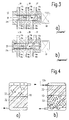
- the multi-way valve is preferably characterized by three inlet and outlet ports, each provided with bores, for connecting the operating lines and by a displaceable valve piston, the valve piston provided with two vertical bores and an oblique bore, which opens or closes different operating paths depending on its position.
- These piston bores are arranged in such a way that the above-mentioned processes can be carried out when the multi-way valve is actuated.
- the operating lines of the salt and resin container with permanently assigned outlet connections of the Multi-way valve connected while the fresh water supply and the connection to the rinsing tank takes place at the mentioned inlet connection.
- the respective operating paths are opened or closed by adjusting the valve piston, the bores of which correspond or not to the bores of the inlet and outlet ports.
- valve piston A single adjustment of the valve piston is sufficient to obtain the switching functions mentioned in a simple and reliable manner.
- a multi-way valve which has three inlet ports 14a, b, c and three outlet ports 15a, b, c.
- the inlet connections are with bores 16a, b, c and the outlet nozzle with holes 17a, b, c (Fig. 3).
- the multi-way valve has a valve piston 19 which is provided with an oblique bore 20 and with two radial bores 21a, b and can be actuated via a magnet 22.
- the multi-way valve 13 assumes the position shown in FIG. 3a.
- the water to be softened passes from a house connection 23 according to arrow 24 via an inlet valve 25, a free flow path 26 to the multi-way valve 13 and from there via the bores 16a, 20, 17a via a feed line 27 into the lower region of the ion exchanger 10.
- Das Hard water 24 flows through the ion exchanger 10 and, after the hardness has been released, is led via the outlet 28 in the upper region of the ion exchanger to the inlet connection 15b of the multi-way valve and from there via the bores 17b, 21a and 16b to the washing container of the dishwasher, not shown.
- the feed line 29 connected to the outlet connection 15c is blocked for the salt container 12.
- the magnet 22 is activated and assumes the position shown in FIG. 3b, in which access to the salt container 12 via the feed line 29 is open.
- more or less water flows from a metering chamber 30 (arrow 30a) into the salt container 12, from there further as brine via the upper brine line 11 with an integrated check valve 31 into the ion exchanger 10.
- the check valve 31 be provided with a brine overflow.
- the upper discharge line 28 is blocked by the valve piston 19 corresponding to 17b, 16b, and the brine 12a flows through the ion exchanger 10 from top to bottom.
- That displaced Water from the ion exchanger 10 is passed via the multi-way valve 13 in accordance with the passage 17a, 20, 16b via the nozzle 14b into the washing container of the dishwasher. After the regeneration process has ended, the multi-way valve 13 is switched off again and the next softening process can take place.
- 4a schematically shows an ion exchanger in a conventional regeneration method in the DC method.
- the flow of the resin arranged in the resin container 10 takes place from bottom to top, both during softening and during regeneration.
- the brine in the resin is denoted by 32 and the distribution of the sodium ions by diffusion is denoted by 33.
- 4b shows the regeneration according to the invention in the countercurrent process.
- the flow of resin through the brine 12a takes place from top to bottom, i.e. in countercurrent to the hard water flow 24.
- the brine in the resin is designated with 32 and with 33 the sodium ion concentration, which was better and faster balanced by diffusion and gravity.
- FIG. 5 schematically shows a water softening device as a monoblock, consisting of a salt container 12, a resin container 10, a multi-way valve 13 and an electromagnet 22, all components being designed as one structural unit.
Abstract
Description
Die Erfindung bezieht sich auf ein Verfahren zur Enthartung von Frischwasser, insbesondere für Geschirrspülmaschinen, wobei eine aus einem Salzbehälter entnommene Salzlösung während des Regeneriervorgangaes einen mit Regenerierharz gefüllten, im Normalbetrieb vom Frischwasser durchflossenen Harzbehälter durchströmt und danach in einen Spülbehälter geleitet wird. Die Erfindung bezieht sich ferner auf eine Einrichtung zur Durchführung dieses Verfahrens.The invention relates to a method for the dewaxing of fresh water, in particular for dishwashers, wherein a salt solution removed from a salt container during the regeneration process flows through a resin container filled with regeneration resin, through which the fresh water flows during normal operation, and is then passed into a rinsing container. The invention further relates to a device for performing this method.
Wasserenthärtungsanlagen auf der Basis eines Kationenaustauschers müssen nach jedem Enthärtungsvorgang wieder regeneriert werden. Dies geschieht im allgemeinen über einen Salzvorratsbehälter, der separat oder am Ionenaustauscher integriert ist und eine vorgegebene Menge Salzsole in das Enthärtungssystem abgibt. Bei der integrierten Bauweise ist der Harzbehälter in Verbindung mit dem Salzvorratsgefäß hergestellt. Um eine aufwendige Ventilsteuerung zu vermeiden, wird bei den bekannten, vorzugsweise im Haushalt verwendeten Geschirrspülern die Salzsole in der gleichen Richtung wie das zu enthärtende Wasser durch den Ionenaustauscher geführt. Die Regeneration findet also im Gleichstrom zur Enthärtung statt. Dies bedeutet, daß die Salzsole bei den bekannten Bauarten von unten aufsteigend durch das Harz geflutet wird. Bei diesem Enthärtungsvorgang des Frischwassers werden zunächst die unteren Schichten des Tauscherharzes mit Calcium- und Magnesiumionen beladen. Während des weiteren Betriebsablaufes schiebt sich die Beladungsgrenze immer weiter gegen das obere Ende des Kationenaustauscherbettes vor. Dann durchschlüpfende Calcium- und Magnesiumionen bilden die Resthärte im Weichwasser. Steigt diese Resthärte über einen spezifizierten Wert an, so muß die Anlage regeneriert werden. Bei der bekannten Regenerierung, bei der die Besalzung der Harze in gleicher Richtung wie das Durchströmen des Frischwassers erfolgt, gelangt die Regenerierlösung zunächst auf die unteren, stark beladenen Schichten. Die dort ausgetauschten Calcium- und Magnesiumionen müssen durch die wenig beladenen Schichten transportiert werden. Der Regeneriermittelüberschuß muß also sehr hoch sein, um auch die oberen Schichten mit wirksamer Regenerierlösung zu versorgen, um auch hier eine fast 100%ige Regeneration zu erreichen. Die bekannten Bauarten haben also den Nachteil, daß zu der sowieso notwendigen Übersalzung des Enthärters eine zusätzliche Menge an Salz benötigt wird, um das Harz allseitig und vollständig zu regenerieren.Water softening systems based on a cation exchanger must be regenerated after each softening process. This is generally done via a salt reservoir, which is integrated separately or on the ion exchanger and releases a predetermined amount of brine into the softening system. With the integrated design, the resin container is made in connection with the salt storage container. In order to avoid complex valve control, in the known dishwashers which are preferably used in the household, the brine is passed through the ion exchanger in the same direction as the water to be softened. The regeneration therefore takes place in direct current for softening. This means that the brine in the known types is flooded from the bottom in ascending order through the resin. In this process of softening the fresh water, the lower layers of the exchanger resin are first loaded with calcium and magnesium ions. During the further course of operation, the loading limit is pushed ever further towards the upper end of the cation exchanger bed. Then slipping through Calcium and magnesium ions form the residual hardness in the soft water. If this residual hardness rises above a specified value, the system must be regenerated. In the known regeneration, in which the resins are salted in the same direction as the fresh water flows through, the regeneration solution first reaches the lower, heavily laden layers. The calcium and magnesium ions exchanged there have to be transported through the less loaded layers. The excess of regenerating agent must therefore be very high in order to supply the upper layers with an effective regeneration solution in order to achieve an almost 100% regeneration here too. The known types therefore have the disadvantage that an additional amount of salt is required to over-salt the softener, which is necessary anyway, in order to fully and completely regenerate the resin.
Durch die DE-OS 29 47 483 ist eine insbesondere für Geschirrspülmaschinen verwendbare Enthärtungseinrichtung bekannt geworden. Diese Einrichtung enthält einen Harzbehälter, der über eine erste Zuleitung mit einem Frischwasseranschluß und über eine Ableitung mit einem Spülbehälter der Geschirrspülmaschine verbunden ist. Ferner ist ein Salzbehälter vorgesehen, der über eine zweite Zuleitung mit einer Dosierkammer für Frischwasser und über eine Soleleitung mit dem Harzbehälter, d.h. dem Ionenaustauscher, verbunden ist. Diese Bauart enthält sowohl in der Zuleitung des Salzbehälters als auch in der Soleleitung je ein Ventil. Diese Ventile werden nur während des Regeneriervorganges gleichzeitig geöffnet. Dabei fließt unter dem Einfluß der Schwerkraft das in der Dosierkammer gesammelte Wasser in den Salzbehälter. Aus dem Salzbehälter wird Sole über die Soleleitung in den Ionenaustauscher verdrängt. Durch die abgestimmte Wassermenge der Dosierkammer wird der Ionenaustauscher völlig mit Sole gefüllt. Nach einer ausreichenden Verweilzeit der Sole im Ionenaustauscher werden die Ventile vor dem Salzbehälter und in der Soleleitung geschlossen, während die Frischwasserzufuhr geöffnet wird. Damit fließt Frischwasser in den Ionenaustauscher und verdrängt die verbrauchte Sole in den Spülbehälter der Geschirrspülmaschine. Bei dieser Bauart treten die oben genannten Nachteile auf.DE-OS 29 47 483 has disclosed a softening device which can be used in particular for dishwashers. This device contains a resin container, which is connected to a fresh water connection via a first feed line and to a dishwashing container of the dishwasher via a discharge line. Furthermore, a salt container is provided which is connected to a metering chamber for fresh water via a second feed line and to the resin container, ie the ion exchanger, via a brine line. This type contains a valve both in the supply line of the salt container and in the brine line. These valves are only opened simultaneously during the regeneration process. The water collected in the metering chamber flows into the salt container under the influence of gravity. Brine is displaced from the salt container into the ion exchanger via the brine line. By the coordinated The amount of water in the dosing chamber is completely filled with brine. After a sufficient dwell time of the brine in the ion exchanger, the valves in front of the salt container and in the brine line are closed while the fresh water supply is opened. Fresh water thus flows into the ion exchanger and displaces the used brine into the dishwasher's rinse tank. The disadvantages mentioned above occur with this type of construction.
Der Erfindung liegt die Aufgabe zugrunde, unter Einsparung von Salz als umweltschonende Maßnahme die Enthärtungsleistung zu erhöhen.The invention has for its object to increase the softening performance while saving salt as an environmentally friendly measure.
Diese Aufgabe wird bei einem Verfahren der eingangs genannten Art dadurch gelöst, daS die Salzlösung den Harzbehälter (Ionenaustauscher) im Gegenstrom zum Frischwasser durchströmt. Bei dieser Gegenstrombesalzung des Kationentauschers kommt die frische Regenerierlösung zuerst mit den oberen Ionenaustauscherschichten im Harzbehälter in Berührung, ehe sie die stark beladenen Schichten nach unten erreicht. Bei gleicher Reinwasserqualität und Kapazität reicht ein erheblich geringerer Regeneriermittelüberschuß vollkommen aus.This object is achieved in a method of the type mentioned at the outset by the salt solution flowing through the resin container (ion exchanger) in countercurrent to the fresh water. With this countercurrent salting of the cation exchanger, the fresh regeneration solution first comes into contact with the upper ion exchange layers in the resin container before it reaches the heavily loaded layers downwards. With the same pure water quality and capacity, a considerably lower excess of regenerant is completely sufficient.
In Ausgestaltung der Erfindung ist vorgesehen, daß bei einer senkrechten Anordnung des Harzbehälters das Frischwasser im Normalbetrieb den Harzbehälter von unten nach oben und die Salzlösung den Harzbehälter im Regenerierbetrieb von oben nach unten durchströmt. Dabei kann die Wirkung der Schwerkraft vorteilhaft ausgenutzt werden.In an embodiment of the invention it is provided that with a vertical arrangement of the resin container, the fresh water flows through the resin container from bottom to top in normal operation and the salt solution flows through the resin container from top to bottom in regeneration mode. The effect of gravity can be used to advantage.
Zur Durchführung des erfindungsgemäßen Verfahrens dient eine Einrichtung, die einerseits einen Harzbehälter aufweist, der über eine erste Zuleitung mit einem Frischwasseranschluß und über eine Ableitung mit einem Spülbehälter verbindbar ist, und die andererseits einen Salzbehälter aufweist, der über eine Soleleitung mit dem Harzbehälter verbunden und über eine zweite Zuleitung mit einer Dosierkammer für Frischwasser verbindbar ist. Gemäß der Erfindung ist vorgesehen, daß die Frischwasser-Zuleitung für den Harzbehälter im unteren Endbereich und die Ableitung und Soleleitung im oberen Endbereich des Harzbehälters angeordnet sind und daß der Anschluß der Zu- und Ableitungen des Salz- und Harzbehälters derart über ein Mehrwegeventil erfolgt,
- daß im Betriebszustand "Enthärten" die Zuleitung des Salzbehälters geschlossen ist und das Frischwasser den Harzbehälter von unten nach oben durchströmt und
- daß im Betriebszustand "Regenerieren" die Zuleitung des Salzbehälters geöffnet ist und die aus der Soleleitung fließende Sole den Harzbehälter von oben nach unten durchströmt.
- that in the operating state "softening" the supply line of the salt container is closed and the fresh water flows through the resin container from bottom to top and
- that in the operating state "regeneration" the supply line of the salt container is open and the brine flowing from the brine line flows through the resin container from top to bottom.
Im Betriebszustand "Enthärten" gelangt das Hartwasser durch eine entsprechende Schaltung des Mehrwegeventils zunächst in den Bodenbereich des Harzbehälters (d.h. des Ionentauschers), durchströmt den Ionentauscher und wird nach der Härteabgabe über die im oberen Endbereich des Harzbehälters angeordnete Ableitung wieder über das Mehrwegeventil und von dort in den Spülbehälter geleitet. In diesem Betriebszustand ist das Mehrwegeventil spannungslos. Für den Betriebszustand "Regenerieren" wird das Mehrwegeventil so aktiviert, daß die Zuleitung zum Salzbehätler geöffnet wird. Dabei fließt aus der zugehörigen Dosierkammer je nach Einstellung mehr oder weniger Wasser in den Salzbehälter und von dort als Sole über die Soleleitung von oben in den Ionentauscher. Die Salzsole durchströmt den Ionentauscher von oben nach unten, dabei wird das verdrängte Wasser aus dem Ionentauscher über einen geöffneten Weg des Mehrwegeventils in den Geschirrspüler geleitet. Nach Beendigung des Regeneriervorganges wird dann das Mehrwegeventil wieder abgeschaltet, und der nächste Enthärtungsvorgang kann beginnen.In the "softening" operating state, the hard water reaches the bottom area of the resin container (ie the ion exchanger) through a corresponding switching of the multi-way valve, flows through the ion exchanger and, after the hardness has been released, is discharged again via the multi-way valve and from there via the discharge line arranged in the upper end area of the resin container passed into the rinsing container. In this operating state, the multi-way valve is de-energized. For the "Regenerate" operating state, the multi-way valve is activated so that the supply line to the salt container is opened. Depending on the setting, more or less water flows from the associated metering chamber into the salt container and from there as brine via the brine line from above into the ion exchanger. The Brine flows through the ion exchanger from top to bottom, whereby the displaced water from the ion exchanger is fed into the dishwasher via an open path of the multi-way valve. After the regeneration process has ended, the multi-way valve is then switched off again and the next softening process can begin.
Vorzugsweise ist das Mehrwegeventil gekennzeichnet durch drei jeweils mit Bohrungen versehene Eingangs- und Ausgangsstutzen zum Anschluß der Betriebsleitungen und durch einen verschiebbaren Ventilkolben, der mit zwei Senkrechtbohrungen und einer Schrägbohrung versehenen Ventilkolben, der je nach seiner Stellung verschiedene Betriebswege öffnet oder schließt. Diese Kolbenbohrungen sind derart angeordnet, daß die oben genannten Vorgänge bei einer Betätitgung des Mehrwegeventils durchführbar sind.The multi-way valve is preferably characterized by three inlet and outlet ports, each provided with bores, for connecting the operating lines and by a displaceable valve piston, the valve piston provided with two vertical bores and an oblique bore, which opens or closes different operating paths depending on its position. These piston bores are arranged in such a way that the above-mentioned processes can be carried out when the multi-way valve is actuated.
Dabei ist in Ausgestaltung der Erfindung vorgesehen,
- a) daß der erste Eingangsstutzen des Mehrwegeventils mit dem Frischwasserzulauf und der gegenüberliegende Ausgangsstutzen mit der Zuleitung des Harzbehälters verbunden ist,
- b) daß der zweite (mittlere) Eingangsstutzen mit dem Spülbehälter und der gegenüberliegende Ausgangsstutzen mit der Ableitung des Harzbehälters verbunden und
- c) daß der dritte Eingangsstutzen mit einem Regenerier-Vorratsbehälter für Frischwasser und der gegenüberliegende Ausgangsstutzen mit der Zuleitung des Salzbehälters verbunden ist.
- a) that the first inlet connection of the multi-way valve is connected to the fresh water inlet and the opposite outlet connection is connected to the inlet of the resin container,
- b) that the second (middle) inlet connector is connected to the rinsing tank and the opposite outlet connector is connected to the derivative of the resin tank and
- c) that the third inlet connection is connected to a regeneration storage container for fresh water and the opposite outlet connection is connected to the supply line of the salt container.
Wie ersichtlich, sind die Betriebsleitungen des Salz- und Harzbehälters mit fest zugeordneten Ausgangsstutzen des Mehrwegeventils verbunden, während die Frischwasserzuführung und die Verbindung zum Spülbehälter an den genannten Eingangsstutzen erfolgt. Die jeweilige Öffnung oder Schließung der entsprechenden Betriebswege erfolgt durch Verstellung des Ventilkolbens, wobei dessen Bohrungen mit den Bohrungen der Ein- und Ausgangsstutzen korrespondiert oder auch nicht.As can be seen, the operating lines of the salt and resin container with permanently assigned outlet connections of the Multi-way valve connected, while the fresh water supply and the connection to the rinsing tank takes place at the mentioned inlet connection. The respective operating paths are opened or closed by adjusting the valve piston, the bores of which correspond or not to the bores of the inlet and outlet ports.
Die Zuordnung der Bohrungen des Ventilkolbens zu den Bohrungen der Ein- und Ausgangsstutzen erfolgt in Ausgestaltung der Erfindung dadurch,
- a) daß in der Betriebsstellung "Enthärten"
- die Bohrungen der ersten Ein- und Ausgangsstutzen durch die Schrägbohrung des Ventilkolbens verbunden sind,
- die Bohrungen der zweiten Ein- und Ausgangsstutzen durch eine Senkrechtbohrung des Ventilkolbens verbunden sind und
- die Bohrungen der dritten Ein- und Ausgangsstutzen durch den Ventilkolben verschlossen sind,
- b) daß in der Betriebsstellung "Regenerieren"
- die Bohrungen des ersten Eingangsstutzens und des zweiten Ausgangsstutzens durch den Ventilkolben gesperrt sind
- die Bohrungen des zweiten Eingangs- und des ersten Ausgangsstutzens durch die Schrägbohrung des Kolbens verbunden sind und
- die Bohrungen des dritten Eingangs- und Ausgangsstutzens durch eine Senkrechtbohrung des Kolbens verbunden sind.
- a) that in the operating position "softening"
- the bores of the first inlet and outlet ports are connected by the oblique bore of the valve piston,
- the bores of the second inlet and outlet ports are connected by a vertical bore of the valve piston and
- the bores of the third inlet and outlet ports are closed by the valve piston,
- b) that in the operating position "regeneration"
- the bores of the first inlet connector and the second outlet connector are blocked by the valve piston
- the bores of the second inlet and the first outlet nozzle are connected by the oblique bore of the piston and
- the bores of the third inlet and outlet nozzle are connected by a vertical bore of the piston are.
Dabei genügt eine einzige Verstellung des Ventilkolbens, um auf einfache und zuverlässige Weise die genannten Schaltfunktionen zu erhalten.A single adjustment of the valve piston is sufficient to obtain the switching functions mentioned in a simple and reliable manner.
In der Zeichnung ist in den Fig. 1 bis 5 ein Ausführungsbeispiel des Gegenstandes gemäß der Erfindung schematisch dargestellt.
- Fig. 1 zeigt eine Enthärtungseinrichtung mit einem Salzbehälter, einem Harzbehälter (Ionentauscher), einem Frischwasseranschluß und mit Anschlußteilen einer nicht näher dargestellten Geschirrspülmaschine,
- Fig. 2 zeigt eine vergrößerte Darstellung der Enthärtungseinrichtung gemäß Fig. 1,
- Fig. 3a, b zeigen in zwei Betriebsstellungen ein in der Enthärtungseinrichtung verwendetes Mehrwegeventil,
- Fig. 4a, b zeigen eine schematische Darstellung des Regenerierens in einem Ionenaustauscherharz beim Stand der Technik und beim Gegenstand gemäß der Erfindung, und
- Fig. 5 zeigt eine als Monoblock ausgebildete Enthärtungseinrichtung.
- 1 shows a softening device with a salt container, a resin container (ion exchanger), a fresh water connection and with connection parts of a dishwasher, not shown,
- FIG. 2 shows an enlarged illustration of the softening device according to FIG. 1,
- 3a, b show in two operating positions a multi-way valve used in the softening device,
- 4a, b show a schematic representation of the regeneration in an ion exchange resin in the prior art and in the article according to the invention, and
- 5 shows a softening device designed as a monoblock.
Die Enthärtungseinrichtung gemäß Fig. 1 und 2 enthält einen Ionenaustauscher 10 (Harzbehälter), der im oberen Bereich über eine Soleleitung 11 mit einem Salzbehälter 12 verbunden ist, der über einen Deckel 18 verschließbar ist. Mit 13 ist ein Mehrwegeventil bezeichnet, das drei Eingangsstutzen 14a, b, c und drei Ausgangsstutzen 15a, b, c besitzt. Die Eingangsstutzen sind mit Bohrungen 16a, b, c und die Ausgangsstutzen mit Bohrungen 17a, b, c versehen (Fig. 3). Das Mehrwegeventil besitzt einen Ventilkolben 19, der mit einer Schrägbohrung 20 und mit zwei Radialbohrungen 21a, b versehen ist und über einen Magneten 22 betätigt werden kann.1 and 2 contains an ion exchanger 10 (resin container) which is connected in the upper region via a
Im Betriebszustand "Enthärten" nimmt das Mehrwegeventil 13 die in Fig. 3a bezeichnete Stellung ein. Dabei gelangt das zu enthärtende Wasser von einem Hausanschluß 23 gemäß Pfeil 24 über ein Zulaufventil 25, eine freie Fließstrecke 26 zu dem Mehrwegeventil 13 und von dort über die Bohrungen 16a, 20, 17a über eine Zuleitung 27 in den unteren Bereich des Ionentauschers 10. Das Hartwasser 24 durchströmt den Ionentauscher 10 und wird nach der Härteabgabe über den im oberen Bereich des Ionentauschers angebrachten Ablauf 28 zu dem Eingangsstutzen 15b des Mehrwegeventils geführt und von dort über die Bohrungen 17b, 21a und 16b zu dem nicht dargestellten Spülbehälter des Geschirrspülers geleitet. In diesem Betriebszustand ist die an den Ausgangsstutzen 15c angeschlossene Zuleitung 29 für den Salzbehälter 12 gesperrt.In the "softening" operating state, the
Im Betriebszustand "Regenerieren" wird der Magnet 22 aktiviert und nimmt die in Fig. 3b gezeichnete Stellung ein, in der der Zugang zum Salzbehälter 12 über die Zuleitung 29 geöffnet ist. Dabei fließt aus einer Dosierkammer 30 (Pfeil 30a) je nach Einstellung mehr oder weniger Wasser in den Salzbehälter 12, von dort weiter als Sole über die obere Soleleitung 11 mit einem integrierten Rückschlagventil 31 in den Ionentauscher 10. Gemäß Fig. 2 kann das Rückschlagventil 31 mit einem Soleüberlauf versehen sein. In diesem Betriebszustand ist die obere Ableitung 28 durch den Ventilkolben 19 entsprechend 17b, 16b gesperrt, und die Salzsole 12a durchströmt den Ionentauscher 10 von oben nach unten. Das verdrängte Wasser aus dem Ionentauscher 10 wird über das Mehrwegeventil 13 entsprechend dem Durchgang 17a, 20, 16b über den Stutzen 14b in den Spülbehälter des Geschirrspülers geleitet. Nach Beendigung des Regeneriervorganges wird das Mehrwegeventil 13 wieder abgeschaltet, und der nächste Enthärtungsvorgang kann erfolgen.In the "Regenerate" operating state, the
Fig. 4a zeigt schematisch einen Ionentauscher bei einem herkömmlichen Verfahren der Regeneration im Gleichstromverfahren. Hierbei erfolgt die Durchströmung des im Harzbehälter 10 angeordneten Harzes von unten nach oben, und zwar sowohl beim Enthärten als auch beim Regenerieren. Mit 32 ist die Salzsole im Harz und mit 33 ist die Verteilung der Natriumionen durch Diffusion bezeichnet. Fig. 4b zeigt die Regeneration gemäß der Erfindung im Gegenstromverfahren. Hierbei erfolgt die Durchströmung des Harzes durch die Salzsole 12a von oben nach unten, d.h. im Gegenstrom zum Hartwasserdurchfluß 24. Mit 32 ist hier wieder die Salzsole im Harz bezeichnet und mit 33 die Natriumionenkonzentration, die durch Diffusion und Schwerkraft besser und schneller ausgeglichen wurde.4a schematically shows an ion exchanger in a conventional regeneration method in the DC method. Here, the flow of the resin arranged in the
Fig. 5 zeigt schematisch eine Wasserenthärtungseinrichtung als Monoblock, bestehend aus einem Salzbehälter 12, einem Harzbehälter 10, einem Mehrwegeventil 13 und einem Elektromagnet 22, wobei alle Bauteile als eine Baueinheit ausgebildet sind.5 schematically shows a water softening device as a monoblock, consisting of a
Claims (7)
Applications Claiming Priority (2)
| Application Number | Priority Date | Filing Date | Title |
|---|---|---|---|
| DE4232009A DE4232009A1 (en) | 1992-09-24 | 1992-09-24 | Process for water softening and device for carrying out the process |
| DE4232009 | 1992-09-24 |
Publications (1)
| Publication Number | Publication Date |
|---|---|
| EP0591678A1 true EP0591678A1 (en) | 1994-04-13 |
Family
ID=6468737
Family Applications (1)
| Application Number | Title | Priority Date | Filing Date |
|---|---|---|---|
| EP93113864A Withdrawn EP0591678A1 (en) | 1992-09-24 | 1993-08-31 | Process for water-softening and applianeg for carrying out this process |
Country Status (2)
| Country | Link |
|---|---|
| EP (1) | EP0591678A1 (en) |
| DE (1) | DE4232009A1 (en) |
Cited By (3)
| Publication number | Priority date | Publication date | Assignee | Title |
|---|---|---|---|---|
| EP1023868A2 (en) * | 1999-01-29 | 2000-08-02 | Premark FEG L.L.C. | Water softener for dishwasher |
| EP2630905A1 (en) * | 2012-01-30 | 2013-08-28 | Samsung Electronics Co., Ltd | Water softening device and dishwasher having the same |
| EP2845839A1 (en) * | 2013-09-10 | 2015-03-11 | Samsung Electronics Co., Ltd | Water softening apparatus |
Families Citing this family (1)
| Publication number | Priority date | Publication date | Assignee | Title |
|---|---|---|---|---|
| DE102017207568B3 (en) | 2017-05-05 | 2018-09-06 | BSH Hausgeräte GmbH | Water softening system and water-conducting household appliance |
Citations (5)
| Publication number | Priority date | Publication date | Assignee | Title |
|---|---|---|---|---|
| US3204767A (en) * | 1964-02-20 | 1965-09-07 | Borochaner Stuart | Automatic washing machines with water-softening means |
| DE3015728A1 (en) * | 1980-04-24 | 1981-10-29 | Licentia Patent-Verwaltungs-Gmbh, 6000 Frankfurt | Backflow preventer valve for domestic water softener - has double acting lands operated by pressure of flowing liquid |
| EP0152154A2 (en) * | 1984-02-16 | 1985-08-21 | Whirlpool International B.V. | Automatic dishwashing machine for domestic use with means for producing an oxidising solution of sodium hypochlorite |
| DE3440964A1 (en) * | 1984-11-09 | 1986-05-15 | Robert Bosch Gmbh, 7000 Stuttgart | Process for regenerating ion-exchange installations and apparatus for carrying out the process |
| DE3631687A1 (en) * | 1986-09-18 | 1988-03-24 | Licentia Gmbh | Apparatus for metering liquids |
-
1992
- 1992-09-24 DE DE4232009A patent/DE4232009A1/en not_active Withdrawn
-
1993
- 1993-08-31 EP EP93113864A patent/EP0591678A1/en not_active Withdrawn
Patent Citations (5)
| Publication number | Priority date | Publication date | Assignee | Title |
|---|---|---|---|---|
| US3204767A (en) * | 1964-02-20 | 1965-09-07 | Borochaner Stuart | Automatic washing machines with water-softening means |
| DE3015728A1 (en) * | 1980-04-24 | 1981-10-29 | Licentia Patent-Verwaltungs-Gmbh, 6000 Frankfurt | Backflow preventer valve for domestic water softener - has double acting lands operated by pressure of flowing liquid |
| EP0152154A2 (en) * | 1984-02-16 | 1985-08-21 | Whirlpool International B.V. | Automatic dishwashing machine for domestic use with means for producing an oxidising solution of sodium hypochlorite |
| DE3440964A1 (en) * | 1984-11-09 | 1986-05-15 | Robert Bosch Gmbh, 7000 Stuttgart | Process for regenerating ion-exchange installations and apparatus for carrying out the process |
| DE3631687A1 (en) * | 1986-09-18 | 1988-03-24 | Licentia Gmbh | Apparatus for metering liquids |
Cited By (5)
| Publication number | Priority date | Publication date | Assignee | Title |
|---|---|---|---|---|
| EP1023868A2 (en) * | 1999-01-29 | 2000-08-02 | Premark FEG L.L.C. | Water softener for dishwasher |
| EP1023868A3 (en) * | 1999-01-29 | 2001-07-11 | Premark FEG L.L.C. | Water softener for dishwasher |
| EP2630905A1 (en) * | 2012-01-30 | 2013-08-28 | Samsung Electronics Co., Ltd | Water softening device and dishwasher having the same |
| EP2845839A1 (en) * | 2013-09-10 | 2015-03-11 | Samsung Electronics Co., Ltd | Water softening apparatus |
| US9861253B2 (en) | 2013-09-10 | 2018-01-09 | Samsung Electronics Co., Ltd. | Water softening apparatus, dishwasher having the same and control method thereof |
Also Published As
| Publication number | Publication date |
|---|---|
| DE4232009A1 (en) | 1994-03-31 |
Similar Documents
| Publication | Publication Date | Title |
|---|---|---|
| DE19512011C2 (en) | Process for preparing soft water in dishwashers or washing machines | |
| DE2043414C2 (en) | Water softener for washing or dishwashing machine - has standard salt regenerating vessel connected by non-return valve to ion exchange vessel near water inlet | |
| DE2501269A1 (en) | DISHWASHER | |
| EP0000942B1 (en) | Water treatment device for a dish washer | |
| DE1941391A1 (en) | Ion exchange process | |
| DE19903635A1 (en) | Small softener for dishwasher | |
| EP0591678A1 (en) | Process for water-softening and applianeg for carrying out this process | |
| DE2834437C2 (en) | Softening device for program-controlled household appliances, in particular for dishwashers and washing machines | |
| DE1517572A1 (en) | Water softening system | |
| DE60129276T2 (en) | water treatment | |
| DE3839203A1 (en) | Programme-controlled domestic washing machine with a water-softening device | |
| DE1517483B2 (en) | DEVICE FOR THE INDEPENDENT REGENERATION OF ION EXCHANGERS IN WATER SOFTENING DEVICES FOR WASHING OR. DISHWASHERS, IN PARTICULAR DISHWASHING MACHINES | |
| DE2652113C2 (en) | ||
| DE4142665C2 (en) | Program-controlled dishwasher or washing machine with integrated raw water treatment device | |
| DE3015728C2 (en) | Water softening device for dishwashers and washing machines | |
| DE3028743C2 (en) | Softener for dishwashers | |
| DE3621928A1 (en) | Water softening apparatus | |
| DE4422143A1 (en) | Water softener operation | |
| DE3144866C1 (en) | Softening device for household appliances, especially for dishwashers | |
| DE3829620A1 (en) | Metering device for liquids | |
| DE2750658A1 (en) | WATER SOFTENING DEVICE FOR HOUSEHOLD APPLIANCES, IN PARTICULAR DISHWASHING MACHINES | |
| DE3819664A1 (en) | Washing machine with an integrated water-softening device | |
| DE2644759A1 (en) | AUTOMATIC WATER SOFTENER | |
| EP0635304B1 (en) | Flashsoftener | |
| DE3625337A1 (en) | Water softening unit |
Legal Events
| Date | Code | Title | Description |
|---|---|---|---|
| PUAI | Public reference made under article 153(3) epc to a published international application that has entered the european phase |
Free format text: ORIGINAL CODE: 0009012 |
|
| AK | Designated contracting states |
Kind code of ref document: A1 Designated state(s): DE FR GB IT SE |
|
| STAA | Information on the status of an ep patent application or granted ep patent |
Free format text: STATUS: THE APPLICATION IS DEEMED TO BE WITHDRAWN |
|
| 18D | Application deemed to be withdrawn |
Effective date: 19941014 |