EP0591418B1 - Verfahren und vorrichtung zur herstellung faseriger zellulosehaltiger strukturen mittels selektiver entwässerung und so hergestellte faserige zellulosehaltige strukturen - Google Patents
Verfahren und vorrichtung zur herstellung faseriger zellulosehaltiger strukturen mittels selektiver entwässerung und so hergestellte faserige zellulosehaltige strukturen Download PDFInfo
- Publication number
- EP0591418B1 EP0591418B1 EP92914690A EP92914690A EP0591418B1 EP 0591418 B1 EP0591418 B1 EP 0591418B1 EP 92914690 A EP92914690 A EP 92914690A EP 92914690 A EP92914690 A EP 92914690A EP 0591418 B1 EP0591418 B1 EP 0591418B1
- Authority
- EP
- European Patent Office
- Prior art keywords
- basis weight
- region
- regions
- protuberances
- fibrous structure
- Prior art date
- Legal status (The legal status is an assumption and is not a legal conclusion. Google has not performed a legal analysis and makes no representation as to the accuracy of the status listed.)
- Expired - Lifetime
Links
Images


Classifications
-
- D—TEXTILES; PAPER
- D21—PAPER-MAKING; PRODUCTION OF CELLULOSE
- D21F—PAPER-MAKING MACHINES; METHODS OF PRODUCING PAPER THEREON
- D21F11/00—Processes for making continuous lengths of paper, or of cardboard, or of wet web for fibre board production, on paper-making machines
- D21F11/006—Making patterned paper
-
- D—TEXTILES; PAPER
- D21—PAPER-MAKING; PRODUCTION OF CELLULOSE
- D21H—PULP COMPOSITIONS; PREPARATION THEREOF NOT COVERED BY SUBCLASSES D21C OR D21D; IMPREGNATING OR COATING OF PAPER; TREATMENT OF FINISHED PAPER NOT COVERED BY CLASS B31 OR SUBCLASS D21G; PAPER NOT OTHERWISE PROVIDED FOR
- D21H27/00—Special paper not otherwise provided for, e.g. made by multi-step processes
- D21H27/02—Patterned paper
-
- Y—GENERAL TAGGING OF NEW TECHNOLOGICAL DEVELOPMENTS; GENERAL TAGGING OF CROSS-SECTIONAL TECHNOLOGIES SPANNING OVER SEVERAL SECTIONS OF THE IPC; TECHNICAL SUBJECTS COVERED BY FORMER USPC CROSS-REFERENCE ART COLLECTIONS [XRACs] AND DIGESTS
- Y10—TECHNICAL SUBJECTS COVERED BY FORMER USPC
- Y10S—TECHNICAL SUBJECTS COVERED BY FORMER USPC CROSS-REFERENCE ART COLLECTIONS [XRACs] AND DIGESTS
- Y10S162/00—Paper making and fiber liberation
- Y10S162/903—Paper forming member, e.g. fourdrinier, sheet forming member
Definitions
- the present invention relates to a method and apparatus for producing a cellulosic fibrous structure having regions of multiple basis weights and, more particularly, having multiple basis weight regions with a high basis weight region comprising an essentially continuous network.
- a cellulosic fibrous structure is typically executed in a paper having three or more regions discriminated from one another by basis weight.
- Cellulosic fibrous structures such as paper, are well-known in the art. Such fibrous structures are in common use today for paper towels, toilet tissue, facial tissue, etc.
- the cellulosic fibrous structure must balance several competing interests.
- the cellulosic fibrous structure must have a sufficient tensile strength to prevent the cellulosic fibrous structure from tearing or shredding during ordinary use or when undue tensile forces are not applied.
- the cellulosic fibrous structure must also be absorbent, so that liquids may be quickly absorbed and fully retained by the cellulosic fibrous structure.
- the cellulosic fibrous structure should also exhibit sufficient softness, so that it is tactilely pleasing and not harsh during use.
- the fibrous structure should exhibit a high degree of opacity, so that it does not appear flimsy or of low quality to the user.
- the cellulosic fibrous structure must be economical, so that it can be manufactured and sold for a profit, and yet is affordable to the consumer.
- Tensile strength is the ability of the fibrous structure to retain its physical integrity during use. Tensile strength is controlled by the weakest link under tension in the cellulosic fibrous structure. The cellulosic fibrous structure will exhibit no greater tensile strength than that of any region in the cellulosic fibrous structure which is undergoing a tensile loading, as the cellulosic fibrous structure will fracture or tear through such weakest region.
- the tensile strength of a cellulosic fibrous structure may be improved by increasing the basis weight of the cellulosic fibrous structure.
- increasing the basis weight requires more cellulosic fibers to be utilized in the manufacture, leading to greater expense and requiring greater utilization of natural resources for the raw materials.
- Absorbency is the property of the cellulosic fibrous structure which allows it to attract and retain contacted liquids. Both the absolute quantity of liquid retained and the rate at which the fibrous structure absorbs contacted liquids must be considered with respect to the desired end use of the cellulosic fibrous structure. Absorbency is influenced by the density of the cellulosic fibrous structure. If the cellulosic fibrous structure is too dense, the interstices between fibers may be too small and the rate of absorption may not be great enough for the intended use. If the interstices are too large, capillary attraction of contacted liquids is minimized and, due to surface tension limitations, liquids will not be retained by the fibrous structure.
- Softness is the ability of a cellulosic fibrous structure to impart a particularly desirable tactile sensation to the user's skin. Softness is influenced by bulk modulus (fiber flexibility, fiber morphology, bond density and unsupported fiber length), surface texture (crepe frequency, size of various regions and smoothness), and the stick-slip surface coefficient of friction. Softness is inversely proportional to the ability of the cellulosic fibrous structure to resist deformation in a direction normal to the plane of the cellulosic fibrous structure.
- Opacity is the property of a cellulosic fibrous structure which prevents or reduces light transmission therethrough. Opacity is directly related to the basis weight, density and uniformity of fiber distribution of the cellulosic fibrous structure. A cellulosic fibrous structure having relatively greater basis weight or uniformity of fiber distribution will also have greater opacity for a given density. Increasing density will increase opacity to a point, beyond which further densification will decrease opacity.
- One compromise between the various aforementioned properties is to provide a cellulosic fibrous structure having mutually discrete zero basis weight apertures amidst an essentially continuous network having a particular basis weight.
- the discrete apertures represent regions of lower basis weight than the essentially continuous network providing for bending perpendicular to the plane of the cellulosic fibrous structure, and hence increase the flexibility of the cellulosic fibrous structure.
- the apertures are circumscribed by the continuous network, which has a desired basis weight and which controls the tensile strength of the fibrous structure.
- Cellulosic structures comprising the features as appear in the pre-characterising part of claim 1 are known from US-A-3,034,180. US-A-3,034,180 issued May 15, 1962 to Greiner et al.
- cellulosic fibrous structures having bilaterally staggered apertures and aligned apertures.
- cellulosic fibrous structures having various shapes of apertures are disclosed in the prior art.
- Greiner et al. discloses square apertures, diamond-shaped apertures, round apertures and cross-shaped apertures.
- apertured cellulosic fibrous structures have several shortcomings.
- the apertures represent transparencies in the cellulosic fibrous structure and may cause the consumer to feel the structure is of lesser quality or strength than desired.
- the apertures are generally too large to absorb and retain any fluids, due to the limited surface tension of fluids typically encountered by the aforementioned tissue and towel products.
- the basis weight of the network around the apertures must be increased so that sufficient tensile strength is obtained.
- nonapertured structures disclosed in these references provide the advantages of slightly increased opacity and the presence of some absorbency in the discrete low basis weight regions, but do not solve the problem that very little tensile load is carried by the discrete nonzero low basis weight regions, thus limiting the overall burst strength of the cellulosic fibrous structure. Also, neither Johnson et al. nor Boulton teach cellulosic fibrous structures having relatively high opacity in the discrete low basis weight regions.
- Cellulosic fibrous structures are usually manufactured by depositing a liquid carrier having cellulosic fibers homogeneously entrained therein onto an apparatus having a fiber retentive liquid pervious forming element.
- the forming element may be generally planar and is typically an endless belt.
- the pattern may comprise protuberances staggered relative to the adjacent protuberances or aligned with the adjacent protuberances. Each protuberance (whether aligned, or staggered) is equally spaced from the adjacent protuberance. Indeed, Heller et al. utilizes a woven Fourdrinier wire for the protuberances.
- the arrangement of equally spaced protuberances represents another shortcoming in the prior art.
- the apparatuses having this arrangement provide substantially uniform and equal flow resistances (and hence drainage and hence deposition of cellulosic fibers) throughout the entire liquid pervious portion of the forming element utilized to make the cellulosic fibrous structure.
- Substantially equal quantities of cellulosic fibers are deposited in the liquid pervious region because equal flow resistances to the drainage of the liquid carrier are present in the spaces between adjacent protuberances.
- fibers will be relatively homogeneously and uniformly deposited, although not necessarily randomly or uniformly aligned, in each region of the apparatus and will form a cellulosic fibrous structure having a like distribution and alignment of fibers.
- the regions of relatively low flow resistance should be continuous so that a continuous high basis weight network of fibers results, and tensile strength is not sacrificed.
- the regions of relatively high flow resistance (which yield relatively low basis weight regions in the cellulosic fibrous structure) may either be discrete or continuous, as desired.
- the forming element is a forming belt having a plurality of regions discriminated from one another by having different flow resistances.
- the liquid carrier drains through the regions of the forming belt according to and inversely proportional to the flow resistance presented thereby. For example, if there are impervious regions, such as protuberances or blockages in the forming belt, no liquid carrier can drain through these regions and hence relatively few or no fibers will be deposited in such regions.
- the flow resistance of the forming belt according to the present invention is thus critical to determining the pattern in which the cellulosic fibers entrained in the liquid carrier will be deposited. Generally, more fibers will be deposited in zones of the forming belt having a relatively lesser flow resistance, because more liquid carrier may drain through such regions. However, it is to be recognized that the flow resistance of a particular region on the forming belt is not constant and will change as a function of time.
- the invention comprises a single lamina cellulosic fibrous structure having at least three regions disposed in a nonrandom repeating pattern.
- the first region is of relatively high basis weight compared to the other two regions and comprises an essentially continuous network which circumscribes the other two regions.
- the second region is of relatively low basis weight compared to the two other regions and is circumscribed by the first region.
- the third region is of intermediate basis weight relative to the two other regions and is juxtaposed with the second region, peripherally bordering it.
- the second region may be substantially contiguous with the third region, more particularly may circumscribe the third region, and may even be circumjacent the third region.
- a plurality of the cellulosic fibers of the second region are substantially radially oriented.
- the cellulosic fibrous structure according to the present invention may be made according to the process of depositing a liquid carrier having cellulosic fibers suspended therein onto a liquid pervious fiber retentive forming element.
- the liquid carrier drains through the forming element in two simultaneous stages, a high flow rate stage and a low flow rate stage, corresponding respectively to the high and low flow rate zones in the forming belt. Both stages decrease in flow rate as a function of time, due to obturation of the zones with cellulosic fibers.
- the stages are discriminated from one another by the initial mass flow rate through the respective zones.
- the cellulosic fibrous structure according to the present invention may be made on an apparatus comprising a liquid pervious fiber retentive forming element.
- the forming element has two zones, a high flow rate zone and a low flow rate zone.
- the belt also has protuberances which are impervious to the flow of liquid carrier therethrough. The protuberances and the two zones are arranged in a pattern corresponding to the basis weights of the regions of the cellulosic fibrous structure to be formed thereon.
- the forming element may have a means for retaining cellulosic fibers in a pattern of three different basis weights.
- the means for retaining cellulosic fibers in a pattern may comprise zones in the forming element having different hydraulic radii.
- the hydraulic radii of the zones may be made different by having a patterned array of upstanding protuberances in the forming element, by each protuberance being equally spaced from the adjacent protuberance and having a liquid pervious orifice therethrough by having protuberances clustered so that some protuberances are equally spaced from the adjacent protuberances and some protuberances are not equally spaced from the adjacent protuberances, or by combinations of the foregoing.
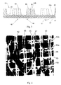
- a cellulosic fibrous structure 20 has three regions: first high basis weight regions 24; second intermediate basis weight regions 26; third low basis weight regions 28.
- Each region 24, 26 or 28 is composed of fibers which are approximated by linear elements.
- the fibers are components of the cellulosic fibrous structure 20 and have one very large dimension (along the longitudinal axis of the fiber) compared to the other two relatively very small dimensions (mutually perpendicular, and being both radial and perpendicular to the longitudinal axis of the fiber), so that linearity is approximated. While microscopic examination of the fibers may reveal two other dimensions which are small, compared to the principal dimension of the fibers, such other two small dimensions need not be substantially equivalent nor constant throughout the axial length of the fiber. It is only important that the fiber be able to bend about its axis, be able to bond to other fibers and be distributed by a liquid carrier.
- the fibers comprising the cellulosic fibrous structure may be synthetic, such as polyolefin or polyester; are preferably cellulosic, such as cotton linters, rayon or bagasse; and more preferably are wood pulp, such as soft woods (gymnosperms or coniferous) or hard woods (angiosperms or deciduous).
- a cellulosic mixture of wood pulp fibers comprising softwood fibers having a length of about 2.0 to about 4.5 millimeters and a diameter of about 25 to about 50 micrometers, and hardwood fibers having a length of less than about 1 millimeter and a diameter of about 12 to about 25 micrometers has been found to work well for the cellulosic fibrous structures 20 described herein.
- the fibers may be produced by any pulping process including chemical processes, such as sulfite, sulphate and soda processes; and mechanical processes such as stone groundwood.
- the fibers may be produced by combinations of chemical and mechanical processes or may be recycled. The type, combination, and processing of the fibers used are not critical to the present invention.
- the various regions 24, 26 and 28 of the cellulosic fibrous structure 20 have the same or a uniform distribution of hardwood and softwood fibers. Instead, it is likely that regions 24, 26 or 28 formed by a zone of the apparatus used to make the cellulosic fibrous structure 20 having a lesser flow resistance will have a greater percentage of softwood fibers. Furthermore, the hardwood and softwood fibers may be layered throughout the thickness of the cellulosic fibrous structure 20.
- a cellulosic fibrous structure 20 according to the present invention is macroscopically two-dimensional and planar, although not necessarily flat.
- the cellulosic fibrous structure 20 may have some thickness in the third dimension.
- the third dimension is very small compared to the actual first two dimensions or to the capability to manufacture a cellulosic fibrous structure 20 having relatively large measurements in the first two dimensions.
- the cellulosic fibrous structure 20 according to the present invention comprises a single lamina. However, it is to be recognized that two or more single laminae, any or all made according to the present invention, may be joined in face-to-face relation to form a unitary laminate.
- a cellulosic fibrous structure 20 according to the present invention is considered to be a "single lamina" if it is taken off the forming element, discussed below, as a single sheet having a thickness prior to drying which does not change unless fibers are added to or removed from the sheet.
- the cellulosic fibrous structure 20 may be later embossed, or remain nonembossed, as desired.
- the cellulosic fibrous structure 20 may be defined by intensive properties which discriminate regions 24, 26 and 28 from each other.
- the basis weight of the fibrous structure 20 is one intensive property which discriminates the regions 24, 26 and 28 from each other.
- a property is considered "intensive” if it does not have a value dependent upon the aggregation of values within the plane of the cellulosic fibrous structure 20.
- intensive properties include the density, projected capillary size, basis weight, temperature, compressive and tensile moduli, etc. of the cellulosic fibrous structure 20.
- properties which depend upon the aggregation of various values of subsystems or components of the cellulosic fibrous structure 20 are considered “extensive.” Examples of extensive properties include the weight, mass, volume, and moles of the cellulosic fibrous structure 20.
- the cellulosic fibrous structure 20 has at least three distinct basis weights which are divided between at least three identifiable areas, referred to as "regions" of the fibrous structure 20.
- the "basis weight” is the weight, measured in grams force, of a unit area of the cellulosic fibrous structure 20, which unit area is taken in the plane of the cellulosic fibrous structure 20.
- the size and shape of the unit area from which the basis weight is measured is dependent upon the relative and absolute sizes and shapes of the regions 24, 26, and 28 having the different basis weights.
- nonrandom repeating pattern corresponds to a nonrandom repeating pattern in the topography of the liquid pervious fiber retentive forming element used to manufacture the cellulosic fibrous structure 20.
- the different basis weights of the regions 24, 26 and 28 provide for different opacities of such regions 24, 26 and 28. While it is desirable from an opacity standpoint to have a uniform basis weight throughout the cellulosic fibrous structure 20, a uniform basis weight cellulosic fibrous structure 20 does not optimize other properties of the cellulosic fibrous structure 20, such as the wet burst strength. However, for the cellulosic fibrous structures 20 described herein, it is to be generally understood that regions 24 of relatively higher basis weight have greater opacity than regions having a lesser basis weight, such as intermediate basis weight regions 26 or low basis weight regions 28.
- the nonrandom repeating pattern tesselates, so that adjacent regions 24, 26 and 28 are cooperatively and advantageously juxtaposed.
- the intensively defined regions 24, 26, and 28 are considered to be predictable, and may occur as a result of known and predetermined features of the apparatus used in the manufacturing process.
- the pattern is formed more than once in the fibrous structure 20.
- the intensively discriminated regions 24, 26, and 28 of the fibrous structure 20 may be "discrete,” so that adjacent regions 24, 26 or 28 having the same basis weight are not contiguous.
- a region 24, 26 or 28 having one basis weight throughout the entirety of the fibrous structure 20 may be "essentially continuous,” so that such region 24, 26 or 28 extends substantially throughout the fibrous structure 20 in one or both of its principal dimensions.
- transition regions having a basis weight intermediate the basis weights of the adjacent regions 24, 26, or 28, which transition regions by themselves may not be significant enough in area to be considered as comprising a basis weight distinct from the basis weights of either adjacent region 24, 26, or 28.
- Such transition regions are within the normal manufacturing variations known and inherent in producing a fibrous structure 20 according to the present invention.
- the size of the pattern of the fibrous structure 20 may vary from about 1.5 to about 390 discrete regions 26 per square centimeter (from 10 to 2,500 discrete regions 26 per square inch), preferably from about 11.6 to about 155 discrete regions 26 per square centimeter (from 75 to 1,000 discrete regions 26 per square inch), and more preferably from about 23.3 to about 85.3 discrete regions 26 per square centimeter (from 150 to 550 discrete regions 26 per square inch).
- the high basis weight region 24 of the fibrous structure 20 is preferably essentially continuous in two orthogonal directions within the plane of the fibrous structure 20. It is not necessary that such orthogonal directions be parallel and perpendicular the edges of the finished product or be parallel and perpendicular the direction of manufacture of the product, but only that tensile strength be imparted to the cellulosic fibrous structure in two orthogonal directions, so that any applied tensile loading may be more readily accommodated without premature failure of the product due to such tensile loading.
- the continuous direction is parallel the direction of expected tensile loading of the finished product according to the present invention.
- the cellulosic fibrous structure 20 comprises three regions, first high basis weight regions 24, second intermediate basis weight regions 26, and third low basis weight regions 28, as noted above.
- the regions 24, 26 and 28 are disposed in a nonrandom repeating pattern described more particularly as follows.
- An example of an essentially continuous network is the high basis weight region 24 of the cellulosic fibrous structure 20 of Figure 1.
- Other examples of cellulosic fibrous structures having essentially continuous networks are disclosed in U.S. Patent 4,637,859 issued January 20, 1987 to Trokhan and incorporated herein by reference for the purpose of showing another cellulosic fibrous structure having an essentially continuous network. Interruptions in the essentially continuous network are tolerable, albeit not preferred, so long as such interruptions do not substantially adversely affect the material properties of such portion of the cellulosic fibrous structure 20.
- the low and intermediate basis weight regions 26 and 28 may be discrete and dispersed throughout the high basis weight essentially continuous network 24.
- the low and intermediate basis weight regions 26 may be thought of as islands which are surrounded by a circumjacent essentially continuous network high basis weight region 24.
- the discrete low basis weight regions 28 and the discrete intermediate basis weight regions 26 also form a nonrandom, repeating pattern.
- the discrete low basis weight regions 28 and the discrete intermediate basis weight regions 26 may be staggered in, or may be aligned in, either or both of the aforementioned two orthogonal directions.
- the high basis weight essentially continuous network 24 forms a patterned network circumjacent the discrete low basis weight regions 28, although, as noted above, small transition regions may be accommodated.
- the high basis weight regions 24 are adjacent, contiguous and circumscribe the low and intermediate basis weight regions 26 and 28.
- the intermediate basis weight regions 26 are juxtaposed with the low basis weight regions 28.
- the low basis weight regions 28 may peripherally border, but not fully circumscribe the intermediate basis weight region 26 or the low basis weight regions 28 may circumscribe the intermediate basis weight regions 26.
- the intermediate basis weight regions 26 are generally smaller in diametrical dimension, although not necessarily in surface area, than the circumjacent low basis weight regions 28.
- the low basis weight regions 28 may further be contiguous and even circumjacent the intermediate basis weight regions 26.
- the relative disposition of the low and intermediate basis weight regions 26 within the high basis weight regions 24 depends upon the disposition of the high and low flow flow rate stage zones zones of different flow resistances in the forming belt 42.
- the fibers of the three regions 24, 26 and 28 may be advantageously aligned in different directions.
- the fibers comprising the essentially continuous high basis weight region 24 may be preferentially aligned in a generally singular direction, corresponding to the essentially continuous network of the annuluses 65 between adjacent protuberances 59 and the influence of the machine direction of the manufacturing process.
- This alignment provides for fibers to be generally mutually parallel, have a relatively high degree of bonding.
- the relatively high degree of bonding produces a relatively high tensile strength in the high basis weight region 24.
- Such high tensile strength in the relatively high basis weight region 24 is generally advantageous, because the high basis weight region 24 carries and transmits applied tensile loading throughout the cellulosic fiber structure 20.
- the relatively low basis weight region 28 comprises fibers, a plurality of which are generally radially oriented, and emanate outwardly from the center of the low basis weight region 28. If the low basis weight region 28 is circumjacent the intermediate basis weight region 26, the fibers of the low basis weight region will also be radially outwardly oriented with respect to the center of the intermediate basis weight region 26. Further, as illustrated in Figure 1, the low basis weight region 28 and the intermediate basis weight region 26 may be and preferably are mutually concentric.
- the apparatus may comprise a means 44 for depositing a liquid carrier and cellulosic fibers entrained therein onto a liquid pervious fiber retentive forming element.
- the liquid pervious fiber retentive forming element may be a forming belt 42, is the heart of the apparatus and represents one component of the apparatus which departs from the prior art to manufacture the cellulosic fibrous structures 20 described and claimed herein.
- the liquid pervious fiber retentive forming element has protuberances 59 which form the low and intermediate basis weight regions 26 of the fibrous structure 20, and intermediate annuluses 65 which form the high basis weight regions 24 of the cellulosic fibrous structure 20.
- the apparatus may further comprise a secondary belt 46 to which the fibrous structure 20 is transferred after the majority of the liquid carrier is drained away and the cellulosic fibers are retained on the forming belt 42.
- the secondary belt 46 may further comprise a pattern of knuckles or projections not coincident the regions 24, 26, and 28 of the cellulosic fibrous structure 20.
- the forming and secondary belts 42 and 46 travel in the directions depicted by arrows A and B respectively.
- the fibrous structure 20 is dried according to either or both of known drying means 50a and 50b, such as a blow through dryer 50a, and/or a Yankee drying drum 50b.
- the apparatus may comprise a means, such as a doctor blade 68, for foreshortening or creping the fibrous structure 20.
- a forming belt 42 is selected for the forming element of the apparatus used to make the cellulosic fibrous structure 20, the forming belt 42 has two mutually opposed faces, a first face 53 and a second face 55, as illustrated in Figure 3.
- the first face 53 is the surface of the forming belt 42 which contacts the fibers of the cellulosic structure 20 being formed.
- the first face 53 has been referred to in the art as the paper contacting side of the forming belt 42.
- the first face 53 has two topographically distinct regions 53a and 53b.
- the regions 53a and 53b are distinguished by the amount of orthogonal variation from the second and opposite face 55 of the forming belt 42. Such orthogonal variation is considered to be in the Z-direction.
- the "Z-direction" refers to the direction away from and generally orthogonal to the XY plane of the forming belt 42, considering the forming belt 42 to be a planar, two-dimensional structure.
- the forming belt 42 should be able to withstand all of the known stresses and operating conditions in which cellulosic, two-dimensional structures are processed and manufactured.
- a particularly preferred forming belt 42 may be made according to the teachings of U.S. Patent 4,514,345 issued April 30, 1985 to Johnson et al., and particularly according Figure 5 of Johnson et al., which patent is incorporated herein by reference for the purpose of showing a particularly suitable forming element for use with the present invention and a method of making such forming element.
- the forming belt 42 is liquid pervious in at least one direction, particularly the direction from the first face 53 of the belt, through the forming belt 42, to the second face 55 of the forming belt 42.
- liquid pervious refers to the condition where the liquid carrier of a fibrous slurry may be transmitted through the forming belt 42 without significant obstruction. It may, of course, be helpful or even necessary to apply a slight differential pressure to assist in transmission of the liquid through the forming belt 42 to insure that the forming belt 42 has the proper degree of perviousness.
- the entire surface area of the forming belt 42 be liquid pervious. It is only necessary that the liquid carrier of the fibrous slurry be easily removed from the slurry leaving on the first face 53 of the forming belt 42 an embryonic fibrous structure 20 of the deposited fibers.
- the forming belt 42 is also fiber retentive.
- a component is considered “fiber retentive” if such component retains a majority of the fibers deposited thereon in a macroscopically predetermined pattern or geometry, without regard to the orientation or disposition of any particular fiber.
- a fiber retentive component will retain one hundred percent of the fibers deposited thereon (particularly as the liquid carrier of the fibers drains away from such component) nor that such retention be permanent. It is only necessary that the fibers be retained on the forming belt 42, or other fiber retentive component, for a period of time sufficient to allow the steps of the process to be satisfactorily completed.
- the forming belt 42 may be thought of as having a reinforcing structure 57 and a patterned array of protuberances 59 joined in face to face relation to the reinforcing structure 57, to define the two mutually opposed faces 53 and 55.
- the reinforcing structure 57 may comprise a foraminous element, such as a woven screen or other apertured framework.
- the reinforcing structure 57 is substantially liquid pervious.
- a suitable foraminous reinforcing structure 57 is a screen having a mesh size of about 6 to about 50 filaments per centimeter (15.2 to 127 filaments per inch) as seen in the plan view, although it is to be recognized that warp filaments are often stacked, doubling the filament count specified above.
- the openings between the filaments may be generally square, as illustrated, or of any other desired cross-section.
- the filaments may be formed of polyester strands, woven or nonwoven fabrics. Particularly, a 52 dual mesh reinforcing structure 57 has been found to work well.
- One face 55 of the reinforcing structure 57 may be essentially macroscopically monoplanar and comprises the outwardly oriented face 53 of the forming belt 42.
- the inwardly oriented face of the forming belt 42 is often referred to as the backside of the forming belt 42 and, as noted above, contacts at least part of the balance of the apparatus employed in a papermaking operation.
- the opposing and outwardly oriented face 53 of the reinforcing structure 57 may be referred to as the fiber-contacting side of the forming belt 42, because the fibrous slurry, discussed above, is deposited onto this face 53 of the forming belt 42.
- the patterned array of protuberances 59 is joined to the reinforcing structure 57 and preferably comprises individual protuberances 59 joined to and extending outwardly from the inwardly oriented face 53 of the reinforcing structure 57 as illustrated in Figure 3.
- the protuberances 59 are also considered to be fiber contacting, because the patterned array of protuberances 59 receives, and indeed may be covered by, the fibrous slurry as it is deposited onto the forming belt 42.
- the protuberances 59 may be joined to the reinforcing structure 57 in any known manner, with a particularly preferred manner being joining a plurality of the protuberances 59 to the reinforcing structure 57 as a batch process incorporating a hardenable polymeric photosensitive resin - rather than individually joining each protuberance 59 of the patterned array of protuberances 59 to the reinforcing structure 57.
- the patterned array of protuberances 59 is preferably formed by manipulating a mass of generally liquid material so that, when solidified, such material is contiguous with and forms part of the protuberances 59 and at least partially surrounds the reinforcing structure 57 in contacting relationship, as illustrated in Figure 3.
- the patterned array of protuberances 59 should be arranged so that a plurality of conduits, into which fibers of the fibrous slurry may deflect, extend in the Z-direction from the free ends 53b of the protuberances 59 to the proximal elevation 53a of the outwardly oriented face 53 of the reinforcing structure 57.
- This arrangement provides a defined topography to the forming belt 42 and allows for the liquid carrier and fibers therein to flow to the reinforcing structure 57.
- the conduits between adjacent protuberances 59 have a defined flow resistance which is dependent upon the pattern, size and spacing of the protuberances 59.
- the protuberances 59 are discrete and preferably regularly spaced so that large scale weak spots in the essentially continuous network 24 of the fibrous structure 20 are not formed.
- the liquid carrier may drain the through annuluses 65 between adjacent protuberances 59 to the reinforcing structure 57 and deposit fibers thereon.
- the protuberances 59 are distributed in a nonrandom repeating pattern so that the essentially continuous network 24 of the fibrous structure 20 (which is formed around and between the protuberances 59) more uniformly distributes applied tensile loading throughout the fibrous structure 20.
- the protuberances 59 are bilaterally staggered in an array, so that adjacent low basis weight regions 28 in the resulting fibrous structure 20 are not aligned with either principal direction to which tensile loading may be applied.
- the protuberances 59 are upstanding and joined at their proximal ends 53a to the outwardly oriented face 53 of the reinforcing structure 57 and extend away from this face 53 to a distal or free end 53b which defines the furthest orthogonal variation of the patterned array of protuberances 59 from the outwardly oriented face 53 of the reinforcing structure 57.
- the outwardly oriented face 53 of the forming belt 42 is defined at two elevations.
- the proximal elevation of the outwardly oriented face 53 is defined by the surface of the reinforcing structure 57 to which the proximal ends 53a of the protuberances 59 are joined, taking into account, of course, any material of the protuberances 59 which surrounds the reinforcing structure 57 upon solidification.
- the distal elevation of the outwardly oriented face 53 is defined by the free ends 53b of the patterned array of protuberances 59.
- the opposed and inwardly oriented face 55 of the forming belt 42 is defined by the other face of the reinforcing structure 57, taking into account, of course, any material of the protuberances 59 which surrounds the reinforcing structure 57 upon solidification, which face is opposite the direction of extent of the protuberances 59.
- the protuberances 59 may extend, orthogonal the plane of the forming belt 42, outwardly from the proximal elevation of the outwardly oriented face 53 of the reinforcing structure 57 about 0 millimeters to about 1.3 millimeters (0 to 0.050 inches). Obviously, if the protuberances 59 have zero extent in the Z-direction, a more nearly constant basis weight cellulosic fibrous structure 20 is approximated. Therefore, if it is desired to minimize the difference in basis weights between adjacent high basis weight regions 24 and low basis weight regions 28 of the cellulosic fibrous structure 20, generally shorter protuberances 59 should be utilized.
- the protuberances 59 preferably do not have sharp corners, particularly in the XY plane, so that stress concentrations in the resulting high basis weight regions 24 of the cellulosic fibrous structure 20 of Figure 1 are obviated.
- a particularly preferred protuberance 59 is curvirhombohedrally shaped, having a cross-section which resembles a rhombus with radiused corners.
- the sides of the protuberances 59 may be generally mutually parallel and orthogonal the plane of the forming belt 42.
- the protuberances 59 may be somewhat tapered, yielding a frustroconical shape, as illustrated in Figure 3.
- protuberances 59 be of uniform height or that the free ends 53b of the protuberances 59 be equally spaced from the proximal elevation 53a of the outwardly oriented face 53 of the reinforcing structure 57. If it is desired to incorporate more complex patterns than those illustrated into the fibrous structure 20, it will be understood by one skilled in the art that this may be accomplished by having a topography defined by several Z-directional levels of upstanding protuberances 59 - each level yielding a different basis weight than occurs in the regions of the fibrous structure 20 defined by the protuberances 59 of the other levels.
- this may be otherwise accomplished by a forming belt 42 having an outwardly oriented face 53 defined by more than two elevations by some other means, for example, having uniform sized protuberances 59 joined to a reinforcing structure 57 having a planarity which significantly varies relative to the Z-direction extent of the protuberances 59.
- the patterned array of protuberances 59 may, preferably, range in area, as a percentage of the projected surface area of the forming belt 42, from a minimum of about 20 percent of the total projected surface area of the forming belt 42 to a maximum of about 80 percent of the total projected surface area of the forming belt 42, with the reinforcing structure 57 providing the balance of the projected surface area of the forming belt 42.
- the contribution of the patterned array of protuberances 59 to the total projected surface area of the forming belt 42 is taken as the aggregate of the projected area of each protuberance 59 taken at the maximum projection against an orthogonal to the outwardly oriented face 53 of the reinforcing structure 57.
- the surface area between adjacent protuberances 59 of the proximal elevation 53a of the forming belt 42 should be increased as the length of the fibers increases, otherwise the fibers may not cover the protuberances 59 and not penetrate the conduits between adjacent protuberances 59 to the reinforcing structure 57 defined by the surface area of the proximal elevation 53a.
- the second face 55 of the forming belt 42 may have a defined and noticeable topography or may be essentially macroscopically monoplanar.
- "essentially macroscopically monoplanar” refers to the geometry of the forming belt 42 when it is placed in a two-dimensional configuration and has only minor and tolerable deviations from absolute planarity, which deviations do not adversely affect the performance of the forming belt 42 in producing cellulosic fibrous structures 20 as described above and claimed below.
- Either geometry of the second face 55, topographical or essentially macroscopically monoplanar, is acceptable, so long as the topography of the first face 53 of the forming belt 42 is not interrupted by deviations of larger magnitude, and the forming belt 42 can be used with the process steps described herein.
- the second face 55 of the forming belt 42 may contact the equipment used in the process of making the fibrous structure 20 and has been referred to in the art as the machine side of the forming belt 42.
- the protuberances 59 define annuluses 65 having multiple and mutually different flow resistances in the liquid pervious portion of the forming belt 42.
- One manner in which differing regions may be provided is illustrated in Figure 4.
- Each protuberance 59 of the forming belt of Figure 4 is substantially equally spaced from the adjacent protuberance 59, providing an essentially continuous network annulus 65 between adjacent protuberances 59.
- the flow resistance of the orifice 63 through the protuberance 59 is different from, and typically greater than, the flow resistance of the annulus 65 between adjacent protuberances 59. Therefore, typically more of the liquid carrier will drain through the annuluses 65 between adjacent protuberances 59 than through the aperture within and circumscribed by the free end 53b of a particular protuberance 59. Because less liquid carrier drains through the orifice 63, than through the annulus 65 between adjacent protuberances 59, relatively more fibers are deposited onto the reinforcing structure 57 subjacent the annulus 65 between adjacent protuberances 59 than onto the reinforcing structure 57 subjacent the apertures 63.
- the annuluses 65 and apertures 63 respectively define high flow rate and and low flow rate zones in the forming belt 42. Because the flow rate through the annuluses 65 is greater than the flow rate through the apertures 63 (due to the greater flow resistance of the apertures 63) the initial mass flow rate of the liquid carrier will be greater through the annuluses 65 will be greater than the initial mass flow rate through the apertures 63.
- the "initial mass flow rate” refers to the flow rate of the liquid carrier when it is first introduced to and deposited upon the forming belt 42.
- both flow rate zones will decrease in mass flow rate as a function of time as the apertures 63 or annuluses 65 which define the zones become obturated with cellulosic fibers suspended in the liquid carrier and retained by the forming belt 42.
- the difference in flow resistance between the apertures 63 and the annuluses 65 provide a means for retaining different basis weights of cellulosic fibers in a pattern in the different zones of the forming belt 42.
- Staged draining This difference in flow rate through the zones is referred to as “staged draining," in recognition that a step discontinuity exists between the initial flow rate of the liquid carrier through the high and low flow rate zones. Staged draining can be advantageously used, as described above, to deposit different amounts of fibers in a tessellating pattern in the cellulosic fibrous structure 20.
- the high basis weight regions 24 will occur in a nonrandom repeating pattern substantially corresponding to the high flow rate zones (the annuluses 65) of the forming belt 42 and to the high flow rate stage of the process used to manufacture the cellulosic fibrous structure 20.
- the intermediate basis weight regions 26 will occur in a nonrandom repeating pattern substantially corresponding to the low flow rate zones (the apertures 63) of the forming belt 42 and to the low flow rate stage of the process used to manufacture the cellulosic fibrous structure 20.
- the low basis weight regions 28 will occur in a nonrandom repeating pattern corresponding to the protuberances 59 of the forming belt 42 and to neither the high flow rate stage nor to the low flow rate stage of the process used to manufacture the cellulosic fibrous structure 20.
- the flow resistance of the entire forming belt 42 can be easily measured according to techniques well-known to one skilled in the art. However, measuring the flow resistance of the high and low flow rate zones, and the differences in flow resistance therebetween is more difficult due to the small size of the high and low flow rate zones. However, flow resistance may be inferred from the hydraulic radius of the zone under consideration. Generally flow resistance is inversely proportional to the hydraulic radius.
- the hydraulic radius of a zone is defined as the area of the zone divided by the wetted perimeter of the zone.
- the flow area does not take into consideration any restrictions imposed by the reinforcing structure 57 underneath the protuberances 59.
- the hydraulic radii of several common shapes are well-known and can be found in many references such as Mark's Standard Handbook for Mechanical Engineers, eighth edition, which reference is incorporated herein by reference for the purpose of showing the hydraulic radius of several common shapes and a teaching of how to find the hydraulic radius of irregular shapes.
- the two zones of interest are defined as follows.
- the high flow rate zones comprise the annular perimeter circumscribing a protuberance 59.
- the extent of the annular perimeter in the XY direction for a given protuberance 59 is one-half of the radial distance from the protuberance 59 to the adjacent protuberance 59.
- the region 69 between adjacent protuberances 59 will have a border, centered therein, which is coterminous the annular perimeter of the adjacent protuberances 59 defining such annulus 65 between the adjacent protuberances 59.
- protuberances 59 extend in the Z-direction to an elevation above that of the balance of the reinforcing structure 57, fewer fibers will be deposited in the regions superjacent the protuberances 59, because the fibers deposited on the portions of the reinforcing structure 57 corresponding to the apertures 63 and annuluses 65 between adjacent protuberances must build up to the elevation of the free ends 53b of the protuberances 59, before additional fibers will remain on top of the protuberances 59 without being drained into either the orifice 63 or annulus 65 between adjacent protuberances 59.
- the reinforcing structure 57 is made of filaments having a warp diameter of about 0.15 millimeters (0.006 inches) a shute diameter of about 0.18 millimeters (0.007 inches) with about 45-50 percent open area.
- the reinforcing structure 57 can pass approximately 36,300 standard liters per minute (1,280 standard cubic feet per minute) air flow at a differential pressure of about 12.7 millimeters (0.5 inches) of water.
- the thickness of the reinforcing structure 57 is about 0.76 millimeters (0.03 inches), taking into account the knuckles formed by the woven pattern between the two faces 53 and 55 of the forming belt 42.
- each protuberance 59 is spaced from the adjacent protuberance on a machine direction pitch of about 19.9 millimeters (0.785 inches) and a cross machine direction pitch of about10.8 millimeters (0.425 inches).
- the protuberances 59 are provided at a density of about 47 protuberances 59 per square centimeter (300 protuberances 59 per square inch).
- Each protuberance 59 has a width in the cross machine direction between opposing corners of about 9.1 millimeters (0.357 inches) and a length in the machine direction between opposing corners of about 13.6 millimeters (0.537 inches).
- the protuberances 59 extend in about 0.8 millimeters (0.003 inches) in the Z-direction from the proximal elevation 53a of the outwardly oriented face 53 of the reinforcing structure 57 to the free end 53b of the protuberance 59.
- Each protuberance 59 has an orifice 63 centered therein and extending from the free end 53b of the protuberance to the proximal elevation 53a of the protuberance so that the free end 53b of the protuberance is in liquid communication with the reinforcing structure 57.
- Each orifice 63 centered in the protuberance 59 is generally elliptically shaped and has a major axis of about 5.9 millimeters (0.239 inches) and a minor axis of about 4.1 millimeters (0.160 inches).
- the orifice 63 comprises about 29 percent of the surface area of the protuberance 59.
- the forming belt 42 has an air permeability of about 490 standard liters per minute (13,900 standard cubic feet per minute) and air flow at a differential pressure at about 12.7 millimeters (0.5 inches) of water.
- the aforementioned forming belt 42 produces the fibrous structure 20 illustrated in Figure 1. It is to be recognized however the foregoing example is nonlimiting and many variations in the reinforcing structure, protuberances 59, apertures 63 therethrough, and/or annuluses 65 between adjacent protuberances 59 are feasible and within the scope of the claimed invention.
- the apparatus further comprises a means 44 for depositing the liquid carrier and entrained cellulosic fibers onto its forming belt 42, and more particularly onto the face 53 of the forming belt 42 having the discrete upstanding protuberances 59, so that the reinforcing structure 57 and the protuberances 59 are completely covered by the fibrous slurry.
- a headbox 44 may be advantageously used for this purpose. While several types of headboxes 44 are known in the art, one headbox 44 which has been found to work well is a conventional Fourdrinier headbox 44 which generally continuously applies and deposits the fibrous slurry onto the outwardly oriented face 53 of the forming belt 42.
- the means 44 for depositing the fibrous slurry and the forming belt 42 are moved relative to one another, so that a generally consistent quantity of the liquid carrier and entrained cellulosic fibers may be deposited on the forming belt 42 in a continuous process.
- the liquid carrier and entrained cellulosic fibers may be deposited on the forming belt 42 in a batch process.
- the means 44 for depositing the fibrous slurry onto the pervious forming belt 42 can be regulated, so that as the rate of differential movement between the forming belt 42 and the depositing means 44 increases or decreases, larger or smaller quantities of the liquid carrier and entrained cellulosic fibers may be deposited onto the forming belt 42 per unit of time, respectively.
- a means 50a and/or 50b for drying the fibrous slurry from the embryonic fibrous structure 20 of fibers to form a two-dimensional fibrous structure 20 having a consistency of at least about 90 percent may be provided.
- Any convenient drying means 50a and/or 50b well known in the papermaking art can be used to dry the embryonic fibrous structure 20 of the fibrous slurry.
- press felts, thermal hoods, infra-red radiation, blow-through dryers 50a, and Yankee drying drums 50b are satisfactory and well known in the art.
- a particularly preferred drying method utilizes a blow-through dryer 50a, and a Yankee drying drum 50b in sequence.
- an apparatus may further comprise an emulsion roll 66, as shown in Figure 2.
- the emulsion roll 66 distributes an effective amount of a chemical compound to either forming belt 42 or, if desired, to the secondary belt 46 during the process described above.
- the chemical compound may act as a release agent to prevent undesired adhesion of the fibrous structure 20 to either forming belt 42 or to the secondary belt 46.
- the emulsion roll 66 may be used to deposit a chemical compound to treat the forming belt 42 or secondary belt 46 and thereby extend its useful life.
- the emulsion is added to the outwardly oriented topographical faces 53 of the forming belt 42 when such forming belt 42 does not have the fibrous structure 20 in contact therewith. Typically, this will occur after the fibrous structure 20 has been transferred from the forming belt 42, and the forming belt 42 is on the return path.
- Preferred chemical compounds for emulsions include compositions containing water, high speed turbine oil known as Regal Oil sold by the Texaco Oil Company of Houston, Texas under product number R&O 68 Code 702; dimethyl distearyl ammioniumchloride sold by the Sherex Chemical Company, Inc. of Rolling Meadows, Illinois as AOGEN TA100; cetyl alcohol manufactured by the Procter & Gamble Company of Cincinnati, Ohio; and an antioxidant such as is sold by American Cyanamid of Wayne, New Jersey as Cyanox 1790.
- cleaning showers or sprays may be utilized to cleanse the forming belt 42 of fibers and other residues remaining after the fibrous structure 20 is transferred from the forming belt 42.
- An optional, but highly preferred step in providing a cellulosic fibrous structure 20 according to the present invention is foreshortening the fibrous structure 20 after it is dried.
- foreshortening refers to the step of reducing the length of the fibrous structure 20 by rearranging the fibers and disrupting fiber to fiber bonds. Foreshortening may be accomplished in any of several well known ways, the most common and preferred being creping.
- the step of creping may be accomplished in conjunction with the step of drying, by utilizing the aforementioned Yankee drying drum 50b.
- the cellulosic fibrous structure 20 is adhered to a surface, preferably the Yankee drying drum 50b and then removed from that surface with a doctor blade 68 by the relative movement between the doctor blade 68 and the surface to which the fibrous structure 20 is adhered.
- the doctor blade 68 is oriented with a component orthogonal the direction of relative movement between the surface and the doctor blade 68, and is preferably substantially orthogonal thereto.
- a means for applying a differential pressure to selected portions of the fibrous structure 20 may be provided.
- the differential pressure may cause densification or dedensification of the regions 24, 26 and 28.
- the differential pressure may be applied to the fibrous structure 20 during any step in the process before too much of the liquid carrier is drained away, and is preferably applied while the fibrous structure 20 is still an embryonic fibrous structure 20. If too much of the liquid carrier is drained away before the differential pressure is applied, the fibers may be too stiff and not sufficiently conform to the topography of the patterned array of protuberances 59, thus yielding a fibrous structure 20 that does not have the described regions of differing density.
- the number of regions 24, 26 and 28 of the fibrous structure 20 may be further subdivided according to density, by utilizing the means for applying a differential pressure to selected portions of the fibrous structure 20. That is to say each region 24, 26 or 28 of a particular basis weight may be manipulated by the apparatus and process herein described so that each such region 24, 26 or 28 of a particular basis weight will have more than one density.
- the density of selected sites of the essentially continuous network high basis weight region 24 may be increased. This may be done by transferring the cellulosic fibrous structure 20 from the forming belt 42 to a secondary belt 46 having projections which are not coincident the discrete protuberances 59 of the forming belt 42. During (or after) the transfer the projections of the secondary belt 46 compress selected sites of regions 24, 26, and 28 of the cellulosic fibrous structure 20 causing densification of such sites to occur.
- a structure having four regions a high basis weight region 24 having a particular density, a high basis weight region 24 having a relatively greater density than the balance of the high basis weight region 24, an intermediate basis weight region 26, and a low basis weight region 28.
- a cellulosic fibrous structure 20 having six regions: a high basis weight region 24 having a first density, a high basis weight region 24 having a first density, a high basis weight region 24 having a relatively greater density, an intermediate basis weight region 26 having a first density, an intermediate basis weight region 26 having a relatively greater density, a low basis weight region 28 having a first density, and a low basis weight region 28 having a relatively greater density.
- the selected sites of the various regions 24, 26 or 28 may be dedensified, increasing the caliper and absorbency of such sites.
- Dedensification may occur by transferring the cellulosic fibrous structure 20 from the forming belt 42 to a secondary belt 46 having vacuum pervious regions 63 not coincident with the protuberances 59 or the various regions 24, 26 and 28 of the cellulosic fibrous structure 20.
- a differential fluid pressure is applied to the vacuum pervious regions 63 of the secondary belt 46.
- the differential fluid pressure causes deflection of the fibers of each site which is coincident the vacuum pervious regions 63 in a plain normal to the secondary belt 46. By deflecting the fibers of the sites subjected to the differential fluid pressure, the fibers move away from the plane of the cellulosic fibrous structure 20 and increase the caliper thereof.
- a preferred apparatus to apply a differential fluid pressure to the sites of the cellulosic fibrous structure 20 coincident the vacuum pervious regions 63 of the secondary belt 46 is a vacuum box 47 which applies a subatmospheric differential fluid pressure to the face of the secondary belt 46 which is not in contact with the cellulosic fibrous structure 20.
- the cellulosic fibrous structure 20 may be made according to the process comprising the steps of providing a plurality of cellulosic fibers entrained in a liquid carrier.
- the cellulosic fibers are not dissolved in the liquid carrier, but merely suspended therein.
- a liquid pervious fiber retentive forming element such as a forming belt 42 and a means 44 for depositing the liquid carrier and entrained cellulosic fibers onto the forming belt 42.
- the forming belt 42 has high flow rate and low flow rate liquid pervious zones respectively defined by annuluses 65 and apertures 63.
- the forming belt also has upstanding protuberances 59.
- the liquid carrier and entrained cellulosic fibers are deposited onto the forming belt 42 as illustrated in Figure 2.
- the liquid carrier is drained through the forming belt 42 in two simultaneous stages, a high flow rate stage and a low flow rate stage.
- the liquid carrier drains through the liquid pervious high flow rate zones at a given initial flow rate until obturation occurs (or the liquid carrier is no longer introduced to this portion of the forming belt 42).
- the liquid carrier drains through low flow rate zones of the forming belt at a given initial flow rate which is less than the initial flow rate through the high flow rate zones.
- the flow rate through both the high and low flow rate zones in the forming belt 42 decreases as a function of time, due to expected obturation of both zones.
- the low flow rate zones may selectively obturate before the high flow rate zones obturate.
- the first occurring zone obturation may be due to the lesser hydraulic radius and greater flow resistance of such zones, based upon factors such as the flow area, wetted perimeter, shape and distribution of the low flow rate zones.
- the low flow rate zones may, for example, comprise apertures 63 through the protuberances 59, which apertures 63 have a greater flow resistance than the liquid pervious annuluses 65 between adjacent protuberances 59.
- a Nikon stereomicroscope, model SMZ-2T sold by the Nikon Company, of New York, New York may be used in conjunction with a C-mounted Dage MTI model NC-70 video camera.
- the image from the microscope may be stereoscopically viewed through the oculars or viewed in two dimensions on a computer monitor.
- the analog image data from the camera attached to the microscope may be digitized by a video card made by Data Translation of Marlboro, Massachusetts and analyzed on a MacIntosh IIx computer made by the Apple Computer Co. of Cupertino, California.
- Suitable software for the digitization and analysis is IMAGE, version 1.31, available from the National Institute of Health, in Washington, D.C.
- the sample is viewed through the oculars, using stereoscopic capabilities of the microscope to determine areas of the sample wherein the fibers are substantially within the plane of the sample and other areas of the sample which have fibers deflected normal to the plane of the sample. It may be expected that the areas having fibers deflected normal to the plane of the sample will be of lower density than the areas having fibers which lie principally within the plane of the sample. Two areas, one representative of each of the aforementioned fiber distributions, should be selected for further analysis.
- a hand held opaque mask having a transparent window slightly larger than the area to be analyzed, may be used.
- the sample is disposed with an area of interest centered on the microscope stage.
- the mask is placed over the sample so that the transparent window is centered and captures the area to be analyzed. This area and the window are then centered on the monitor.
- the mask should be removed so that any translucent qualities of the window do not offset the analysis.
- threshold gray levels are determined and set to coincide with the smaller sized capillaries.
- a total of 256 gray levels, as described above, has been found to work well, with 0 representing a totally white appearance, and 255 representing a totally black appearance.
- threshold gray levels of approximately 0 to 125 have been found to work well in the detection of the capillaries.
- the entire selected area is now bicolored, having a first color represent the detected capillaries as discrete particles and the presence of undetected fibers represented by gray level shading.
- This entire selected area is cut and pasted from the surrounding portion of the sample, using either the mouse or the perfect square pattern found in the software.
- the number of thresholded gray level particles, representing the projection of capillaries which penetrate through the thickness of the sample, and the average of their sizes (in units of area) may be easily tabulated using the software.
- the units of the particle size will either be in pixels or, if desired, may be micrometer calibrated to determine the actual surface area of the individual capillaries.
- This procedure is repeated for the second area of interest.
- the second area is centered on the monitor, then cut and pasted from the balance of the sample, using the hand-held mask as desired. Again, the thresholded particles, representing the projection of capillaries which penetrate through the thickness of the sample, are counted and the average of their sizes tabulated.
- any difference in the opacity between the regions 24, 26 and 28 under consideration is now quantified. As disclosed above, it is expected that the regions 24 of high basis weight regions 24 will have greater opacity than the intermediate basis weight regions 26 which will have greater opacity than the low basis weight regions 28.
- the basis weight of a cellulosic fibrous structure 20 according to the present invention may be qualitatively measured by optically viewing (under magnification if desired) the fibrous structure 20 in a direction generally normal to the plane of the fibrous structure 20. If differences in the amount of fibers, particularly the amount observed from any line normal to the plane, occur in a nonrandom, regular repeating pattern, it can generally be determined that basis weight differences occur in a like fashion.
- the judgment as to the amount of fibers stacked on top of other fibers is relevant in determining the basis weight of any particular region 24, 26 or 28 or differences in basis weights between any two regions 24, 26 or 28.
- differences in basis weights among the various regions 24, 26 or 28 will be indicated by inversely proportional differences in the amount of light transmitted through such regions 24, 26 or 28.
- the standards and the sample are simultaneously soft X-rayed in order to ascertain and calibrate the gray level image of the sample.
- the soft X-ray is taken of the sample and the intensity of the image is recorded on the film in proportion to the amount of mass, representative of the fibers in the fibrous structure 20, in the path of the X-rays.
- the soft X-ray may be carried out using a Hewlett Packard Faxitron X-ray unit supplied by the Hewlett Packard Company, of Palo Alto, California.
- X-ray film sold as NDT 35 by the E.I. DuPont Nemours & Co. of Wilmington, Delaware and JOBO film processor rotary tube units may be used to advantageously develop the image of the sample described hereinbelow.
- the Faxitron unit has an X-ray source size of about 0.5 millimeters, a 0.64 millimeters thick Beryllium window and a three milliamp continuous current.
- the film to source distance is about 61 centimeters and the voltage about 8 kVp.
- the only variable parameter is the exposure time, which is adjusted so that the digitized image would yield a maximum contrast when histogrammed as described below.
- the sample is die cut to dimensions of about 2.5 by about 7.5 centimeters (1 by 3 inches). If desired, the sample may be marked with indicia to allow precise determination of the locations of regions 24, 26 and 28 having distinguishable basis weights. Suitable indicia may be incorporated into the sample by die cutting three holes out of the sample with a small punch. For the embodiments described herein, a punch about 1.0 millimeters (0.039 inches) in diameter has been found to work well. The holes may be colinear or arranged in a triangular pattern.
- indicia may be utilized, as described below, to match regions 24, 26 and 28 of a particular basis weight with regions 24, 26 and 28 distinguished by other intensive properties, such as thickness and/or density. After the indicia are placed on the sample, it is weighed on an analytical balance, accurate to four significant figures.
- the DuPont NDT 35 film is placed onto the Faxitron X-ray unit, emulsion side facing upwards, and the cut sample is placed onto the film. About five 15 millimeter x 15 millimeter calibration standards of known basis weights (which approximate and bound the basis weight of the various regions 24, 26, and 28 of the sample) and known areas are also placed onto the X-ray unit at the same time, so that an accurate basis weight to gray level calibration can be obtained each time the image of the sample is exposed and developed. Helium is introduced into the Faxitron for about 5 minutes at a regulator setting of about one psi, so that the air is purged and, consequently, absorption of X-rays by the air is minimized. The exposure time of the unit is set for about 2 minutes.
- the sample is exposed to the soft X-rays.
- the film is transferred to a safe box for developing under the standard conditions recommended by E.I. DuPont Nemours & Co., to form a completed radiographic image.
- the preceding steps are repeated for exposure time periods of about 2.2, 2.5, 3.0, 3.5 and 4.0 minutes.
- the film image made by each exposure time is then digitized by using a high resolution radioscope Line Scanner, made by Vision Ten of Torrence, California, in the 8 bit mode. Images may be digitized at a spatial resolution of 1024 x 1024 discrete points representing 8.9 x 8.9 centimeters of the radiograph. Suitable software for this purpose includes Radiographic Imaging Transmission and Archive (RITA) made by Vision Ten.
- the images are then histogrammed to record the frequency of occurrence of each gray level value. The standard deviation is recorded for each exposure time.
- the exposure time yielding the maximum standard deviation is used throughout the following steps. If the exposure times do not yield a maximum standard deviation, the range of exposure times should be expanded beyond that illustrated above. The standard deviations associated with the images of expanded exposure times should be recalculated. These steps are repeated until a clearly maximum standard deviation becomes apparent. The maximum standard deviation is utilized to maximize the contrast obtained by the scatter in the data. For the samples illustrated in Figures 8-14, an exposure time of about 2.5 to about 3.0 minutes was judged optimum.
- the optimum radiograph is re-digitized in the 12 bit mode, using the high resolution Line Scanner to display the image on a 1024 x 1024 monitor at a one to one aspect ratio and the Radiographic Imaging Transmission and Archive software by Vision Ten to store, measure and display the images.
- the scanner lens is set to a field of view of about 8.9 centimeters per 1024 pixels.
- the film is now scanned in the 12 bit mode, averaging both linear and high to low lookup tables to convert the image back to the eight bit mode.
- This image is displayed on the 1024 x 1024 line monitor.
- the gray level values are examined to determine any gradients across the exposed areas of the radiograph not blocked by the sample or the calibration standards.
- the radiograph is judged to be acceptable if any one of the following three criteria is met:
- the remaining steps may be performed on a Gould Model IP9545 Image Processor, made by Gould, Inc., of Fremont, California and hosted by a Digitized Equipment Corporation VAX 8350 computer, using Library of Image Processor Software (LIPS) software.
- a Gould Model IP9545 Image Processor made by Gould, Inc., of Fremont, California and hosted by a Digitized Equipment Corporation VAX 8350 computer, using Library of Image Processor Software (LIPS) software.
- LIPS Library of Image Processor Software
- a portion of the film background representative of the criteria set forth above is selected by utilizing an algorithm to select areas of the sample which are of interest. These areas are enlarged to a size of 1024 x 1024 pixels to simulate the film background.
- a gaussian filter (matrix size 29 x 29) is applied to smooth the resulting image. This image, defined as not containing either the sample or standards, is then saved as the film background.
- This film background is digitally subtracted from the subimage containing the sample image on the film background to yield a new image.
- the algorithm for the digital subtraction dictates that gray level values between 0 and 128 should be set to a value of zero, and gray level values between 129 and 255 should be remapped from 1 to 127 (using the formula x-128). Remapping corrects for negative results that occur in the subtracted image. The values for the maximum, minimum, standard deviation, median, mean, and pixel area of each image area are recorded.
- the new image containing only the sample and the standards, is saved for future reference.
- the algorithm is then used to selectively set individually defined image areas for each of the image areas containing the sample standards. For each standard, the gray level histogram is measured. These individually defined areas are then histogrammed.
- the histogram data from the preceding step is then utilized to develop a regression equation describing the mass to gray level relationship and which computes the coefficients for the mass per gray value equation.
- the independent variable is the mean gray level.
- the dependent variable is the mass per pixel in each calibration standard. Since a gray level value of zero is defined to have zero mass, the regression equation is forced to have a y intercept of zero.
- the equation may utilize any common spreadsheet program and be run on a common desktop personal computer.
- the algorithm is then used to define the area of the image containing only the sample.
- This image shown in memory channel 1, is saved for further reference, and is also classified as to the number of occurrences of each gray level.
- the regression equation is then used in conjunction with the classified image data to determine the total calculated mass.
- the summation of all of the Y values yields the total calculated mass. For precision, this value is then compared to the actual sample mass, determined by weighing.
- the calibrated image of memory channel 1 is displayed onto the monitor and the algorithm is utilized to analyze a 256 x 256 pixel area of the image. This area is then magnified equally in each direction six times. All of the following images are formed from this resultant image.
- an area of the resultant image, shown in memory channel 6, containing about ten nonrandom, repeating patterns of the various regions 24, 26, and 28 may be selected for segmentation of the various regions 24, 26 or 28.
- the resultant image shown in memory channel 6 is saved for future reference.
- an interactive graphics masking routine may be used to define transition regions between the high basis weight regions 24 and the low basis weight regions 28.
- the operator should subjectively and manually circumscribe the discrete regions 26 with the light pen at the midpoint between the discrete regions 26 and the continuous regions 24 and 28 and fill in these regions 26.
- the operator should ensure a closed loop is formed about each circumscribed discrete region 26. This step creates a border around and between any discrete regions 26 which can be differentiated according to the gray level intensity variations.
- the graphics mask generated in the preceding step is then copied through a bit plane to set all masked values (such as in region 26) to a value of zero, and all unmasked values (such as in regions 24 and 28) to a value of 128. This mask is saved for future reference. This mask, covering the discrete regions 26, is then outwardly dilated four pixels around the circumference of each masked region 26.
- the aforementioned magnified image of memory channel 6 is then copied through the dilated mask. This produces an image shown in memory channel 4, having only the continuous network of eroded high basis weight regions 24.
- the image of memory channel 4 is saved for future reference and classified as to the number of occurrences of each gray level value.
- the original mask is copied through a lookup table that reramps gray values from 0 - 128 to 128 - 0. This reramping has the effect of inverting the mask. This mask is then inwardly dilated four pixels around the border drawn by the operator. This has the effect of eroding the discrete regions 26.
- the magnified image of memory channel 6 is copied through the second dilated mask, to yield the eroded low basis weight regions 28.
- the resulting image, shown in memory channel 3 is then saved for future reference and classified as to the number of occurrences of each gray level.
- the image of memory channel 2 is copied onto the image of memory channel 4, using the image of memory channel 2 as a mask. Because the second image of memory channel 4 was used as the mask channel, only the non-zero pixels will be copied onto the image of memory channel 4.
- This procedure produces an image containing the eroded high basis weight regions 24, the eroded low basis weight regions 28, but not the nine pixel wide transition regions (four pixels from each dilation and one from the operator's circumscription of the regions 26). This image, shown in memory channel 2, without the transition regions is saved for future reference.
- the image of memory channel 6 is copied through the image of memory channel 5 to obtain only the nine pixel wide transition regions.
- This image, shown in memory channel 3, is saved for future reference and also classified as to the number of occurrences per gray level.
- the data from each of the classified images above and shown in memory channels 3, 5 and 4 respectively are then employed with the regression equation derived from the sample standards.
- the total mass of any region 24, 26, or 28 is determined by the summation of mass per grey level bin from the image histogram.
- the basis weight is calculated by dividing the mass values by the pixel area, considering any magnification.
- the classified image data (frequency) for each region of memory channels 3 - 5 and 7 may be displayed as a histogram and plotted against the mass (gray level), with the ordinate as the frequency distribution. If the resulting curve is monomodal the selection of areas and the subjective drawing of the mask were likely accurately performed.
- the images may also be pseudo-colored so that each color corresponds to a narrow range of basis weights with the following table as the possible template for color mapping.
- Gray Level Range Color 0 Black 1-5 Dark blue 6-10 Light blue 11-15 Green 16-20 Yellow 21-25 Red 26+ White
- Creped samples typically have a higher basis weight than otherwise similar uncreped samples.
- the following list was found suitable for use with creped samples of cellulosic fibrous structures 20: Gray Level Range Color 0 Black 1-7 Dark blue 8-14 Light blue 15-21 Green 22-28 Yellow 29-36 Red 36+ White
- the resulting image may be dumped to a printer/plotter. If desired, a cursor line may be drawn across any of the aforementioned images, and a profile of the gray levels developed. If the profile provides a qualitatively repeating pattern, this is further indication that a nonrandom, repeating pattern of basis weights is present in the sample of the fibrous structure 20.
- basis weight differences may be determined by using an electron beam source, in place of the aforementioned soft X-ray. If it is desired to use an electron beam for the basis weight imaging and determination, a suitable procedure is set forth in European Patent Application 0,393,305 A2 published October 24, 1990 in the names of Luner et al., which application is incorporated herein by reference for the purpose of showing a suitable method of determining differences in basis weights of various regions 24, 26 and 28 of the fibrous structure 20.
- a cellulosic fibrous structure 20 having an essentially continuous network of intermediate basis weight regions 26 may be formed.
- Such a cellulosic fibrous structure 20 may prophetically be made using a forming belt 42' having protuberances 59 spaced as illustrated in Figure 5.
- selected protuberances 59 are clustered more closely together so that the liquid pervious annul uses 65' between adjacent protuberances 59 have a lesser hydraulic radius, and hence exhibit more resistance to allowing cellulosic fibers entrained in the liquid carrier to be deposited therein.
- Such clusters 58 of selected protuberances 59 are spaced apart from other protuberances 59 which form a separate cluster 58.
- the liquid pervious annuluses 65" between adjacent clusters 58 of protuberances 59 have a relatively lesser flow resistance than the liquid pervious annul uses 65' between the more closely spaced protuberances 59.
- the clusters 58 of protuberances 59 of the forming belt 42' tesselate and form a nonrandom repeating pattern.
- liquid pervious annuluses 65' and 65" having flow resistances inversely proportional to the spacing between the clusters 58 may be acheived the forming belt 42. It is, of course, to be recognized that the basis weights of the regions 24, 26, or 28 of the fibrous structure 20 will still be generally inversely proportional to the flow resistance of any given liquid pervious annulus 65' or 65".
- FIG. 6 a forming belt 42" is shown having both adjacent protuberances 59 disposed in clusters so that discrete annuluses 65' and 65", between adjacent protuberances 59 have different flow resistances. Additionally, the protuberances 59 are provided with apertures 63' having a flow resistance generally equivalent that of the liquid pervious annuluses 65' or 65" between adjacent protuberances, or which may be different from the flow resistances liquid pervious annuluses 65' or 65" between adjacent protuberances.
- a forming belt 42 (not illustrated) having a cluster of protuberances 59 with one space in between adjacent protuberances, a second spacing between adjacent clusters, and a third spacing between galaxies of adjacent clusters is also possible.
Claims (10)
- Aus einem einzigen dünnen Blättchen bestehende zellulosehältige faserige Struktur (20), welche zwei Bereiche umfaßt, welche in einem nicht-zufälligen, sich wiederholenden Muster angeordnet sind:einen ersten Bereich (24) mit einem relativ hohen Flächengewicht und welcher ein im wesentlichen kontinuierliches Netzwerk umfaßt;einen zweiten Bereich (28) mit einem im Verhältnis zum ersten Bereich relativ geringen oder null Flächengewicht und welcher von dem genannten ersten Bereich (24) umschrieben und an diesen angrenzend ist;dadurch gekennzeichnet,
daß das dünne Blättchen einen dritten Bereich (26) mit im Verhältnis zum Flächengewicht des genannten ersten Bereiches (24) und des genannten zweiten Bereiches (28) einem dazwischenliegenden Flächengewicht umfaßt, wobei der genannte dritte Bereich (26) den genannten zweiten Bereich (28) berührt. - Eine zellulosehältige faserige Struktur (20) nach Anspruch 1, welche mindestens vier Bereiche umfaßt, bei welcher der genannte erste Bereich (24) mit einem relativ hohen Flächengewicht zwei Bereiche mit relativ hohem Flächengewicht aufweist, welche voneinander unterschiedliche Dichten umfassen, wobei jeder genannte Bereich mit hohem Flächengewicht ein im wesentlichen kontinuierliches Netzwerk umfaßt, und vorzugsweise, bei welcher die genannte zellulosehältige faserige Struktur mindestens fünf Bereiche umfaßt, wobei der genannte erste Bereich (24) mit einem relativ hohen Flächengewicht zwei Bereiche mit relativ hohem Flächengewicht umfaßt, welche voneinander unterschiedliche Dichten aufweisen, und der genannte dritte Bereich (26) mit einem dazwischenliegenden Flächengewicht zwei Bereiche mit dazwischenliegendem Flächengewicht aufweist, welche voneinander unterschiedliche Dichten aufweisen, und bevorzugter, bei welcher die genannte zellulosehältige faserige Struktur (20) mindestens sechs Bereiche umfaßt, wobei der genannte erste Bereich (24) mit einem relativ hohen Flächengewicht zwei Bereiche mit relativ hohem Flächengewicht umfaßt, welche voneinander unterschiedliche Dichten aufweisen, wobei der genannte dritte Bereich (26) mit einem dazwischenliegenden Flächengewicht zwei Bereiche mit dazwischenliegendem Flächengewicht umfaßt, welche voneinander unterschiedliche Dichten aufweisen, und der genannte zweite Bereich (28) mit einem geringen Flächengewicht zwei Bereiche mit geringem Flächengewicht umfaßt, welche voneinander unterschiedliche Dichten aufweisen.
- Eine zellulosehältige faserige Struktur (20) nach Anspruch 1 und 2, wobei der genannte zweite Bereich (28) im wesentlichen an den genannten dritten Bereich (26) angrenzend ist, und vorzugsweise, bei welchem der genannte zweite Bereich (28) den genannten dritten Bereich (26) im wesentlichen umgebend ist.
- Eine zellulosehältige faserige Struktur (20) nach einem der vorhergehenden Ansprüche, dadurch gekennzeichnet, daß die genannten Fasern des genannten zweiten Bereiches (28) im wesentlichen radial ausgerichtet sind.
- Eine aus einem einzigen dünnen Blättchen bestehende zellulosehältige faserige Struktur nach Anspruch 1, bei welcher der erste Bereich (24) einen im wesentlichen kontinuierlichen lasttragenden Netzwerk-Bereich bildet;der zweite Bereich (28) ein diskreter ist und weniger Fasern pro Flächeneinheit als der genannte erste Bereich aufweist; undder dritte Bereich (26) den genannten ersten Bereich (24) zum genannten zweiten Bereich (28) radial überbrückt.
- Ein Verfahren zum Herstellen einer aus einem einzigen dünnen Blättchen bestehenden zellulosehältigen faserigen Struktur (20), wobei das genannte Verfahren folgende Schritte umfaßt:- Beistellen einer Mehrzahl zellulosehältiger Fasern, welche in einem flüssigen Träger schwebend gehalten sind;- Beistellen eines Faser zurückhaltenden formgebenden Elementes (42) mit fluiddurchlässigen Zonen (63, 65) ;- Beistellen eines Mittels (44) zum Ablegen der genannten Fasern und des genannten Trägers auf das genannte formgebende Element (42) ;- Ablegen der genannten Fasern und des genannten Trägers auf das genannte formgebende Element; dadurch gekennzeichnet- Entwässern des genannten Trägers durch das genannte formgebende Element (42) in zwei Phasen: in einer Phase mit hoher Strömungsgeschwindigkeit und in einer Phase mit geringer Strömungsgeschwindigkeit, wobei die genannte Phase mit hoher Strömungsgeschwindigkeit und die genannte Phase mit geringer Strömungsgeschwindigkeit einen voneinander unterschiedlichen anfänglichen Mengendurchsatz aufweisen, wobei die genannte zweite Phase des genannten Schritts des Entwässerns vorzugsweise durch Verschließen vorbestimmter Zonen mit den genannten zellulosehältigen Fasern eintritt.
- Eine Vorrichtung zum Bilden einer zellulosehältigen faserigen Struktur (20), welche mindestens drei voneinander unterschiedliche Flächengewichte (24, 26, 28) aufweist, welche in einem sich wiederholenden Nichtzufallsmuster angeordnet sind, wobei die genannte Vorrichtung umfaßt:- ein fluiddurchlässiges Faser zurückhaltendes formgebendes Element (42) mit Zonen (63, 65), durch welche ein Fluid, welches die zellulosehältigen Fasern trägt, entwässern kann; dadurch gekennzeichnet, daß die Vorrichtung umfaßt:- ein Mittel, welches für Flüssigkeit mit hoher Strömungsgeschwindigkeit und mit geringer Strömungsgeschwindigkeit durchlässige Zonen zum Verschließen vorbestimmter Zonen des genannten formgebenden Elementes mit den genannten zellulosehältigen Fasern durch aufeinanderfolgendes Entwässern eines flüssigen Trägers durch das genannte formgebende Element zu Phasen umfaßt, eine erste Phase, welche ein Entwässern des genannten Trägers durch das genannte Element bei einer Schwellengeschwindigkeit über einen Zeitraum umfaßt, und gleichzeitiges Entwässern des genannten flüssigen Trägers durch das genannte formgebende Element in einer zweiten Phase, welche eine geringere Strömungsgeschwindigkeit als die genannte Schwellenströmungsgeschwindigkeit aufweist, über einen geringeren Zeitraum hin.
- Eine Vorrichtung nach Anspruch 7, dadurch gekennzeichnet, daß das genannte selektiv verschließende Mittel Zonen von unterschiedlichen hydraulischen Radien umfaßt, durch welche das genannte Fluid, welches die genannten zellulosehältigen Fasern trägt, entwässern kann.
- Eine Vorrichtung nach Anspruch 8, dadurch gekennzeichnet, daß das genannte selektiv verschließende Mittel eine Öffnungen aufweisende Fluid-durchlässige verstärkende Struktur (57) und einen gemusterten Raster von Ausstülpungen (59) umfaßt, welche an einem proximalen Ende einer jeden Ausstülpung damit verbunden sind und sich zu einem freien Ende (53b) einer jeden Ausstülpung auswärts erstrecken, wobei eine Mehrzahl der genannten Ausstülpungen mindestens eine Fluid-durchlässige Öffnung (63) durch sie hindurchgehend aufweist, sodaß die Abschnitte der genannten verstärkenden Struktur, welche mit den genannten Öffnungen übereinstimmen, in Fluidkommunikation mit den genannten freien Enden (53b) der genannten Ausstülpungen sind, wobei jede genannte Ausstülpung von einem flüssigkeitsdurchlässigen Kreisring (65) umgeben ist, wobei der genannte hydraulische Radius der genannten Öffnung (63) durch die genannte Ausstülpung vorzugsweise kleiner als der hydraulische Radius des Kreisringes (65) zwischen der genannten Ausstülpung und den benachbarten Ausstülpungen ist.
- Eine Vorrichtung nach Anspruch 8, dadurch gekennzeichnet, daß das genannte verschließende Mittel eine Öffnungen aufweisende, fluiddurchlässige verstärkende Struktur (57) und einen gemusterten Raster von Ausstülpungen (59) umfaßt, welche an einem proximalen Ende einer jeden Ausstülpung damit verbunden sind und sich zu einem freien Ende (53b) einer jeden Ausstülpung auswärts erstrecken, wobei der genannte gemusterte Raster angeordnet ist, indem erste Ausstülpungen von einer benachbarten zweiten Ausstülpung über eine erste Distanz, genommen parallel zur Ebene der verstärkenden Struktur, beabstandet angeordnet sind und die genannte erste Ausstülpung von benachbarten dritten Ausstülpungen über eine zweite Distanz, genommen parallel zur Ebene der verstärkenden Strukur, beabstandet ist, wobei die genannte erste Abstand haltende Distanz und die genannte zweite Abstand haltende Distanz zueinander nicht gleich sind, wobei jede genannte Ausstülpung von einem flüssigkeitsdurchlässigen Kreisring umschrieben ist, vorzugsweise bei welchem der genannte hydraulische Radius des Kreisringes (65') zwischen den genannten ersten Ausstülpungen und den genannten zweiten Ausstülpungen geringer als der hydraulische Radius des Kreisringes (65"] zwischen den genannten ersten Ausstülpungen und den genannten dritten Ausstülpungen ist.
Applications Claiming Priority (3)
| Application Number | Priority Date | Filing Date | Title |
|---|---|---|---|
| US722792 | 1991-06-28 | ||
| US07/722,792 US5245025A (en) | 1991-06-28 | 1991-06-28 | Method and apparatus for making cellulosic fibrous structures by selectively obturated drainage and cellulosic fibrous structures produced thereby |
| PCT/US1992/005139 WO1993000474A1 (en) | 1991-06-28 | 1992-06-17 | Method and apparatus for making cellulosic fibrous structures by selectively obturated drainage and cellulosic fibrous structures produced thereby |
Publications (2)
| Publication Number | Publication Date |
|---|---|
| EP0591418A1 EP0591418A1 (de) | 1994-04-13 |
| EP0591418B1 true EP0591418B1 (de) | 1997-01-22 |
Family
ID=24903406
Family Applications (1)
| Application Number | Title | Priority Date | Filing Date |
|---|---|---|---|
| EP92914690A Expired - Lifetime EP0591418B1 (de) | 1991-06-28 | 1992-06-17 | Verfahren und vorrichtung zur herstellung faseriger zellulosehaltiger strukturen mittels selektiver entwässerung und so hergestellte faserige zellulosehaltige strukturen |
Country Status (27)
| Country | Link |
|---|---|
| US (2) | US5245025A (de) |
| EP (1) | EP0591418B1 (de) |
| JP (1) | JP3162382B2 (de) |
| KR (1) | KR100240361B1 (de) |
| CN (1) | CN1062035C (de) |
| AT (1) | ATE148188T1 (de) |
| AU (1) | AU667819B2 (de) |
| BR (1) | BR9206224A (de) |
| CA (1) | CA2110186C (de) |
| CZ (1) | CZ289880B6 (de) |
| DE (1) | DE69217053T2 (de) |
| DK (1) | DK0591418T3 (de) |
| ES (1) | ES2096762T3 (de) |
| FI (1) | FI109303B (de) |
| GR (1) | GR3022365T3 (de) |
| HK (1) | HK1006581A1 (de) |
| HU (1) | HU219959B (de) |
| IE (1) | IE75894B1 (de) |
| MX (1) | MX9203472A (de) |
| NO (1) | NO305765B1 (de) |
| NZ (2) | NZ270552A (de) |
| PL (1) | PL170987B1 (de) |
| PT (1) | PT101144B (de) |
| SG (1) | SG52317A1 (de) |
| SK (1) | SK148093A3 (de) |
| TW (1) | TW234154B (de) |
| WO (1) | WO1993000474A1 (de) |
Families Citing this family (205)
| Publication number | Priority date | Publication date | Assignee | Title |
|---|---|---|---|---|
| US5277761A (en) * | 1991-06-28 | 1994-01-11 | The Procter & Gamble Company | Cellulosic fibrous structures having at least three regions distinguished by intensive properties |
| US5804036A (en) * | 1987-07-10 | 1998-09-08 | The Procter & Gamble Company | Paper structures having at least three regions including decorative indicia comprising low basis weight regions |
| US5820730A (en) * | 1991-06-28 | 1998-10-13 | The Procter & Gamble Company | Paper structures having at least three regions including decorative indicia comprising low basis weight regions |
| US6136146A (en) * | 1991-06-28 | 2000-10-24 | The Procter & Gamble Company | Non-through air dried paper web having different basis weights and densities |
| TW244342B (de) * | 1992-07-29 | 1995-04-01 | Procter & Gamble | |
| US5338766A (en) * | 1993-03-26 | 1994-08-16 | The Procter & Gamble Company | Superabsorbent polymer foam |
| US5328935A (en) * | 1993-03-26 | 1994-07-12 | The Procter & Gamble Company | Method of makig a superabsorbent polymer foam |
| US5904811A (en) * | 1993-12-20 | 1999-05-18 | The Procter & Gamble Company | Wet pressed paper web and method of making the same |
| US5776307A (en) * | 1993-12-20 | 1998-07-07 | The Procter & Gamble Company | Method of making wet pressed tissue paper with felts having selected permeabilities |
| US5861082A (en) * | 1993-12-20 | 1999-01-19 | The Procter & Gamble Company | Wet pressed paper web and method of making the same |
| KR100339664B1 (ko) * | 1993-12-20 | 2002-11-27 | 더 프록터 앤드 갬블 캄파니 | 습식압착된페이퍼웹및그의제조방법 |
| US5795440A (en) * | 1993-12-20 | 1998-08-18 | The Procter & Gamble Company | Method of making wet pressed tissue paper |
| CA2142805C (en) * | 1994-04-12 | 1999-06-01 | Greg Arthur Wendt | Method of making soft tissue products |
| CA2134594A1 (en) * | 1994-04-12 | 1995-10-13 | Kimberly-Clark Worldwide, Inc. | Method for making soft tissue products |
| US5556509A (en) * | 1994-06-29 | 1996-09-17 | The Procter & Gamble Company | Paper structures having at least three regions including a transition region interconnecting relatively thinner regions disposed at different elevations, and apparatus and process for making the same |
| US5549790A (en) * | 1994-06-29 | 1996-08-27 | The Procter & Gamble Company | Multi-region paper structures having a transition region interconnecting relatively thinner regions disposed at different elevations, and apparatus and process for making the same |
| BR9508192A (pt) * | 1994-06-29 | 1997-08-12 | Procter & Gamble | Aparelho para usar na fabricação de uma textura de fibras de fabricar papel estrura de papel e processo para formar uma textura de papel |
| US5871887A (en) * | 1994-06-29 | 1999-02-16 | The Procter & Gamble Company | Web patterning apparatus comprising a felt layer and a photosensitive resin layer |
| MX9703158A (es) * | 1994-11-02 | 1997-07-31 | Procter & Gamble | Metodo para producir generos no tejidos. |
| CN1076965C (zh) * | 1994-11-09 | 2002-01-02 | 普罗克特和甘保尔公司 | 用类脂包水乳状液处理的清洁薄页纸 |
| US5948540A (en) * | 1995-04-27 | 1999-09-07 | The Procter & Gamble Company | Carrier substrate treated with high internal phase inverse emulsions made with an organopolysiloxane-polyoxyalkylene emulsifier |
| US6203663B1 (en) | 1995-05-05 | 2001-03-20 | Kimberly-Clark Worldwide, Inc. | Decorative formation of tissue |
| US5539996A (en) * | 1995-06-07 | 1996-07-30 | The Procter & Gamble Company | Multiple zone limiting orifice drying of cellulosic fibrous structures, apparatus therefor, and cellulosic fibrous structures produced thereby |
| US5885265A (en) * | 1995-11-22 | 1999-03-23 | The Procter & Gamble Company | Water dispersible and flushable interlabial absorbent structure |
| US5722966A (en) * | 1995-11-22 | 1998-03-03 | The Procter & Gamble Company | Water dispersible and flushable absorbent article |
| US5662758A (en) * | 1996-01-10 | 1997-09-02 | The Procter & Gamble Company | Composite material releasably sealable to a target surface when pressed thereagainst and method of making |
| MA24343A1 (fr) | 1996-01-10 | 1998-07-01 | Procter & Gamble | Materiau comportant une substance protegee par des protuberances deformables et procede de fabrication |
| US5980922A (en) * | 1996-04-30 | 1999-11-09 | Procter & Gamble Company | Cleaning articles treated with a high internal phase inverse emulsion |
| US5763332A (en) * | 1996-04-30 | 1998-06-09 | The Procter & Gamble Company | Cleaning articles comprising a polarphobic region and a high internal phase inverse emulsion |
| US5906711A (en) * | 1996-05-23 | 1999-05-25 | Procter & Gamble Co. | Multiple ply tissue paper having two or more plies with different discrete regions |
| CA2255654C (en) | 1996-05-23 | 2004-11-02 | The Procter & Gamble Company | Multiple ply tissue paper |
| WO1997047809A1 (en) * | 1996-06-14 | 1997-12-18 | The Procter & Gamble Company | Chemically enhanced multi-density paper structure and method for making same |
| US5965235A (en) | 1996-11-08 | 1999-10-12 | The Procter & Gamble Co. | Three-dimensional, amorphous-patterned, nesting-resistant sheet materials and method and apparatus for making same |
| US5908707A (en) * | 1996-12-05 | 1999-06-01 | The Procter & Gamble Company | Cleaning articles comprising a high internal phase inverse emulsion and a carrier with controlled absorbency |
| US5882743A (en) * | 1997-04-21 | 1999-03-16 | Kimberly-Clark Worldwide, Inc. | Absorbent folded hand towel |
| US6010598A (en) * | 1997-05-08 | 2000-01-04 | The Procter & Gamble Company | Papermaking belt with improved life |
| US5830316A (en) * | 1997-05-16 | 1998-11-03 | The Procter & Gamble Company | Method of wet pressing tissue paper with three felt layers |
| US5948210A (en) * | 1997-05-19 | 1999-09-07 | The Procter & Gamble Company | Cellulosic web, method and apparatus for making the same using papermaking belt having angled cross-sectional structure, and method of making the belt |
| AU8053098A (en) * | 1997-05-19 | 1998-12-11 | Procter & Gamble Company, The | Cellulosic web, method and apparatus for making the same using papermaking belt having angled cross-sectional structure, and method of making the belt |
| US5962860A (en) | 1997-05-19 | 1999-10-05 | The Procter & Gamble Company | Apparatus for generating controlled radiation for curing photosensitive resin |
| US5900122A (en) * | 1997-05-19 | 1999-05-04 | The Procter & Gamble Company | Cellulosic web, method and apparatus for making the same using papermaking belt having angled cross-sectional structure, and method of making the belt |
| US5968633A (en) * | 1997-06-06 | 1999-10-19 | The Procter & Gamble Company | Selectively-activatible sheet material for dispensing and dispersing a substance onto a target surface |
| US5938893A (en) * | 1997-08-15 | 1999-08-17 | The Procter & Gamble Company | Fibrous structure and process for making same |
| US5906710A (en) | 1997-06-23 | 1999-05-25 | The Procter & Gamble Company | Paper having penninsular segments |
| US6133166A (en) * | 1997-07-01 | 2000-10-17 | The Procter & Gamble Company | Cleaning articles comprising a cellulosic fibrous structure having discrete basis weight regions treated with a high internal phase inverse emulsion |
| US6099940A (en) * | 1997-07-16 | 2000-08-08 | The Procter & Gamble Company | Selectively-activatible three-dimensional sheet material having multi-stage progressive activation to deliver a substance to a target surface |
| DE19732879C2 (de) * | 1997-07-30 | 1999-07-22 | Sca Hygiene Prod Gmbh | Mehrlagiges Sieb für den Naßbereich einer Papiermaschine und damit hergestelltes Produkt |
| HUP0004231A2 (en) * | 1997-07-31 | 2001-03-28 | Procter & Gamble | Wet-like cleaning articles |
| US5914177A (en) * | 1997-08-11 | 1999-06-22 | The Procter & Gamble Company | Wipes having a substrate with a discontinuous pattern of a high internal phase inverse emulsion disposed thereon and process of making |
| US6623834B1 (en) | 1997-09-12 | 2003-09-23 | The Procter & Gamble Company | Disposable wiping article with enhanced texture and method for manufacture |
| US6060149A (en) * | 1997-09-12 | 2000-05-09 | The Procter & Gamble Company | Multiple layer wiping article |
| US5942085A (en) * | 1997-12-22 | 1999-08-24 | The Procter & Gamble Company | Process for producing creped paper products |
| US6180214B1 (en) | 1998-01-26 | 2001-01-30 | The Procter & Gamble Company | Wiping article which exhibits differential wet extensibility characteristics |
| US6270875B1 (en) | 1998-01-26 | 2001-08-07 | The Procter & Gamble Company | Multiple layer wipe |
| US6716514B2 (en) | 1998-01-26 | 2004-04-06 | The Procter & Gamble Company | Disposable article with enhanced texture |
| US6039839A (en) | 1998-02-03 | 2000-03-21 | The Procter & Gamble Company | Method for making paper structures having a decorative pattern |
| US6103067A (en) | 1998-04-07 | 2000-08-15 | The Procter & Gamble Company | Papermaking belt providing improved drying efficiency for cellulosic fibrous structures |
| US6458447B1 (en) | 1998-04-16 | 2002-10-01 | The Proctor & Gamble Company | Extensible paper web and method of forming |
| US6110324A (en) * | 1998-06-25 | 2000-08-29 | The Procter & Gamble Company | Papermaking belt having reinforcing piles |
| US6103062A (en) * | 1998-10-01 | 2000-08-15 | The Procter & Gamble Company | Method of wet pressing tissue paper |
| SE512947C2 (sv) * | 1998-10-01 | 2000-06-12 | Sca Research Ab | Metod att framställa ett papper med ett tredimensionellt mönster |
| BR9915171A (pt) | 1998-11-09 | 2001-08-14 | Procter & Gamble | Recipiente para alimentos tendo substrato impregnado com material particulado |
| US6248210B1 (en) | 1998-11-13 | 2001-06-19 | Fort James Corporation | Method for maximizing water removal in a press nip |
| US6265052B1 (en) | 1999-02-09 | 2001-07-24 | The Procter & Gamble Company | Tissue paper |
| US6148496A (en) * | 1999-04-09 | 2000-11-21 | The Procter & Gamble Company | Method for making a seamless apertured metal belt |
| US6872342B2 (en) * | 1999-04-09 | 2005-03-29 | The Procter & Gamble Company | Embossing and adhesive printing process |
| US6421052B1 (en) | 1999-04-09 | 2002-07-16 | The Procter & Gamble Company | Method of seaming and expanding amorphous patterns |
| US6193918B1 (en) | 1999-04-09 | 2001-02-27 | The Procter & Gamble Company | High speed embossing and adhesive printing process and apparatus |
| US6270878B1 (en) | 1999-05-27 | 2001-08-07 | The Procter & Gamble Company | Wipes having a substrate with a discontinous pattern of a high internal phase inverse emulsion disposed thereon and process of making |
| DE19924293A1 (de) * | 1999-05-27 | 2000-12-07 | Sca Hygiene Prod Gmbh | Tissue-Papiermaschine, damit hergestelltes Tissue-Papier und Verfahren zum Herstellen eines solchen Tissue-Papiers |
| US6501002B1 (en) | 1999-06-29 | 2002-12-31 | The Proctor & Gamble Company | Disposable surface wipe article having a waste contamination sensor |
| US6117270A (en) * | 1999-07-01 | 2000-09-12 | The Procter & Gamble Company | Papermaking belts having a patterned framework with synclines therein and paper made therewith |
| US6447642B1 (en) † | 1999-09-07 | 2002-09-10 | The Procter & Gamble Company | Papermaking apparatus and process for removing water from a cellulosic web |
| US6162327A (en) * | 1999-09-17 | 2000-12-19 | The Procter & Gamble Company | Multifunctional tissue paper product |
| US6733626B2 (en) | 2001-12-21 | 2004-05-11 | Georgia Pacific Corporation | Apparatus and method for degrading a web in the machine direction while preserving cross-machine direction strength |
| US6602387B1 (en) | 1999-11-26 | 2003-08-05 | The Procter & Gamble Company | Thick and smooth multi-ply tissue |
| DE19957617A1 (de) * | 1999-11-30 | 2001-05-31 | Voith Paper Patent Gmbh | Verfahren zur Herstellung eines Entwässerungsbandes |
| US6602577B1 (en) | 2000-10-03 | 2003-08-05 | The Procter & Gamble Company | Embossed cellulosic fibrous structure |
| US6660129B1 (en) * | 2000-10-24 | 2003-12-09 | The Procter & Gamble Company | Fibrous structure having increased surface area |
| US6576091B1 (en) | 2000-10-24 | 2003-06-10 | The Procter & Gamble Company | Multi-layer deflection member and process for making same |
| US6743571B1 (en) | 2000-10-24 | 2004-06-01 | The Procter & Gamble Company | Mask for differential curing and process for making same |
| US6576090B1 (en) | 2000-10-24 | 2003-06-10 | The Procter & Gamble Company | Deflection member having suspended portions and process for making same |
| US6420100B1 (en) | 2000-10-24 | 2002-07-16 | The Procter & Gamble Company | Process for making deflection member using three-dimensional mask |
| US6610173B1 (en) * | 2000-11-03 | 2003-08-26 | Kimberly-Clark Worldwide, Inc. | Three-dimensional tissue and methods for making the same |
| US6989075B1 (en) * | 2000-11-03 | 2006-01-24 | The Procter & Gamble Company | Tension activatable substrate |
| US6602410B1 (en) | 2000-11-14 | 2003-08-05 | The Procter & Gamble Comapny | Water purifying kits |
| US6588961B2 (en) | 2001-02-26 | 2003-07-08 | The Procter & Gamble Company | Semi-enclosed applicator for distributing a substance onto a target surface |
| US6998020B2 (en) * | 2001-05-01 | 2006-02-14 | J R Crompton Limited | Screen and process for paper patterning |
| WO2002088464A1 (en) * | 2001-05-01 | 2002-11-07 | J R Crompton Limited | Screen and process for paper patterning |
| US20030042195A1 (en) * | 2001-09-04 | 2003-03-06 | Lois Jean Forde-Kohler | Multi-ply filter |
| US6881471B2 (en) * | 2001-10-25 | 2005-04-19 | The Procter & Gamble Company | High speed embossing and adhesive printing process and apparatus |
| US6746570B2 (en) | 2001-11-02 | 2004-06-08 | Kimberly-Clark Worldwide, Inc. | Absorbent tissue products having visually discernable background texture |
| US6821385B2 (en) | 2001-11-02 | 2004-11-23 | Kimberly-Clark Worldwide, Inc. | Method of manufacture of tissue products having visually discernable background texture regions bordered by curvilinear decorative elements using fabrics comprising nonwoven elements |
| US6787000B2 (en) | 2001-11-02 | 2004-09-07 | Kimberly-Clark Worldwide, Inc. | Fabric comprising nonwoven elements for use in the manufacture of tissue products having visually discernable background texture regions bordered by curvilinear decorative elements and method thereof |
| US6790314B2 (en) | 2001-11-02 | 2004-09-14 | Kimberly-Clark Worldwide, Inc. | Fabric for use in the manufacture of tissue products having visually discernable background texture regions bordered by curvilinear decorative elements and method thereof |
| US6749719B2 (en) | 2001-11-02 | 2004-06-15 | Kimberly-Clark Worldwide, Inc. | Method of manufacture tissue products having visually discernable background texture regions bordered by curvilinear decorative elements |
| US7070678B2 (en) * | 2001-11-30 | 2006-07-04 | Kimberly-Clark Worldwide, Inc. | Paper webs having a watermark pattern |
| US7959761B2 (en) * | 2002-04-12 | 2011-06-14 | Georgia-Pacific Consumer Products Lp | Creping adhesive modifier and process for producing paper products |
| US20030213392A1 (en) | 2002-05-20 | 2003-11-20 | The Procter & Gamble Company | Method for improving printing press hygiene |
| US6846172B2 (en) * | 2002-06-07 | 2005-01-25 | The Procter & Gamble Company | Embossing apparatus |
| US7662257B2 (en) * | 2005-04-21 | 2010-02-16 | Georgia-Pacific Consumer Products Llc | Multi-ply paper towel with absorbent core |
| US7585389B2 (en) * | 2005-06-24 | 2009-09-08 | Georgia-Pacific Consumer Products Lp | Method of making fabric-creped sheet for dispensers |
| US7588660B2 (en) * | 2002-10-07 | 2009-09-15 | Georgia-Pacific Consumer Products Lp | Wet-pressed tissue and towel products with elevated CD stretch and low tensile ratios made with a high solids fabric crepe process |
| US7442278B2 (en) * | 2002-10-07 | 2008-10-28 | Georgia-Pacific Consumer Products Lp | Fabric crepe and in fabric drying process for producing absorbent sheet |
| US7789995B2 (en) | 2002-10-07 | 2010-09-07 | Georgia-Pacific Consumer Products, LP | Fabric crepe/draw process for producing absorbent sheet |
| RU2329345C2 (ru) | 2002-10-07 | 2008-07-20 | Форт Джеймс Корпорейшн | Способ крепирования посредством ткани для изготовления абсорбирующей бумаги |
| US7494563B2 (en) | 2002-10-07 | 2009-02-24 | Georgia-Pacific Consumer Products Lp | Fabric creped absorbent sheet with variable local basis weight |
| US8398820B2 (en) | 2002-10-07 | 2013-03-19 | Georgia-Pacific Consumer Products Lp | Method of making a belt-creped absorbent cellulosic sheet |
| US20040084164A1 (en) * | 2002-11-06 | 2004-05-06 | Shannon Thomas Gerard | Soft tissue products containing polysiloxane having a high z-directional gradient |
| US6951598B2 (en) * | 2002-11-06 | 2005-10-04 | Kimberly-Clark Worldwide, Inc. | Hydrophobically modified cationic acrylate copolymer/polysiloxane blends and use in tissue |
| US20040084162A1 (en) | 2002-11-06 | 2004-05-06 | Shannon Thomas Gerard | Low slough tissue products and method for making same |
| US7029756B2 (en) * | 2002-11-06 | 2006-04-18 | Kimberly-Clark Worldwide, Inc. | Soft tissue hydrophilic tissue products containing polysiloxane and having unique absorbent properties |
| WO2004044320A2 (en) | 2002-11-07 | 2004-05-27 | Fort James Corporation | Absorbent sheet exhibiting resistance to moisture penetration |
| MXPA05004209A (es) * | 2002-11-12 | 2005-06-08 | Procter & Gamble | Proceso y aparato para preparar una trama de tela no tejida moldeada, texturizada e hilada por centrifugacion. |
| US20040115451A1 (en) * | 2002-12-09 | 2004-06-17 | Kimberly-Clark Worldwide, Inc. | Yellowing prevention of cellulose-based consumer products |
| US20040110017A1 (en) * | 2002-12-09 | 2004-06-10 | Lonsky Werner Franz Wilhelm | Yellowing prevention of cellulose-based consumer products |
| US6878238B2 (en) * | 2002-12-19 | 2005-04-12 | Kimberly-Clark Worldwide, Inc. | Non-woven through air dryer and transfer fabrics for tissue making |
| US6875315B2 (en) * | 2002-12-19 | 2005-04-05 | Kimberly-Clark Worldwide, Inc. | Non-woven through air dryer and transfer fabrics for tissue making |
| US7169265B1 (en) | 2002-12-31 | 2007-01-30 | Albany International Corp. | Method for manufacturing resin-impregnated endless belt and a belt for papermaking machines and similar industrial applications |
| US7005043B2 (en) | 2002-12-31 | 2006-02-28 | Albany International Corp. | Method of fabrication of a dryer fabric and a dryer fabric with backside venting for improved sheet stability |
| US7919173B2 (en) | 2002-12-31 | 2011-04-05 | Albany International Corp. | Method for controlling a functional property of an industrial fabric and industrial fabric |
| US7008513B2 (en) | 2002-12-31 | 2006-03-07 | Albany International Corp. | Method of making a papermaking roll cover and roll cover produced thereby |
| US7005044B2 (en) | 2002-12-31 | 2006-02-28 | Albany International Corp. | Method of fabricating a belt and a belt used to make bulk tissue and towel, and nonwoven articles and fabrics |
| US7166196B1 (en) | 2002-12-31 | 2007-01-23 | Albany International Corp. | Method for manufacturing resin-impregnated endless belt structures for papermaking machines and similar industrial applications and belt |
| US7022208B2 (en) | 2002-12-31 | 2006-04-04 | Albany International Corp. | Methods for bonding structural elements of paper machine and industrial fabrics to one another and fabrics produced thereby |
| US7014735B2 (en) | 2002-12-31 | 2006-03-21 | Albany International Corp. | Method of fabricating a belt and a belt used to make bulk tissue and towel, and nonwoven articles and fabrics |
| CA2514606C (en) * | 2003-02-06 | 2008-09-02 | The Procter & Gamble Company | Process for making a fibrous structure comprising cellulosic and synthetic fibers |
| US7045026B2 (en) * | 2003-02-06 | 2006-05-16 | The Procter & Gamble Company | Process for making a fibrous structure comprising cellulosic and synthetic fibers |
| US7067038B2 (en) * | 2003-02-06 | 2006-06-27 | The Procter & Gamble Company | Process for making unitary fibrous structure comprising randomly distributed cellulosic fibers and non-randomly distributed synthetic fibers |
| US7052580B2 (en) * | 2003-02-06 | 2006-05-30 | The Procter & Gamble Company | Unitary fibrous structure comprising cellulosic and synthetic fibers |
| US8241543B2 (en) | 2003-08-07 | 2012-08-14 | The Procter & Gamble Company | Method and apparatus for making an apertured web |
| US7141142B2 (en) * | 2003-09-26 | 2006-11-28 | Kimberly-Clark Worldwide, Inc. | Method of making paper using reformable fabrics |
| US7387706B2 (en) * | 2004-01-30 | 2008-06-17 | Voith Paper Patent Gmbh | Process of material web formation on a structured fabric in a paper machine |
| US7297226B2 (en) | 2004-02-11 | 2007-11-20 | Georgia-Pacific Consumer Products Lp | Apparatus and method for degrading a web in the machine direction while preserving cross-machine direction strength |
| WO2005106117A1 (en) | 2004-04-14 | 2005-11-10 | Fort James Corporation | Wet-pressed tissue and towel products with elevated cd stretch and low tensile ratios made with a high solids fabric crepe process |
| US8293072B2 (en) | 2009-01-28 | 2012-10-23 | Georgia-Pacific Consumer Products Lp | Belt-creped, variable local basis weight absorbent sheet prepared with perforated polymeric belt |
| US7503998B2 (en) | 2004-06-18 | 2009-03-17 | Georgia-Pacific Consumer Products Lp | High solids fabric crepe process for producing absorbent sheet with in-fabric drying |
| US8178025B2 (en) | 2004-12-03 | 2012-05-15 | Georgia-Pacific Consumer Products Lp | Embossing system and product made thereby with both perforate bosses in the cross machine direction and a macro pattern |
| US7829177B2 (en) * | 2005-06-08 | 2010-11-09 | The Procter & Gamble Company | Web materials having offset emboss patterns disposed thereon |
| US8911850B2 (en) * | 2005-06-08 | 2014-12-16 | The Procter & Gamble Company | Amorphous patterns comprising elongate protrusions for use with web materials |
| US7374639B2 (en) * | 2005-06-08 | 2008-05-20 | The Procter & Gamble Company | Papermaking belt |
| US7749355B2 (en) * | 2005-09-16 | 2010-07-06 | The Procter & Gamble Company | Tissue paper |
| US20070178262A1 (en) | 2006-01-27 | 2007-08-02 | The Procter & Gamble Company | Storage wrap material |
| ATE439470T1 (de) | 2006-02-08 | 2009-08-15 | Heimbach Gmbh & Co Kg | Verwendung eines blattbildungssiebes |
| US8540846B2 (en) | 2009-01-28 | 2013-09-24 | Georgia-Pacific Consumer Products Lp | Belt-creped, variable local basis weight multi-ply sheet with cellulose microfiber prepared with perforated polymeric belt |
| US7744723B2 (en) * | 2006-05-03 | 2010-06-29 | The Procter & Gamble Company | Fibrous structure product with high softness |
| EP2792789B1 (de) | 2006-05-26 | 2017-08-30 | Georgia-Pacific Consumer Products LP | Saugfähiges gekrepptes Gewebeblatt mit lokalem variablem Flächengewicht |
| US7222436B1 (en) | 2006-07-28 | 2007-05-29 | The Procter & Gamble Company | Process for perforating printed or embossed substrates |
| US20080022872A1 (en) * | 2006-07-28 | 2008-01-31 | The Procter & Gamble Company | Apparatus for perforating printed or embossed substrates |
| LT2057016T (lt) * | 2006-08-30 | 2017-07-25 | Georgia-Pacific Consumer Products Lp | Daugiasluoksnis popierinis rankšluostis |
| US7799411B2 (en) * | 2006-10-31 | 2010-09-21 | The Procter & Gamble Company | Absorbent paper product having non-embossed surface features |
| US7914649B2 (en) * | 2006-10-31 | 2011-03-29 | The Procter & Gamble Company | Papermaking belt for making multi-elevation paper structures |
| US20080200895A1 (en) * | 2007-02-20 | 2008-08-21 | Ryo Minoguchi | Tampon having three-dimensional apertured overwrap |
| US7914648B2 (en) * | 2007-12-18 | 2011-03-29 | The Procter & Gamble Company | Device for web control having a plurality of surface features |
| US8331722B2 (en) * | 2008-01-08 | 2012-12-11 | Aptina Imaging Corporation | Methods, apparatuses and systems providing pixel value adjustment for images produced by a camera having multiple optical states |
| US20100112320A1 (en) * | 2008-05-07 | 2010-05-06 | Ward William Ostendorf | Paper product with visual signaling upon use |
| US20090280297A1 (en) * | 2008-05-07 | 2009-11-12 | Rebecca Howland Spitzer | Paper product with visual signaling upon use |
| US20100119779A1 (en) * | 2008-05-07 | 2010-05-13 | Ward William Ostendorf | Paper product with visual signaling upon use |
| KR101550647B1 (ko) * | 2008-09-11 | 2015-09-07 | 알바니 인터내셔널 코포레이션 | 화장지, 타월 및 부직포의 제조를 위한 투과성 벨트 |
| EP2334860B1 (de) | 2008-09-11 | 2016-01-27 | Albany International Corp. | Technisches gewebe und verfahren zum herstellen |
| US8361278B2 (en) | 2008-09-16 | 2013-01-29 | Dixie Consumer Products Llc | Food wrap base sheet with regenerated cellulose microfiber |
| US8728280B2 (en) | 2008-12-12 | 2014-05-20 | Albany International Corp. | Industrial fabric including spirally wound material strips with reinforcement |
| WO2010068765A1 (en) * | 2008-12-12 | 2010-06-17 | Albany International Corp. | Industrial fabric including spirally wound material strips |
| US8764943B2 (en) | 2008-12-12 | 2014-07-01 | Albany International Corp. | Industrial fabric including spirally wound material strips with reinforcement |
| KR101655745B1 (ko) * | 2009-01-28 | 2016-09-08 | 알바니 인터내셔널 코포레이션 | 부직포의 제조를 위한 산업용 직물 및 그 제조방법 |
| US8110072B2 (en) * | 2009-03-13 | 2012-02-07 | The Procter & Gamble Company | Through air dried papermaking machine employing an impermeable transfer belt |
| USD636608S1 (en) | 2009-11-09 | 2011-04-26 | The Procter & Gamble Company | Paper product |
| CA2790979A1 (en) | 2010-02-26 | 2011-09-01 | The Procter & Gamble Company | Fibrous structure product with high wet bulk recovery |
| US8313617B2 (en) | 2010-08-19 | 2012-11-20 | The Procter & Gamble Company | Patterned framework for a papermaking belt |
| US8211271B2 (en) | 2010-08-19 | 2012-07-03 | The Procter & Gamble Company | Paper product having unique physical properties |
| US8163130B2 (en) | 2010-08-19 | 2012-04-24 | The Proctor & Gamble Company | Paper product having unique physical properties |
| US8298376B2 (en) * | 2010-08-19 | 2012-10-30 | The Procter & Gamble Company | Patterned framework for a papermaking belt |
| US8657596B2 (en) | 2011-04-26 | 2014-02-25 | The Procter & Gamble Company | Method and apparatus for deforming a web |
| US9242406B2 (en) | 2011-04-26 | 2016-01-26 | The Procter & Gamble Company | Apparatus and process for aperturing and stretching a web |
| US9925731B2 (en) | 2011-04-26 | 2018-03-27 | The Procter & Gamble Company | Corrugated and apertured web |
| US9309627B2 (en) | 2011-07-28 | 2016-04-12 | Georgia-Pacific Consumer Products Lp | High softness, high durability bath tissues with temporary wet strength |
| US9267240B2 (en) | 2011-07-28 | 2016-02-23 | Georgia-Pacific Products LP | High softness, high durability bath tissue incorporating high lignin eucalyptus fiber |
| US9458574B2 (en) | 2012-02-10 | 2016-10-04 | The Procter & Gamble Company | Fibrous structures |
| WO2014004939A1 (en) | 2012-06-29 | 2014-01-03 | The Procter & Gamble Company | Textured fibrous webs, apparatus and methods for forming textured fibrous webs |
| US8815054B2 (en) | 2012-10-05 | 2014-08-26 | The Procter & Gamble Company | Methods for making fibrous paper structures utilizing waterborne shape memory polymers |
| JP5712194B2 (ja) * | 2012-12-04 | 2015-05-07 | 花王株式会社 | 拭き取りシート用不織布基材 |
| JP5712195B2 (ja) * | 2012-12-04 | 2015-05-07 | 花王株式会社 | 拭き取りシート用不織布基材 |
| EP2984226A1 (de) * | 2013-04-10 | 2016-02-17 | Voith Patent GmbH | Bespannung für eine maschine zur herstellung von bahnmaterial |
| CA2957422A1 (en) * | 2014-08-05 | 2016-02-11 | The Procter & Gamble Company | Papermaking belts for making fibrous structures |
| US10132042B2 (en) | 2015-03-10 | 2018-11-20 | The Procter & Gamble Company | Fibrous structures |
| BR112017006124B1 (pt) * | 2014-09-25 | 2022-02-08 | Albany International Corp | Correias permeáveis para crepagem ou estruturar uma trama em um processo de produção de tecido |
| ES2961677T3 (es) * | 2014-09-25 | 2024-03-13 | Albany Int Corp | Cinta multicapa para crepado y estructuración en un proceso de fabricación de papel guateado |
| KR102463905B1 (ko) | 2014-09-25 | 2022-11-04 | 쥐피씨피 아이피 홀딩스 엘엘씨 | 다층 크레이핑 벨트를 사용하여 종이 제품을 제조하는 방법 및 다층 크레이핑 벨트를 사용하여 제조된 종이 제품 |
| US9284686B1 (en) | 2014-10-30 | 2016-03-15 | The Procter & Gamble Company | Process to improve the convertability of parent rolls |
| US10517775B2 (en) * | 2014-11-18 | 2019-12-31 | The Procter & Gamble Company | Absorbent articles having distribution materials |
| US20160136013A1 (en) * | 2014-11-18 | 2016-05-19 | The Procter & Gamble Company | Absorbent articles having distribution materials |
| US10765570B2 (en) * | 2014-11-18 | 2020-09-08 | The Procter & Gamble Company | Absorbent articles having distribution materials |
| US11000428B2 (en) | 2016-03-11 | 2021-05-11 | The Procter & Gamble Company | Three-dimensional substrate comprising a tissue layer |
| US10385508B2 (en) | 2016-03-24 | 2019-08-20 | The Procter & Gamble Company | Process for producing strong and soft tissue and towel products |
| WO2018022586A1 (en) * | 2016-07-28 | 2018-02-01 | Kimberly-Clark Worldwide, Inc. | Three-dimensional papermaking belt |
| WO2018081190A1 (en) | 2016-10-25 | 2018-05-03 | The Procter & Gamble Company | Fibrous structures |
| EP3576700B1 (de) | 2017-01-31 | 2022-11-30 | The Procter & Gamble Company | Geformter vliesstoff |
| JP7458784B2 (ja) | 2017-01-31 | 2024-04-01 | ザ プロクター アンド ギャンブル カンパニー | 成形不織布 |
| US11098450B2 (en) | 2017-10-27 | 2021-08-24 | Albany International Corp. | Methods for making improved cellulosic products using novel press felts and products made therefrom |
| EP3840709B1 (de) | 2018-08-22 | 2023-11-15 | The Procter & Gamble Company | Saugfähiger einwegartikel |
| CN109385932A (zh) * | 2018-11-23 | 2019-02-26 | 长沙云聚汇科技有限公司 | 一种制备具有3d触感的无纺布汽车内饰的装置 |
| US11408129B2 (en) | 2018-12-10 | 2022-08-09 | The Procter & Gamble Company | Fibrous structures |
| JP7351922B2 (ja) * | 2019-03-18 | 2023-09-27 | ザ プロクター アンド ギャンブル カンパニー | 高視覚解像度を呈する成形不織布 |
| CA187995S (en) | 2019-06-12 | 2021-02-11 | Cascades Canada Ulc | Embossed tissue sheet |
| USD922083S1 (en) * | 2019-07-18 | 2021-06-15 | Alfred Dunhill Limited | Fabric sheet material |
Family Cites Families (22)
| Publication number | Priority date | Publication date | Assignee | Title |
|---|---|---|---|---|
| US1699760A (en) * | 1925-05-04 | 1929-01-22 | Brown Co | Method and apparatus for forming paper strips |
| US2771363A (en) * | 1949-03-03 | 1956-11-20 | Paterson Parchment Paper Compa | Paper web with a simulated woven texture |
| GB816673A (en) * | 1954-06-16 | 1959-07-15 | Hector Wallace Griswold | Non-woven fabric and method of producing same |
| NL114076C (de) * | 1954-06-16 | |||
| US3072511A (en) * | 1954-09-30 | 1963-01-08 | Kimberly Clark Co | Laminated sheet material |
| BE538804A (de) * | 1954-09-30 | 1900-01-01 | ||
| FR1148810A (fr) * | 1955-02-21 | 1957-12-16 | British Filters Ltd | Perfectionnements aux moyens de filtration et à leur fabrication |
| US2862251A (en) * | 1955-04-12 | 1958-12-02 | Chicopee Mfg Corp | Method of and apparatus for producing nonwoven product |
| US3034180A (en) * | 1959-09-04 | 1962-05-15 | Kimberly Clark Co | Manufacture of cellulosic products |
| US3025585A (en) * | 1959-11-19 | 1962-03-20 | Chicopec Mfg Corp | Apparatus and method for making nonwoven fabric |
| US3491802A (en) * | 1967-01-10 | 1970-01-27 | Johnson & Johnson | Open mesh woven fibrous absorbent media |
| US3881987A (en) * | 1969-12-31 | 1975-05-06 | Scott Paper Co | Method for forming apertured fibrous webs |
| US3681182A (en) * | 1970-03-24 | 1972-08-01 | Johnson & Johnson | Nonwoven fabric comprising discontinuous large holes connected by fiber bundles defining small holes |
| US3681184A (en) * | 1970-03-24 | 1972-08-01 | Johnson & Johnson | Nonwoven fabrics comprising bamboo,diamond and the like patterns |
| US4114345A (en) * | 1970-05-28 | 1978-09-19 | Den Norske Gipsplatefabrikk A/S | Method for the production of houses |
| US4070235A (en) * | 1974-09-17 | 1978-01-24 | Marshall Preston F | Method of making biaxially oriented nonwoven fabrics |
| US4191609A (en) * | 1979-03-09 | 1980-03-04 | The Procter & Gamble Company | Soft absorbent imprinted paper sheet and method of manufacture thereof |
| US4514345A (en) * | 1983-08-23 | 1985-04-30 | The Procter & Gamble Company | Method of making a foraminous member |
| JPH0737702B2 (ja) * | 1986-12-31 | 1995-04-26 | ユニ・チヤ−ム株式会社 | 開孔模様を有する不織布 |
| AU5735390A (en) * | 1989-08-25 | 1991-04-03 | Huyck Corporation | Molded paper clothing |
| US5158824A (en) * | 1989-10-10 | 1992-10-27 | Manville Corporation | Non-woven fibrous glass mat and a method and apparatus for efficiently producing same |
| US5126015A (en) * | 1990-12-12 | 1992-06-30 | James River Corporation Of Virginia | Method for simultaneously drying and imprinting moist fibrous webs |
-
1991
- 1991-06-28 US US07/722,792 patent/US5245025A/en not_active Expired - Lifetime
-
1992
- 1992-06-17 AU AU22676/92A patent/AU667819B2/en not_active Ceased
- 1992-06-17 WO PCT/US1992/005139 patent/WO1993000474A1/en active IP Right Grant
- 1992-06-17 DK DK92914690.0T patent/DK0591418T3/da active
- 1992-06-17 SG SG1996002716A patent/SG52317A1/en unknown
- 1992-06-17 SK SK1480-93A patent/SK148093A3/sk unknown
- 1992-06-17 BR BR9206224A patent/BR9206224A/pt not_active IP Right Cessation
- 1992-06-17 CA CA002110186A patent/CA2110186C/en not_active Expired - Lifetime
- 1992-06-17 HU HU9303767A patent/HU219959B/hu not_active IP Right Cessation
- 1992-06-17 JP JP50155293A patent/JP3162382B2/ja not_active Expired - Fee Related
- 1992-06-17 EP EP92914690A patent/EP0591418B1/de not_active Expired - Lifetime
- 1992-06-17 KR KR1019930704050A patent/KR100240361B1/ko not_active IP Right Cessation
- 1992-06-17 PL PL92301944A patent/PL170987B1/pl not_active IP Right Cessation
- 1992-06-17 DE DE69217053T patent/DE69217053T2/de not_active Expired - Lifetime
- 1992-06-17 ES ES92914690T patent/ES2096762T3/es not_active Expired - Lifetime
- 1992-06-17 CZ CZ19932879A patent/CZ289880B6/cs not_active IP Right Cessation
- 1992-06-17 AT AT92914690T patent/ATE148188T1/de not_active IP Right Cessation
- 1992-06-26 MX MX9203472A patent/MX9203472A/es unknown
- 1992-06-26 NZ NZ270552A patent/NZ270552A/en unknown
- 1992-06-26 NZ NZ243327A patent/NZ243327A/en unknown
- 1992-06-27 CN CN92108891A patent/CN1062035C/zh not_active Expired - Fee Related
- 1992-07-01 IE IE922097A patent/IE75894B1/en not_active IP Right Cessation
- 1992-07-13 TW TW081105517A patent/TW234154B/zh active
- 1992-12-18 PT PT101144A patent/PT101144B/pt not_active IP Right Cessation
-
1993
- 1993-05-24 US US08/066,828 patent/US5503715A/en not_active Expired - Lifetime
- 1993-12-23 NO NO934809A patent/NO305765B1/no not_active IP Right Cessation
- 1993-12-27 FI FI935864A patent/FI109303B/fi active
-
1997
- 1997-01-23 GR GR970400010T patent/GR3022365T3/el unknown
-
1998
- 1998-06-19 HK HK98105793A patent/HK1006581A1/xx not_active IP Right Cessation
Also Published As
Similar Documents
| Publication | Publication Date | Title |
|---|---|---|
| EP0591418B1 (de) | Verfahren und vorrichtung zur herstellung faseriger zellulosehaltiger strukturen mittels selektiver entwässerung und so hergestellte faserige zellulosehaltige strukturen | |
| US5804281A (en) | Cellulosic fibrous structures having at least three regions distinguished by intensive properties | |
| EP0652994B1 (de) | Zellstoffaserstrukturen mit radial orientierte fasern enthaltenden diskreten zonen, vorrichtung dafuer und verfahren zu seiner herstellung |
Legal Events
| Date | Code | Title | Description |
|---|---|---|---|
| PUAI | Public reference made under article 153(3) epc to a published international application that has entered the european phase |
Free format text: ORIGINAL CODE: 0009012 |
|
| 17P | Request for examination filed |
Effective date: 19931210 |
|
| AK | Designated contracting states |
Kind code of ref document: A1 Designated state(s): AT BE CH DE DK ES FR GB GR IT LI LU NL SE |
|
| 17Q | First examination report despatched |
Effective date: 19941223 |
|
| GRAG | Despatch of communication of intention to grant |
Free format text: ORIGINAL CODE: EPIDOS AGRA |
|
| GRAH | Despatch of communication of intention to grant a patent |
Free format text: ORIGINAL CODE: EPIDOS IGRA |
|
| GRAH | Despatch of communication of intention to grant a patent |
Free format text: ORIGINAL CODE: EPIDOS IGRA |
|
| GRAA | (expected) grant |
Free format text: ORIGINAL CODE: 0009210 |
|
| AK | Designated contracting states |
Kind code of ref document: B1 Designated state(s): AT BE CH DE DK ES FR GB GR IT LI LU NL SE |
|
| REF | Corresponds to: |
Ref document number: 148188 Country of ref document: AT Date of ref document: 19970215 Kind code of ref document: T |
|
| REG | Reference to a national code |
Ref country code: CH Ref legal event code: NV Representative=s name: RITSCHER & SEIFERT PATENTANWAELTE VSP Ref country code: CH Ref legal event code: EP |
|
| REF | Corresponds to: |
Ref document number: 69217053 Country of ref document: DE Date of ref document: 19970306 |
|
| ET | Fr: translation filed | ||
| REG | Reference to a national code |
Ref country code: ES Ref legal event code: FG2A Ref document number: 2096762 Country of ref document: ES Kind code of ref document: T3 |
|
| REG | Reference to a national code |
Ref country code: GR Ref legal event code: FG4A Free format text: 3022365 |
|
| ITF | It: translation for a ep patent filed |
Owner name: 0508;06MIFING. C. GREGORJ S.P.A. |
|
| REG | Reference to a national code |
Ref country code: DK Ref legal event code: T3 |
|
| PLBE | No opposition filed within time limit |
Free format text: ORIGINAL CODE: 0009261 |
|
| STAA | Information on the status of an ep patent application or granted ep patent |
Free format text: STATUS: NO OPPOSITION FILED WITHIN TIME LIMIT |
|
| 26N | No opposition filed | ||
| REG | Reference to a national code |
Ref country code: GB Ref legal event code: IF02 |
|
| PGFP | Annual fee paid to national office [announced via postgrant information from national office to epo] |
Ref country code: LU Payment date: 20030331 Year of fee payment: 12 |
|
| PGFP | Annual fee paid to national office [announced via postgrant information from national office to epo] |
Ref country code: GR Payment date: 20030422 Year of fee payment: 12 |
|
| PGFP | Annual fee paid to national office [announced via postgrant information from national office to epo] |
Ref country code: DK Payment date: 20030505 Year of fee payment: 12 |
|
| PG25 | Lapsed in a contracting state [announced via postgrant information from national office to epo] |
Ref country code: LU Free format text: LAPSE BECAUSE OF NON-PAYMENT OF DUE FEES Effective date: 20040617 |
|
| PG25 | Lapsed in a contracting state [announced via postgrant information from national office to epo] |
Ref country code: DK Free format text: LAPSE BECAUSE OF NON-PAYMENT OF DUE FEES Effective date: 20040630 |
|
| PG25 | Lapsed in a contracting state [announced via postgrant information from national office to epo] |
Ref country code: GR Free format text: LAPSE BECAUSE OF NON-PAYMENT OF DUE FEES Effective date: 20050105 |
|
| REG | Reference to a national code |
Ref country code: DK Ref legal event code: EBP |
|
| PGFP | Annual fee paid to national office [announced via postgrant information from national office to epo] |
Ref country code: AT Payment date: 20070507 Year of fee payment: 16 |
|
| PG25 | Lapsed in a contracting state [announced via postgrant information from national office to epo] |
Ref country code: AT Free format text: LAPSE BECAUSE OF NON-PAYMENT OF DUE FEES Effective date: 20080617 |
|
| PGFP | Annual fee paid to national office [announced via postgrant information from national office to epo] |
Ref country code: ES Payment date: 20100615 Year of fee payment: 19 |
|
| PGFP | Annual fee paid to national office [announced via postgrant information from national office to epo] |
Ref country code: IT Payment date: 20100621 Year of fee payment: 19 |
|
| PGFP | Annual fee paid to national office [announced via postgrant information from national office to epo] |
Ref country code: NL Payment date: 20100607 Year of fee payment: 19 Ref country code: CH Payment date: 20100430 Year of fee payment: 19 Ref country code: BE Payment date: 20100630 Year of fee payment: 19 |
|
| PGFP | Annual fee paid to national office [announced via postgrant information from national office to epo] |
Ref country code: SE Payment date: 20100604 Year of fee payment: 19 |
|
| PGFP | Annual fee paid to national office [announced via postgrant information from national office to epo] |
Ref country code: FR Payment date: 20110603 Year of fee payment: 20 |
|
| PGFP | Annual fee paid to national office [announced via postgrant information from national office to epo] |
Ref country code: GB Payment date: 20110523 Year of fee payment: 20 |
|
| PGFP | Annual fee paid to national office [announced via postgrant information from national office to epo] |
Ref country code: DE Payment date: 20110630 Year of fee payment: 20 |
|
| BERE | Be: lapsed |
Owner name: THE *PROCTER & GAMBLE CY Effective date: 20110630 |
|
| REG | Reference to a national code |
Ref country code: NL Ref legal event code: V1 Effective date: 20120101 |
|
| REG | Reference to a national code |
Ref country code: CH Ref legal event code: PL |
|
| REG | Reference to a national code |
Ref country code: SE Ref legal event code: EUG |
|
| PG25 | Lapsed in a contracting state [announced via postgrant information from national office to epo] |
Ref country code: IT Free format text: LAPSE BECAUSE OF NON-PAYMENT OF DUE FEES Effective date: 20110617 |
|
| PG25 | Lapsed in a contracting state [announced via postgrant information from national office to epo] |
Ref country code: BE Free format text: LAPSE BECAUSE OF NON-PAYMENT OF DUE FEES Effective date: 20110630 |
|
| PG25 | Lapsed in a contracting state [announced via postgrant information from national office to epo] |
Ref country code: LI Free format text: LAPSE BECAUSE OF NON-PAYMENT OF DUE FEES Effective date: 20110630 Ref country code: CH Free format text: LAPSE BECAUSE OF NON-PAYMENT OF DUE FEES Effective date: 20110630 |
|
| PG25 | Lapsed in a contracting state [announced via postgrant information from national office to epo] |
Ref country code: NL Free format text: LAPSE BECAUSE OF NON-PAYMENT OF DUE FEES Effective date: 20120101 |
|
| REG | Reference to a national code |
Ref country code: DE Ref legal event code: R071 Ref document number: 69217053 Country of ref document: DE |
|
| REG | Reference to a national code |
Ref country code: DE Ref legal event code: R071 Ref document number: 69217053 Country of ref document: DE |
|
| REG | Reference to a national code |
Ref country code: GB Ref legal event code: PE20 Expiry date: 20120616 |
|
| REG | Reference to a national code |
Ref country code: ES Ref legal event code: FD2A Effective date: 20120717 |
|
| PG25 | Lapsed in a contracting state [announced via postgrant information from national office to epo] |
Ref country code: DE Free format text: LAPSE BECAUSE OF EXPIRATION OF PROTECTION Effective date: 20120619 Ref country code: ES Free format text: LAPSE BECAUSE OF NON-PAYMENT OF DUE FEES Effective date: 20110618 |
|
| PG25 | Lapsed in a contracting state [announced via postgrant information from national office to epo] |
Ref country code: GB Free format text: LAPSE BECAUSE OF EXPIRATION OF PROTECTION Effective date: 20120616 |
|
| PG25 | Lapsed in a contracting state [announced via postgrant information from national office to epo] |
Ref country code: SE Free format text: LAPSE BECAUSE OF NON-PAYMENT OF DUE FEES Effective date: 20110618 |