EP0590730B1 - Ansaugpipetten - Google Patents
Ansaugpipetten Download PDFInfo
- Publication number
- EP0590730B1 EP0590730B1 EP19930202782 EP93202782A EP0590730B1 EP 0590730 B1 EP0590730 B1 EP 0590730B1 EP 19930202782 EP19930202782 EP 19930202782 EP 93202782 A EP93202782 A EP 93202782A EP 0590730 B1 EP0590730 B1 EP 0590730B1
- Authority
- EP
- European Patent Office
- Prior art keywords
- tip
- probe
- dispensing
- seating surface
- shaft
- Prior art date
- Legal status (The legal status is an assumption and is not a legal conclusion. Google has not performed a legal analysis and makes no representation as to the accuracy of the status listed.)
- Expired - Lifetime
Links
Images


Classifications
-
- G—PHYSICS
- G01—MEASURING; TESTING
- G01N—INVESTIGATING OR ANALYSING MATERIALS BY DETERMINING THEIR CHEMICAL OR PHYSICAL PROPERTIES
- G01N35/00—Automatic analysis not limited to methods or materials provided for in any single one of groups G01N1/00 - G01N33/00; Handling materials therefor
- G01N35/10—Devices for transferring samples or any liquids to, in, or from, the analysis apparatus, e.g. suction devices, injection devices
-
- B—PERFORMING OPERATIONS; TRANSPORTING
- B01—PHYSICAL OR CHEMICAL PROCESSES OR APPARATUS IN GENERAL
- B01L—CHEMICAL OR PHYSICAL LABORATORY APPARATUS FOR GENERAL USE
- B01L3/00—Containers or dishes for laboratory use, e.g. laboratory glassware; Droppers
- B01L3/02—Burettes; Pipettes
- B01L3/0275—Interchangeable or disposable dispensing tips
- B01L3/0279—Interchangeable or disposable dispensing tips co-operating with positive ejection means
-
- G—PHYSICS
- G01—MEASURING; TESTING
- G01N—INVESTIGATING OR ANALYSING MATERIALS BY DETERMINING THEIR CHEMICAL OR PHYSICAL PROPERTIES
- G01N35/00—Automatic analysis not limited to methods or materials provided for in any single one of groups G01N1/00 - G01N33/00; Handling materials therefor
- G01N35/10—Devices for transferring samples or any liquids to, in, or from, the analysis apparatus, e.g. suction devices, injection devices
- G01N35/1009—Characterised by arrangements for controlling the aspiration or dispense of liquids
- G01N35/1011—Control of the position or alignment of the transfer device
- G01N2035/1013—Confirming presence of tip
Definitions
- This invention relates to aspirator probes, and is more concerned with stations at which they are vertically mounted to dispense liquid, especially in clinical analyzers.
- Clinical analyzers conventionally use an aspirator probe to aspirate sample into a disposable tip, and then dispense some of that sample onto a slide element that has dried reagents therein. Such a sequence is schematically illustrated in, for example US-A-4 340 390.
- an aspirator probe for aspirating and dispensing liquid comprising:-
- the aspirator is used in a clinical analyzer to aspirate and dispense biological liquid on to a slide element such as those available from Eastman Kodak Company under the trademark "Ektachem” slides.
- the invention is applicable to any vertically operated aspirator probe, whether in an analyzer or not and regardless of what receives the dispensed liquid, if it is desired that the dispensing be done at a predetermined location on that which receives it.
- Figure 1 illustrates both the preferred environment of use (in a clinical analyzer), as well as the above-mentioned prior art.
- Figure 1 shows an analyzer 10 conventionally includes a sample supply station 20; a liquid dispensing station 30; an aspirator probe 40 having a disposable tip 48; means for controlling the vacuum and pressure in the probe, including an air hose 50; and a mechanism 60 for raising and lowering the probe and traversing it from sample supply station 20 to the dispensing station 30 where it is shown as being located.
- an analyzer 10 conventionally includes a sample supply station 20; a liquid dispensing station 30; an aspirator probe 40 having a disposable tip 48; means for controlling the vacuum and pressure in the probe, including an air hose 50; and a mechanism 60 for raising and lowering the probe and traversing it from sample supply station 20 to the dispensing station 30 where it is shown as being located.
- probe 40 is lowered until tip 48 enters into station 30 where it is seated.
- a tip locator cone 32 is provided at station 30, with a tip-seating surface 34 at the top and an entrance orifice 36.
- Tip-seating surface 34 is located a fixed distance D 1 from slide element E such that end 62 of tip 48 is spaced a predetermined distance from slide element E.
- Orifice 36 acts to confine tip 48 in the horizontal plane, that is, precisely over the spot "S" on element E on to which the liquid is to be dispensed.
- Probe 40 conventionally mounts tip 48 at cone end 68. Probe 40 further includes a mechanism that provides both horizontal compliance and vertical compliance, to adjust for positional errors vis-a-vis locator 32. That is, probe 40 comprises an exterior housing 70 which loosely surrounds probe shaft 72 and which is biased away from end 74 of shaft 72 by a compression spring 76. End 74 in turn is cone-shaped at 77 to allow it to seat in a matching cone surface 78 which is part of housing 70 when spring 76 has expanded as much as it can.
- a horizontal positional error X can occur for shaft 72, off the axis 69 of housing 70, when the probe seats in tip locator 32.
- This error does not immediately affect the dispensing, due to the constraint provided for by orifice 36. It is, however, a pending error, which makes itself apparent as soon as probe 40 starts to rise from locator 32 after dispensing. That is, tip 48 has its own seating surface 49 which mates with surface 34, as shown. When probe 40 starts to rise and surface 49 starts to release from surface 34, spring 76 starts to recenter shaft housing 70 on to shaft 72 to get rid of error X.
- tip flick is minimized by drastically extending the length of arm D 2 so that it equals at least five times the length D 1 , hereinafter l of tip 48 measured from its fulcrum surface.
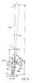
- FIG 3 a construction is shown which replaces the probe of Figures 1 and 2, except that the same or similar mechanism (60A) is used to provide vertical and horizontal displacement of the probe, as needed. Parts similar to those previously described bear the same reference numeral, to which the distinguishing letter "A" is appended.
- probe 40A mounts a disposable tip 48A on a cone surface 68A, with a housing 70A which loosely surrounds a shaft 72A generally as described above for the prior art probe.
- shaft 72A is seated in a depression 90 in a block 92 and the vertical compliance is due to a compression spring 76A surrounding most of shaft 72A.
- the intersection of block 92 by shaft 72A creates the pivot point for the entire probe down to and including tip 48A which is essentially a rigid arm.
- a cone 110 is mounted on the end of shaft 72A, with a conical surface 112 which mates with an opening 114 when spring 76A is fully extended.
- cone 110 has a cylindrical portion 116 which is considerably smaller than the opening 114, so that when cone 110 is pushed up against spring 76A by the tip locator (not shown) at the dispensing station, shaft 72A is free to pivot, in the direction indicated by arrows 120, about pivot point P in depression 90, until cone 110 strikes either opening 114 with cylindrical portion 116, or the inside of housing 70A with upper portion 122 connected to cone surface 112.
- the horizontal extent of the pivoting, as shown by arrows 120 introduces the pending displacement error X' which may or may not be the same quantitative value as error X of the prior art.
- shaft 72A, cone 110 and tip 48A comprise one rigid arm, any displacement error X' which does occur will of course misalign the axis of this rigid arm slightly off vertical. However, the small amount which this disturbs tip 48A from being vertical is of no consequence to the performance of the tip.
- Figure 3 The other features of Figure 3, including compression spring 130, microprocessor 140, sensor 150 and flag 160, are optional and not part of this invention, but are as described in co-pending European patent application no. 93202783 filed concurrently herewith and corresponding to commonly owned US patent application serial no. 954632. They are shown to illustrate that some sensing mechanism is preferred to allow the probe to sense when it and its tip 48A has descended the proper distance to pick up a tip, and preferably, only a tip. The sensing is a function of the movement of flag 160 past the sensor 150. Flag 160 ceases movement when cone 110 ceases movement (shaft 72A having bottomed out in depression 90 and housing 70A continues to advance against spring 130. Detection of the cessation, coupled with the number of flag windows which have gone past the sensor 150, informs the microprocessor how far the probe has descended.
- tip 48A is seated in tip locator 32A and is constrained in the x direction by opening 36A of locator 32A.
- Tip surface 49A and locator surface 34A are the pivotal or fulcrum surfaces. Misalignment of the probe with locator 32A causes a displacement error X' of cone 110, Figure 3, of up to 0.8mm.
- compliant spring 76A ( Figure 3) causes shaft 72A to pivot about point P to return the shaft to its vertical orientation and recover the pending error X'.
- Tip 48A (shown in phantom, Figure 4) pivots on surface 34A to allow this, and this creates tip movement d, the actual displacement error resulting from the "pending" error X'. This movement d gives a reduced amount of "tip flick".
Landscapes
- Chemical & Material Sciences (AREA)
- Health & Medical Sciences (AREA)
- Analytical Chemistry (AREA)
- Chemical Kinetics & Catalysis (AREA)
- Physics & Mathematics (AREA)
- Life Sciences & Earth Sciences (AREA)
- Clinical Laboratory Science (AREA)
- Biochemistry (AREA)
- General Health & Medical Sciences (AREA)
- General Physics & Mathematics (AREA)
- Immunology (AREA)
- Pathology (AREA)
- Automatic Analysis And Handling Materials Therefor (AREA)
Claims (3)
- Ansaugpipette (40A) zum Ansaugen und Ausgeben von Flüssigkeit, umfassend:ein Gehäuse (70A);eine Trägerstange (72A), die im Gehäuse (70A) angeordnet ist; undeine mit der Trägerstange (72A) verbundene Spitzen-Befestigungsfläche (68A) für eine austauschbare Spitze (48A), wobei die Spitze (48A) eine Sitzfläche (49A) und eine Ausgabeöffnung (13A) aufweist, die Trägerstange (72A) im allgemeinen vertikal angeordnet ist und schwenkbare, anpassungsfähige Mittel (76A) einschließtt, die eine horizontale Versetzung der Spitze (48A) in einer Ausgabestation ermöglichen, die äußere, an ihre Sitzfläche (49A) angrenzende Fläche der Spitze (48A) als ein Schwenkpunkt für unbeabsichtigtes Verschwenken der Spitze (48A) in der Ausgabestation wirksam ist, was eine horizontale Versetzung der Ausgabeöffnung (13A) der Spitze (48A) verursacht,dadurch gekennzeichnet, daß das anpassungsfähige Mittel (76A) vertikal längs der Trägerstange (72A) an einem Punkt (P) der Spitzen-Befestigungsfläche (49A) schwenkbar gelagert ist, der mindestens der fünffachen Länge der Spitze (48A) von ihrer Sitzfläche (49A) zu der Ausgabeöffnung (13A) der Spitze (48A) entsprechend entfernt liegt, so daß die horizontale Versetzung der Ausgabeöffnung (13A) aufgrund der unbeabsichtigten Schwenkbewegung möglichst gering ist.
- Pipette gemäß Anspruch 1, wobei das anpassungsfähige Mittel (76A) eine Druckfeder (76A) umfaßt, die zumindest einen Teil der Trägerstange (72A) umgibt.
- Pipette gemäß Anspruch 1 oder 2, wobei die Ausgabestation Mittel zum Halten eines Objektträger-Prüfelementes (E) sowie eine Spitzen-Positioniervorrichtung (32A, 34A, 36A) umfaßt, in die eine Spitze (48A) einsetzbar ist, wobei die Positioniervorrichtung (32A, 34A, 36A) eine Sitzfläche (34A) aufweist, die auf die Sitzfläche (49A) der Spitze (48A) als Stützpunkt wirkt, wenn die Spitze (48A) von der Sitzfläche (34A) der Positioniervorrichtung (32A, 34A, 36A) anfänglich zurückgezogen wird.
Applications Claiming Priority (4)
| Application Number | Priority Date | Filing Date | Title |
|---|---|---|---|
| US954632 | 1992-09-30 | ||
| US07/954,632 US5273717A (en) | 1992-09-30 | 1992-09-30 | Self-calibrating analyzer aspirator |
| US12681 | 1993-02-03 | ||
| US08/012,681 US5344610A (en) | 1993-02-03 | 1993-02-03 | Aspirator probe with long pivot arm to minimize tip flick |
Publications (3)
| Publication Number | Publication Date |
|---|---|
| EP0590730A2 EP0590730A2 (de) | 1994-04-06 |
| EP0590730A3 EP0590730A3 (en) | 1994-09-21 |
| EP0590730B1 true EP0590730B1 (de) | 1997-08-06 |
Family
ID=26683876
Family Applications (1)
| Application Number | Title | Priority Date | Filing Date |
|---|---|---|---|
| EP19930202782 Expired - Lifetime EP0590730B1 (de) | 1992-09-30 | 1993-09-28 | Ansaugpipetten |
Country Status (2)
| Country | Link |
|---|---|
| EP (1) | EP0590730B1 (de) |
| DE (1) | DE69312839T2 (de) |
Families Citing this family (1)
| Publication number | Priority date | Publication date | Assignee | Title |
|---|---|---|---|---|
| JP4558995B2 (ja) * | 2001-09-12 | 2010-10-06 | ベックマン コールター, インコーポレイテッド | 移送ユニットおよびその移送ユニットを備える自動分析装置 |
Family Cites Families (5)
| Publication number | Priority date | Publication date | Assignee | Title |
|---|---|---|---|---|
| GB1392791A (en) * | 1972-02-10 | 1975-04-30 | Suovaniemi Oa | Multiple pipette |
| US4347750A (en) * | 1980-06-16 | 1982-09-07 | Eastman Kodak Company | Potentiometric metering apparatus |
| US4340390A (en) * | 1980-06-16 | 1982-07-20 | Eastman Kodak Company | Method and apparatus for metering biological fluids |
| JP2701900B2 (ja) * | 1988-12-20 | 1998-01-21 | 株式会社ニチリョー | マルチピペット |
| DE4003591A1 (de) * | 1990-02-07 | 1991-08-08 | Joerg Spindler | Mehrkanalpipette mit neigungsspiel an der hubplatte aufweisenden kolben |
-
1993
- 1993-09-28 DE DE1993612839 patent/DE69312839T2/de not_active Expired - Fee Related
- 1993-09-28 EP EP19930202782 patent/EP0590730B1/de not_active Expired - Lifetime
Also Published As
| Publication number | Publication date |
|---|---|
| EP0590730A2 (de) | 1994-04-06 |
| EP0590730A3 (en) | 1994-09-21 |
| DE69312839D1 (de) | 1997-09-11 |
| DE69312839T2 (de) | 1998-01-22 |
Similar Documents
| Publication | Publication Date | Title |
|---|---|---|
| CA2038912C (en) | Fluid dispensing system with optical locator | |
| US5408891A (en) | Fluid probe washing apparatus and method | |
| US4539855A (en) | Apparatus for transferring liquid out of a capped container, and analyzer utilizing same | |
| EP0508531B1 (de) | Flüssigkeitsausgabe mit Behälterbodendetektion | |
| CA1107251A (en) | Probe and syringe drive apparatus | |
| US6238626B1 (en) | Automatic distribution apparatus and method of distribution | |
| US8721966B2 (en) | Chemical analyzer, method for dispensing and dilution cup | |
| US8354078B2 (en) | Liquid aspirating tube, liquid dispensing apparatus and liquid dispensing method | |
| EP1752775B1 (de) | Verfahren zur Prädiktion eines angesaugten Flüssigkeitsvolumen | |
| EP1767950A1 (de) | Verfahren und Vorrichtung zur präzisen Positionierung einer Pipettiervorrichtung | |
| US20120222773A1 (en) | Analyzer and position confirming method | |
| US7517694B2 (en) | Metering tip with internal features to control fluid meniscus and oscillation | |
| CN110291405B (zh) | 自动分析装置和自动分析装置中的清洗机构 | |
| US5344610A (en) | Aspirator probe with long pivot arm to minimize tip flick | |
| US5273717A (en) | Self-calibrating analyzer aspirator | |
| JPH0843403A (ja) | 分析装置 | |
| EP2030690A2 (de) | Automatisches Analysegerät | |
| EP0590730B1 (de) | Ansaugpipetten | |
| JP4949109B2 (ja) | 液体分注装置、検体測定装置および液体分注方法 | |
| JP4945290B2 (ja) | 液体吸引管、液体分注装置および検体測定装置 | |
| JP3408709B2 (ja) | 希釈槽及びこれを用いた希釈装置 | |
| JP2662159B2 (ja) | 自動メスアップシステム | |
| JPS62235570A (ja) | 試料サンプリング装置 | |
| JP2599511Y2 (ja) | 自動試料吸引器用ニードル | |
| JPH0318150B2 (de) |
Legal Events
| Date | Code | Title | Description |
|---|---|---|---|
| PUAI | Public reference made under article 153(3) epc to a published international application that has entered the european phase |
Free format text: ORIGINAL CODE: 0009012 |
|
| AK | Designated contracting states |
Kind code of ref document: A2 Designated state(s): BE CH DE FR GB IE IT LI LU NL |
|
| PUAL | Search report despatched |
Free format text: ORIGINAL CODE: 0009013 |
|
| AK | Designated contracting states |
Kind code of ref document: A3 Designated state(s): BE CH DE FR GB IE IT LI LU NL |
|
| 17P | Request for examination filed |
Effective date: 19950223 |
|
| RAP1 | Party data changed (applicant data changed or rights of an application transferred) |
Owner name: CLINICAL DIAGNOSTIC SYSTEMS, INC. |
|
| RAP1 | Party data changed (applicant data changed or rights of an application transferred) |
Owner name: JOHNSON & JOHNSON CLINICAL DIAGNOSTICS, INC. |
|
| GRAG | Despatch of communication of intention to grant |
Free format text: ORIGINAL CODE: EPIDOS AGRA |
|
| 17Q | First examination report despatched |
Effective date: 19961108 |
|
| GRAH | Despatch of communication of intention to grant a patent |
Free format text: ORIGINAL CODE: EPIDOS IGRA |
|
| GRAH | Despatch of communication of intention to grant a patent |
Free format text: ORIGINAL CODE: EPIDOS IGRA |
|
| GRAA | (expected) grant |
Free format text: ORIGINAL CODE: 0009210 |
|
| AK | Designated contracting states |
Kind code of ref document: B1 Designated state(s): BE CH DE FR GB IE IT LI LU NL |
|
| PG25 | Lapsed in a contracting state [announced via postgrant information from national office to epo] |
Ref country code: NL Free format text: LAPSE BECAUSE OF FAILURE TO SUBMIT A TRANSLATION OF THE DESCRIPTION OR TO PAY THE FEE WITHIN THE PRESCRIBED TIME-LIMIT Effective date: 19970806 Ref country code: IT Free format text: LAPSE BECAUSE OF FAILURE TO SUBMIT A TRANSLATION OF THE DESCRIPTION OR TO PAY THE FEE WITHIN THE PRESCRIBED TIME-LIMIT;WARNING: LAPSES OF ITALIAN PATENTS WITH EFFECTIVE DATE BEFORE 2007 MAY HAVE OCCURRED AT ANY TIME BEFORE 2007. THE CORRECT EFFECTIVE DATE MAY BE DIFFERENT FROM THE ONE RECORDED. Effective date: 19970806 Ref country code: BE Effective date: 19970806 |
|
| REG | Reference to a national code |
Ref country code: CH Ref legal event code: EP |
|
| REG | Reference to a national code |
Ref country code: CH Ref legal event code: NV Representative=s name: E. BLUM & CO. PATENTANWAELTE |
|
| REF | Corresponds to: |
Ref document number: 69312839 Country of ref document: DE Date of ref document: 19970911 |
|
| PG25 | Lapsed in a contracting state [announced via postgrant information from national office to epo] |
Ref country code: LU Free format text: LAPSE BECAUSE OF NON-PAYMENT OF DUE FEES Effective date: 19970930 |
|
| PG25 | Lapsed in a contracting state [announced via postgrant information from national office to epo] |
Ref country code: IE Free format text: LAPSE BECAUSE OF NON-PAYMENT OF DUE FEES Effective date: 19971006 |
|
| ET | Fr: translation filed | ||
| NLV1 | Nl: lapsed or annulled due to failure to fulfill the requirements of art. 29p and 29m of the patents act | ||
| PLBE | No opposition filed within time limit |
Free format text: ORIGINAL CODE: 0009261 |
|
| STAA | Information on the status of an ep patent application or granted ep patent |
Free format text: STATUS: NO OPPOSITION FILED WITHIN TIME LIMIT |
|
| 26N | No opposition filed | ||
| REG | Reference to a national code |
Ref country code: GB Ref legal event code: IF02 |
|
| PGFP | Annual fee paid to national office [announced via postgrant information from national office to epo] |
Ref country code: DE Payment date: 20070920 Year of fee payment: 15 |
|
| REG | Reference to a national code |
Ref country code: CH Ref legal event code: PFA Owner name: JOHNSON & JOHNSON CLINICAL DIAGNOSTICS, INC. Free format text: JOHNSON & JOHNSON CLINICAL DIAGNOSTICS, INC.#100 INDIGO CREEK DRIVE#ROCHESTER NEW YORK 14650 (US) -TRANSFER TO- JOHNSON & JOHNSON CLINICAL DIAGNOSTICS, INC.#100 INDIGO CREEK DRIVE#ROCHESTER NEW YORK 14650 (US) |
|
| PGFP | Annual fee paid to national office [announced via postgrant information from national office to epo] |
Ref country code: CH Payment date: 20070927 Year of fee payment: 15 |
|
| PGFP | Annual fee paid to national office [announced via postgrant information from national office to epo] |
Ref country code: GB Payment date: 20070926 Year of fee payment: 15 |
|
| PGFP | Annual fee paid to national office [announced via postgrant information from national office to epo] |
Ref country code: FR Payment date: 20070914 Year of fee payment: 15 |
|
| REG | Reference to a national code |
Ref country code: CH Ref legal event code: PL |
|
| GBPC | Gb: european patent ceased through non-payment of renewal fee |
Effective date: 20080928 |
|
| REG | Reference to a national code |
Ref country code: FR Ref legal event code: ST Effective date: 20090529 |
|
| PG25 | Lapsed in a contracting state [announced via postgrant information from national office to epo] |
Ref country code: DE Free format text: LAPSE BECAUSE OF NON-PAYMENT OF DUE FEES Effective date: 20090401 |
|
| PG25 | Lapsed in a contracting state [announced via postgrant information from national office to epo] |
Ref country code: LI Free format text: LAPSE BECAUSE OF NON-PAYMENT OF DUE FEES Effective date: 20080930 Ref country code: FR Free format text: LAPSE BECAUSE OF NON-PAYMENT OF DUE FEES Effective date: 20080930 Ref country code: CH Free format text: LAPSE BECAUSE OF NON-PAYMENT OF DUE FEES Effective date: 20080930 |
|
| PG25 | Lapsed in a contracting state [announced via postgrant information from national office to epo] |
Ref country code: GB Free format text: LAPSE BECAUSE OF NON-PAYMENT OF DUE FEES Effective date: 20080928 |