EP0589974B1 - Verfahren und system zur prüfung kapazitiver akustischer wandler - Google Patents
Verfahren und system zur prüfung kapazitiver akustischer wandler Download PDFInfo
- Publication number
- EP0589974B1 EP0589974B1 EP92912298A EP92912298A EP0589974B1 EP 0589974 B1 EP0589974 B1 EP 0589974B1 EP 92912298 A EP92912298 A EP 92912298A EP 92912298 A EP92912298 A EP 92912298A EP 0589974 B1 EP0589974 B1 EP 0589974B1
- Authority
- EP
- European Patent Office
- Prior art keywords
- capacity
- test conduit
- test
- preamplifier
- conduit
- Prior art date
- Legal status (The legal status is an assumption and is not a legal conclusion. Google has not performed a legal analysis and makes no representation as to the accuracy of the status listed.)
- Revoked
Links
- 238000012360 testing method Methods 0.000 title claims description 69
- 238000000034 method Methods 0.000 title claims description 11
- 239000003990 capacitor Substances 0.000 claims description 27
- 239000002775 capsule Substances 0.000 claims description 13
- 238000005476 soldering Methods 0.000 claims description 5
- 239000000758 substrate Substances 0.000 claims description 4
- 238000010998 test method Methods 0.000 claims description 4
- 238000005259 measurement Methods 0.000 claims description 3
- 239000012528 membrane Substances 0.000 description 5
- 230000003321 amplification Effects 0.000 description 3
- 239000004020 conductor Substances 0.000 description 3
- 230000005672 electromagnetic field Effects 0.000 description 3
- 238000003199 nucleic acid amplification method Methods 0.000 description 3
- 230000035945 sensitivity Effects 0.000 description 2
- XLYOFNOQVPJJNP-UHFFFAOYSA-N water Substances O XLYOFNOQVPJJNP-UHFFFAOYSA-N 0.000 description 2
- 230000005540 biological transmission Effects 0.000 description 1
- 230000007547 defect Effects 0.000 description 1
- 238000009413 insulation Methods 0.000 description 1
- 239000002184 metal Substances 0.000 description 1
- 244000045947 parasite Species 0.000 description 1
Images

Classifications
-
- G—PHYSICS
- G01—MEASURING; TESTING
- G01R—MEASURING ELECTRIC VARIABLES; MEASURING MAGNETIC VARIABLES
- G01R31/00—Arrangements for testing electric properties; Arrangements for locating electric faults; Arrangements for electrical testing characterised by what is being tested not provided for elsewhere
- G01R31/28—Testing of electronic circuits, e.g. by signal tracer
- G01R31/282—Testing of electronic circuits specially adapted for particular applications not provided for elsewhere
- G01R31/2829—Testing of circuits in sensor or actuator systems
Definitions
- the invention relates to a method of testing one or more capacitive transducers from a central control unit, where the transducers are individually connected to an inlet of a preamplifier having a relatively high input resistance, and where a test conduit furthermore extends from the central control unit to the transducers, the testing of each transducer being performed by means of a test signal transmitted through the test conduit and a relatively small capacity inserted in said test conduit to the joint between the transducer and the inlet of the preamplifier.
- each microphone is connected to the inlet of a preamplifier having a relatively high input resistance.
- the microphones may be placed far away from a central control unit performing the testing optinally automatically.
- a test signal is transmitted through an individual test conduit from the central control unit to each microphone.
- the test conduit is connected to the chassis terminal of the microphone.
- the test signal is transmitted through the capacity of the microphone.
- Modern preamplifiers ensure that the response to the test signal is almost independent of the capacity of the microphone, and accordingly it is not possible to detect changes therein although said capacity has become extremely high or optionally shortcircuits.
- Elder preamplifiers with a relatively high input capacity provide a slight sensitivity to changes in the capacity of the transducer.
- This sensitivity is, however, very small, typically of a magnitude smaller than the one achievable by the method according to the invention.
- external electromagnetic fields presents a technical problem, especially in connection with large measuring systems.
- the measuring system associated with the known central control unit is sensitive to external fields due to the separate chassis terminals of the microphone and the preamplifier.
- US-PS No. 4,648,078 discloses a system for testing a plurality of acoustic transducers, a test signal being transmitted through the capacity between the screen and the inner conductor of a screened cable to the joint between the individual transducer and an amplifier. This system is, however, only able to indicate whether the amplifier and the cable to a central control unit is in order. The system is unable to indicate whether the capacity of the transducer has changed.
- US-PS No. 3,230,449 relates to an apparatus for measurement of a capacity. A test signal is led out to the joint between the capacity and an amplifier. However, it is not stated that it is possible to record the frequency characteristics. Nor has remote control of capacitive transducers been mentioned.
- the object of the invention is to provide a method of the above type, which is highly sensitive to the condition of each transducer simultaneously with being relatively insensitive to external electromagnetic fields.
- a method of the above type is according to the invention characterised by selecting the capacity inserted in the test conduit to have a very high equivalent parallel resistance or leakage resistances, which is large compared to the impedance of the capacity and measuring the frequency characteristics f. inst. at one or more discrete frequencies via the test conduit and comparing the measurement frequency characteristics with previously determined characteristics so as to indicate errors, if any, in the transducer, the test conduit in the control unit communicating with a change-over switch connected to either a chassis or a test AC voltage.
- the high equivalent parallel resistance the leakage resistance, of the capacity renders it possible to perform a testing even at the lowest operational frequencies in such a manner that it is possible to find the frequency characteristics and thereby to indicate errors, if any, in the transducer.
- the equivalent parallel resistance (leakage resistance) of the capacity in the test conduit may be about 10 7 M ⁇ .
- the capacity in the test conduit may for instance be provided by means of a substrate with a soldering layer on one side and a conducting path on the opposite side.
- the resulting capacity is provided with a very high parallel resistance or parasite resistance. As a result it is also possible to perform tests at the lowest operational frequencies.
- the invention relates furthermore to a system for carrying out the method of testing one or more transducers from a central control unit, where the transducers are individually connected to an inlet of a preamplifier having a relatively high input resistance, and where a test conduit from the central control unit is connected to each of the transducers, wherein the test conduit is connected to the joint between the transducer and the inlet of the preamplifier through a relatively small capacity.
- the system is characterised by the relatively small capacity in the test conduit having a very high equivalent parallel resistance or leakage resistance, which is large compared to the impedance of the capacity and by the test conduit in the control unit communicating with a change-over switch connected to either a chassis or a test AC voltage.
- the capacity in the test conduit may be an adjustable screw in a capsule, said adjustable screw being electrically insulated from the remaining portion of the capsule.
- the capacity in the test conduit may be an adjustable screw in an adapter in form of a separate unit between the capsule and the preamplifier. Such a unit can be delivered separately together with the necessary supply lines.
- the invention relates to a method of testing transducers, such as microphones, which can be arranged far from a central control unit.
- transducers such as microphones
- the most noisy aircrafts are sometimes penalized by fewer landing permits or optionally fined.
- the reliability of the accuracy of the measuring system is of decisive importance because an exceeding of the alldwed noise limits can have very serious consequences.
- Fig. 1 illustrates a known microphone unit comprising a capacitor microphone 2 and a preamplifier 4.
- the value of the capacitor 5 corresponds to the input capacity of the preamplifier 4 plus the capacitor of the supply line.
- the input resistance 6 corresponds to the input resistance of the preamplifier 4.
- the capacitor 5 and the resistance 6 are typically of a value of 0.2 pF and 5 ⁇ 10 10 ⁇ .
- the capacity of the microphone 2 is approximately 20 pF.
- a test conduit 8 is connected to one input terminal of the microphone 2, whereby a test signal of for instance 100 mV can be transmitted at one or more discrete frequencies through the test conduit 8 and a change-over switch 1 in the central control unit.
- the system according to the invention is so sensitive that even minor changes of 1% can be detected. Minor changes can for instance be caused by the parts of the microphone 2 being warped relative to one another, or by the membrane in the microphone being slackened to such a degree that it is pulled towards a backplate electrode of an electrical polarisation voltage between the membrane and the backplate electrode.
- a broken membrane or a drop of water in the microphone can cause substantial measuring errors by shortcircuiting the capacity of the microphone. Such serious errors can be detected by the central unit because the voltage ratio changes from 0.83 to 0.95.
- the system is, however, rather insensitive to changes in the capacity and insignificant changes cannot be detected.
- the system according to the invention involves such a proportional relationship that a change in capacity of for instance 5% results in a change in the output signal V out of 5%.
- the known capacitor microphone requires an insulation between the capsule and the remaining portion of the microphone including the preamplifier 4 as these portions must be mutually insulated during the transmission 5 of the test signal.
- the change-over switch 1 in the central control unit connects the capacitor microphone 2 either to a test voltage of about 100 mV or to the chassis. The connecting to the chassis through the change-over switch 1 in the central control unit is thereby performed through a relatively long conducting path implying that irrelevant signals can be picked up.
- the test conduit 8' includes a relatively small capacitor 10 connected to the joint between the capacitor microphone 2 and the input of the preamplifier 4.
- the capacitor 10 is of a magnitude of about 0.1 pF, i.e, of the same magnitude as the capacity 5.
- the parallel resistance (the leakage resistance) of the capacitor 10 must, however, be of the magnitude 10 7 M ⁇ in order to allow the leakage current to be about 100 times smaller than the capacity current of the capacitor 10, as an unacceptable frequency nonlinearity is otherwise found in the lower portion of the frequency range.
- a parallel resistance (leakage resistance) must apply which is of the magnitude 10 7 M ⁇ in order to test a typical capacitor microphone system at a low cut-off frequency of for instance 20 Hz.
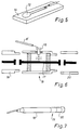
- Such a small capacitor 10 with a high leakage resistance is according to the invention provided by means of a substrate 14, cf. Fig. 5, provided with a soldering layer 12 on one side and a conducting path (not shown) on the opposite side.
- the leakage currents are thereby very small with the result that the capacity is very low and can be trimmed by cutting off portions of the soldering layer 12 by means of a laser beam or other abrasive means.
- the substrate can for instance be formed by the circuit card provided with the preamplifier 4.
- V in 10 V
- C c 0.1 pF
- C m 20 pF
- C i 0.2 pF
- A 0.995
- V out is almost o.
- a testing at several different frequencies can reveal whether the frequency characteristic has been changed relative to earlier measured characteristics, and the source of error can be evaluated.
- the leakage resistance is very high, in practise of the magnitude 10 7 M ⁇ .
- the stability of the capacity must typically be so good that neither the temperature nor the time results in changes exceeding 1%.
- the capacity is typically 100 times smaller than the capacity of the microphone, i.e. 0.1 pF or lower.
- the relatively small capacitor in the test conduit 8' can alternatively be provided in form of an adjustable screw 16 in the microphone capsule 20 or in an adapter 19 between the capsule 20 and the preamplifier, said screw 16 being electrically insulated from the remaining portion of the capsule or the adapter.
- the adjustable screw 16 possesses a low capacity relative to a permanently supported conduit 17 providing the connection between the capacitor microphone and the preamplifier, cf. Fig. 6.
- the test conduit 8' is connected to the screw 16. The only important feature is that the capacity is very stable. The exact value of the capacity need not necessarily be known provided it is stable.
- Fig. 7 illustrates the entire microphone unit comprising the encapsulated preamplifier 18, the adapter 19, and the microphone capsule 20.
- the method according to the invention can also be used in connection with other capacitive transducers, such as piezoelectric hydrophones and accelerometers, and it can for instance be used for controlling whether an accelerometer has been correctly mounted.
- capacitive transducers such as piezoelectric hydrophones and accelerometers
- the system according to the invention is furthermore rather insensitive to external electromagnetic fields, such as radar fields adjacent an airport, because the conductor path from the chassis terminal of the microphone to the chassis terminal of the preamplifier is very short. In other words, a very efficient chassis connection is obtained.
- the important factor is that the measuring accuracy is known, and furthermore that said accuracy does not change gradually. Only then it is possible to determine the fines relating to an exceeding of the allowed noise level.
- the conductor from the transducer and each preamplifier to the central unit are also tested.
Landscapes
- Physics & Mathematics (AREA)
- Electromagnetism (AREA)
- Engineering & Computer Science (AREA)
- General Engineering & Computer Science (AREA)
- General Physics & Mathematics (AREA)
- Electrostatic, Electromagnetic, Magneto- Strictive, And Variable-Resistance Transducers (AREA)
- Measurement Of Resistance Or Impedance (AREA)
- Examining Or Testing Airtightness (AREA)
- Measurement Of Mechanical Vibrations Or Ultrasonic Waves (AREA)
- Testing Electric Properties And Detecting Electric Faults (AREA)
Claims (10)
- Verfahren zum Testen eines oder mehrerer kapazitiver Wandler durch eine zentrale Steuereinheit, wobei jeder Wandler mit einem Eingang eines Vorverstärkers (4) mit relativ hohem Eingangswiderstand (6) verbunden ist und wobei sich eine Prüfleitung von der zentralen Steuereinheit zu den Wandlern erstreckt, wobei die Prüfung jedes Wandlers mit Hilfe eines Prüfsignals ausgeführt wird, das über die Prüfleitung (8') übertragen wird und wobei ein Kondensator relativ kleiner Kapazität in der Prüfleitung (8') zu der Verbindung zwischen dem Wandler und dem Eingang des Vorverstärkers (4) eingefügt ist, gekennzeichnet durch Auswahl der in der Prüfleitung (8') eingefügten Kapazität (10) mit einem sehr hohen äquivalenten Parallelwiderstand oder Leckwiderstand, der im Vergleich zur Impedanz der Kapazität (10) groß ist, und Messen der Frequenzkennwerte z.B. bei einer oder mehreren diskreten Frequenzen über die Prüfleitung (8') und Vergleichen der gemessenen Frequenzkennwerte mit vorher ermittelten Kennwerten, um gegebenenfalls in dem Wandler auftretende Fehler zu erkennen, wobei die Prüfleitung (8') in der Steuereinheit mit einem Wechselschalter (1) in Verbindung steht, der entweder mit einem Gehäuse oder einer Prüf-Wechselspannung verbunden ist.
- Verfahren nach Anspruch 1, dadurch gekennzeichnet, daß die Kapazität (10) in der Prüfleitung (8') einen Wert von etwa 0,1 pF aufweist.
- Verfahren nach Anspruch 2, dadurch gekennzeichnet, daß der äquivalente Parallelwiderstand oder Leckwiderstand der Kapazität (10) in der Prüfleitung (8') etwa 107 MΩ beträgt.
- Verfahren nach Anspruch 2 oder 3, dadurch gekennzeichnet, daß die Kapazität (10) in der Prüfleitung (8') mittels eines Substrats (14) mit einer Lötschicht (12) auf der einen Seite und mit einer Leiterbahn auf der gegenüberliegenden Seite versehen ist.
- Verfahren nach Anspruch 4, dadurch gekennzeichnet, daß die Lötschicht (12) mittels eines Laserstrahls oder einer anderen Abtrageinrichtung beschnitten wird, bis die gewünschte Kapazität des Kondensators (10) erreicht worden ist.
- System zum Ausführen des Verfahrens nach einem oder mehreren der vorstehenden Ansprüche 1 bis 5 zum Prüfen eines oder mehrerer Wandler von einer zentralen Steuereinheit aus, wobei die Wandler einzeln mit einem Eingang eines Vorverstärkers (4) mit relativ hohem Eingangswiderstand (6) verbunden sind und wobei eine Prüfleitung von der zentralen Steuereinheit mit jedem der Wandler verbunden ist, wobei die Prüfleitung (8') mit dem Verbindungspunkt zwischen dem Wandler und dem Eingang des Vorverstärkers (4) über eine relativ geringe Kapazität (10) verbunden ist, dadurch gekennzeichnet, daß die relativ kleine Kapazität in der Prüfleitung (8') einen sehr hohen äquivalenten Parallelwiderstand oder Leckwiderstand aufweist, der im Vergleich zur Impedanz der Kapazität (10) groß ist, und wobei die Prüfleitung (8') mit einem Umschalter (1) in der Steuereinheit in Verbindung steht, wobei der Umschalter entweder mit einem Gehäuse oder einer Prüf-Wechselspannung verbunden ist.
- Systen nach Anspruch 6, dadurch gekennzeichnet, daß die Kapazität (10) in der Prüfleitung (8') einen Wert von etwa 0,1 pF aufweist.
- System nach einem der Ansprüche 6 bis 7, dadurch gekennzeichnet, daß der äquivalente Parallelwiderstand der Kapazität (10) eine Größenordnung von 107 MΩ aufweist.
- System nach einem der Ansprüche 6 bis 8, dadurch gekennzeichnet, daß die Kapazität der Prüfleitung (8') eine einstellbare Schraube in einer Kapsel (20) ist, wobei die einstellbare Schraube gegenüber dem verbleibenden Abschnitt der Kapsel elektrisch isoliert ist.
- System nach einem der Ansprüche 6 bis 8, dadurch gekennzeichnet, daß die Kapazität der Prüfleitung (8') eine einstellbare Schraube (16) in einem Adapter (19) in Form einer getrennten Einheit zwischen der Kapsel (20) und dem Vorverstärker (18) ist.
Applications Claiming Priority (4)
| Application Number | Priority Date | Filing Date | Title |
|---|---|---|---|
| DK105091A DK167636B1 (da) | 1991-05-31 | 1991-05-31 | Fremgangsmaade og apparat til overvaagning af akustiske transducere |
| DK105091 | 1991-05-31 | ||
| DK1050/91 | 1991-05-31 | ||
| PCT/DK1992/000173 WO1992021982A1 (en) | 1991-05-31 | 1992-05-29 | A method and a system for testing capacitive acoustic transducers |
Publications (2)
| Publication Number | Publication Date |
|---|---|
| EP0589974A1 EP0589974A1 (de) | 1994-04-06 |
| EP0589974B1 true EP0589974B1 (de) | 1998-07-08 |
Family
ID=8100414
Family Applications (1)
| Application Number | Title | Priority Date | Filing Date |
|---|---|---|---|
| EP92912298A Revoked EP0589974B1 (de) | 1991-05-31 | 1992-05-29 | Verfahren und system zur prüfung kapazitiver akustischer wandler |
Country Status (7)
| Country | Link |
|---|---|
| US (1) | US5400297A (de) |
| EP (1) | EP0589974B1 (de) |
| JP (2) | JPH06508685A (de) |
| AU (1) | AU1978092A (de) |
| DE (2) | DE69226186T2 (de) |
| DK (2) | DK167636B1 (de) |
| WO (1) | WO1992021982A1 (de) |
Cited By (1)
| Publication number | Priority date | Publication date | Assignee | Title |
|---|---|---|---|---|
| US11277701B2 (en) | 2019-09-12 | 2022-03-15 | iSEMcon GmbH | Microphone |
Families Citing this family (8)
| Publication number | Priority date | Publication date | Assignee | Title |
|---|---|---|---|---|
| US5736631A (en) * | 1996-03-11 | 1998-04-07 | Turf Diagnostics & Design, Inc. | Turf impact analysis system |
| RU2132116C1 (ru) * | 1997-07-02 | 1999-06-20 | Ястребов Анатолий Степанович | Способ определения качества электретных электроакустических преобразователей и устройство для его реализации |
| US7028529B2 (en) * | 2003-04-28 | 2006-04-18 | Sonora Medical Systems, Inc. | Apparatus and methods for testing acoustic probes and systems |
| US7450474B2 (en) * | 2004-02-25 | 2008-11-11 | Lockheed Martin Corporation | Diagnostic system and method for transducers |
| DE602005017308D1 (de) * | 2004-08-31 | 2009-12-03 | Toshiba Kk | Untersuchungsapparat mit Ultraschallsonde, Ultraschalluntersuchungsgerät und Untersuchungsmethode mit einer Ultraschallsonde |
| US7936175B2 (en) * | 2008-05-13 | 2011-05-03 | Brüel & Kjaer Sound & Vibration Measurement A/S | Full function test for in situ test of sensors and amplifiers |
| GB2466777B (en) * | 2008-12-30 | 2011-05-04 | Wolfson Microelectronics Plc | Apparatus and method for testing a transducer and/or electronic circuitry associated with a transducer |
| GB2466785B (en) | 2008-12-30 | 2011-06-08 | Wolfson Microelectronics Plc | Apparatus and method for testing a capacitive transducer and/or associated electronic circuitry |
Family Cites Families (4)
| Publication number | Priority date | Publication date | Assignee | Title |
|---|---|---|---|---|
| US3230449A (en) * | 1961-10-02 | 1966-01-18 | Lockheed Aircraft Corp | Apparatus for direct measurement of capacitance and dissipation factor of capacitors |
| DE3322765A1 (de) * | 1983-06-24 | 1985-01-03 | Fried. Krupp Gmbh, 4300 Essen | Verfahren zur fehlerpruefung einer unterwasserantenne |
| GB2148502B (en) * | 1983-10-18 | 1986-12-31 | Standard Telephones Cables Ltd | Remote calibration of acoustic transducer array |
| US4942614A (en) * | 1986-04-16 | 1990-07-17 | Australian Atomic Energy Commission | Calibration of ultrasonic transducers |
-
1991
- 1991-05-31 DK DK105091A patent/DK167636B1/da not_active IP Right Cessation
-
1992
- 1992-05-29 EP EP92912298A patent/EP0589974B1/de not_active Revoked
- 1992-05-29 DK DK92912298T patent/DK0589974T3/da active
- 1992-05-29 WO PCT/DK1992/000173 patent/WO1992021982A1/en not_active Ceased
- 1992-05-29 AU AU19780/92A patent/AU1978092A/en not_active Abandoned
- 1992-05-29 JP JP4511033A patent/JPH06508685A/ja active Pending
- 1992-05-29 DE DE69226186T patent/DE69226186T2/de not_active Revoked
- 1992-05-29 DE DE0589974T patent/DE589974T1/de active Pending
-
1993
- 1993-11-30 US US08/150,176 patent/US5400297A/en not_active Expired - Lifetime
-
2000
- 2000-10-23 JP JP2000007588U patent/JP2607858Y2/ja not_active Expired - Lifetime
Cited By (1)
| Publication number | Priority date | Publication date | Assignee | Title |
|---|---|---|---|---|
| US11277701B2 (en) | 2019-09-12 | 2022-03-15 | iSEMcon GmbH | Microphone |
Also Published As
| Publication number | Publication date |
|---|---|
| DE589974T1 (de) | 1997-03-13 |
| DE69226186D1 (de) | 1998-08-13 |
| EP0589974A1 (de) | 1994-04-06 |
| DK105091A (da) | 1992-12-01 |
| JPH06508685A (ja) | 1994-09-29 |
| DK105091D0 (da) | 1991-05-31 |
| US5400297A (en) | 1995-03-21 |
| AU1978092A (en) | 1993-01-08 |
| WO1992021982A1 (en) | 1992-12-10 |
| DK0589974T3 (da) | 1999-02-01 |
| DE69226186T2 (de) | 1998-10-22 |
| JP2607858Y2 (ja) | 2003-03-31 |
| JP2001000019U (ja) | 2001-05-18 |
| DK167636B1 (da) | 1993-11-29 |
Similar Documents
| Publication | Publication Date | Title |
|---|---|---|
| US6930494B2 (en) | Capacitive probe assembly with flex circuit | |
| US7936175B2 (en) | Full function test for in situ test of sensors and amplifiers | |
| US5057848A (en) | Broadband frequency meter probe | |
| US5621327A (en) | System and method for testing and fault isolation of high density passive boards and substrates | |
| CZ384996A3 (en) | Method of monitoring internal partial discharges method of monitoring internal partial discharges in power transformer and apparatus for making the in power transformer and apparatus for making the same same | |
| JPH0242196B2 (de) | ||
| US5400297A (en) | Method and a system for testing capacitive, acoustic transducers | |
| SE441310B (sv) | Anordning for legesbestemning av fel pa en flerledarkabel | |
| US4052694A (en) | Method and apparatus for diagnosing faults in the geophone group of a geophysical data acquisition system | |
| US10884045B2 (en) | Test arrangement and test method | |
| US6714023B2 (en) | Method for high-accuracy non-contact capacitive displacement measurement of poorly connected targets | |
| JPH04249778A (ja) | 電気ケーブル監視装置 | |
| CN110007370B (zh) | 一种通用检波器测试系统及其控制方法 | |
| US6984995B2 (en) | Device to audibly express impendance measurement | |
| US5055828A (en) | Parasitic-ground current indicator for electrical system | |
| JPS6156979A (ja) | 電力ケ−ブルの絶縁測定方法 | |
| JPS60216695A (ja) | スピ−カ試験装置 | |
| JPH0275087A (ja) | 磁気ラインセンサ | |
| JP3196974B2 (ja) | 検電器 | |
| AU2001296209A1 (en) | A device for impedance measurement | |
| JPH05196678A (ja) | 電気回路試験装置 | |
| US11277701B2 (en) | Microphone | |
| SU1606115A1 (ru) | Реоплетизмограф | |
| JP2537030Y2 (ja) | Lsiテスタ | |
| JPH02192215A (ja) | ノイズ障害軽減回路 |
Legal Events
| Date | Code | Title | Description |
|---|---|---|---|
| PUAI | Public reference made under article 153(3) epc to a published international application that has entered the european phase |
Free format text: ORIGINAL CODE: 0009012 |
|
| 17P | Request for examination filed |
Effective date: 19931111 |
|
| AK | Designated contracting states |
Kind code of ref document: A1 Designated state(s): DE DK FR GB |
|
| 17Q | First examination report despatched |
Effective date: 19961106 |
|
| DET | De: translation of patent claims | ||
| GRAG | Despatch of communication of intention to grant |
Free format text: ORIGINAL CODE: EPIDOS AGRA |
|
| GRAG | Despatch of communication of intention to grant |
Free format text: ORIGINAL CODE: EPIDOS AGRA |
|
| GRAG | Despatch of communication of intention to grant |
Free format text: ORIGINAL CODE: EPIDOS AGRA |
|
| GRAH | Despatch of communication of intention to grant a patent |
Free format text: ORIGINAL CODE: EPIDOS IGRA |
|
| GRAH | Despatch of communication of intention to grant a patent |
Free format text: ORIGINAL CODE: EPIDOS IGRA |
|
| GRAA | (expected) grant |
Free format text: ORIGINAL CODE: 0009210 |
|
| AK | Designated contracting states |
Kind code of ref document: B1 Designated state(s): DE DK FR GB |
|
| REF | Corresponds to: |
Ref document number: 69226186 Country of ref document: DE Date of ref document: 19980813 |
|
| ET | Fr: translation filed | ||
| REG | Reference to a national code |
Ref country code: DK Ref legal event code: T3 |
|
| PLBQ | Unpublished change to opponent data |
Free format text: ORIGINAL CODE: EPIDOS OPPO |
|
| PLBI | Opposition filed |
Free format text: ORIGINAL CODE: 0009260 |
|
| PLBQ | Unpublished change to opponent data |
Free format text: ORIGINAL CODE: EPIDOS OPPO |
|
| PLBI | Opposition filed |
Free format text: ORIGINAL CODE: 0009260 |
|
| 26 | Opposition filed |
Opponent name: MUELLER-BBM GMBH Effective date: 19990303 |
|
| 26 | Opposition filed |
Opponent name: G.R.A.S. SOUND & VIBRATION Effective date: 19990326 Opponent name: MUELLER-BBM GMBH Effective date: 19990303 |
|
| PLBF | Reply of patent proprietor to notice(s) of opposition |
Free format text: ORIGINAL CODE: EPIDOS OBSO |
|
| PLBF | Reply of patent proprietor to notice(s) of opposition |
Free format text: ORIGINAL CODE: EPIDOS OBSO |
|
| REG | Reference to a national code |
Ref country code: GB Ref legal event code: IF02 |
|
| PLBQ | Unpublished change to opponent data |
Free format text: ORIGINAL CODE: EPIDOS OPPO |
|
| PLAB | Opposition data, opponent's data or that of the opponent's representative modified |
Free format text: ORIGINAL CODE: 0009299OPPO |
|
| R26 | Opposition filed (corrected) |
Opponent name: G.R.A.S. SOUND & VIBRATION Effective date: 19990326 Opponent name: MUELLER-BBM GMBH Effective date: 19990303 |
|
| PLBQ | Unpublished change to opponent data |
Free format text: ORIGINAL CODE: EPIDOS OPPO |
|
| PLAB | Opposition data, opponent's data or that of the opponent's representative modified |
Free format text: ORIGINAL CODE: 0009299OPPO |
|
| R26 | Opposition filed (corrected) |
Opponent name: G.R.A.S. SOUND & VIBRATION Effective date: 19990326 Opponent name: MUELLER-BBM GMBH Effective date: 19990303 |
|
| RDAF | Communication despatched that patent is revoked |
Free format text: ORIGINAL CODE: EPIDOSNREV1 |
|
| APBP | Date of receipt of notice of appeal recorded |
Free format text: ORIGINAL CODE: EPIDOSNNOA2O |
|
| APAH | Appeal reference modified |
Free format text: ORIGINAL CODE: EPIDOSCREFNO |
|
| APBQ | Date of receipt of statement of grounds of appeal recorded |
Free format text: ORIGINAL CODE: EPIDOSNNOA3O |
|
| PLBP | Opposition withdrawn |
Free format text: ORIGINAL CODE: 0009264 |
|
| PGFP | Annual fee paid to national office [announced via postgrant information from national office to epo] |
Ref country code: DK Payment date: 20070523 Year of fee payment: 16 |
|
| PGFP | Annual fee paid to national office [announced via postgrant information from national office to epo] |
Ref country code: DE Payment date: 20070524 Year of fee payment: 16 |
|
| APBU | Appeal procedure closed |
Free format text: ORIGINAL CODE: EPIDOSNNOA9O |
|
| RDAG | Patent revoked |
Free format text: ORIGINAL CODE: 0009271 |
|
| STAA | Information on the status of an ep patent application or granted ep patent |
Free format text: STATUS: PATENT REVOKED |
|
| 27W | Patent revoked |
Effective date: 20070515 |
|
| GBPR | Gb: patent revoked under art. 102 of the ep convention designating the uk as contracting state |
Free format text: 20070515 |
|
| PGFP | Annual fee paid to national office [announced via postgrant information from national office to epo] |
Ref country code: GB Payment date: 20070521 Year of fee payment: 16 |
|
| PGFP | Annual fee paid to national office [announced via postgrant information from national office to epo] |
Ref country code: FR Payment date: 20070430 Year of fee payment: 16 |
|
| PLAB | Opposition data, opponent's data or that of the opponent's representative modified |
Free format text: ORIGINAL CODE: 0009299OPPO |