EP0589771B1 - Dispositif de fabrication de cartes à puces - Google Patents
Dispositif de fabrication de cartes à puces Download PDFInfo
- Publication number
- EP0589771B1 EP0589771B1 EP93402292A EP93402292A EP0589771B1 EP 0589771 B1 EP0589771 B1 EP 0589771B1 EP 93402292 A EP93402292 A EP 93402292A EP 93402292 A EP93402292 A EP 93402292A EP 0589771 B1 EP0589771 B1 EP 0589771B1
- Authority
- EP
- European Patent Office
- Prior art keywords
- cards
- station
- belt
- positioning
- milling
- Prior art date
- Legal status (The legal status is an assumption and is not a legal conclusion. Google has not performed a legal analysis and makes no representation as to the accuracy of the status listed.)
- Expired - Lifetime
Links
Images



Classifications
-
- G—PHYSICS
- G06—COMPUTING OR CALCULATING; COUNTING
- G06K—GRAPHICAL DATA READING; PRESENTATION OF DATA; RECORD CARRIERS; HANDLING RECORD CARRIERS
- G06K19/00—Record carriers for use with machines and with at least a part designed to carry digital markings
- G06K19/06—Record carriers for use with machines and with at least a part designed to carry digital markings characterised by the kind of the digital marking, e.g. shape, nature, code
- G06K19/067—Record carriers with conductive marks, printed circuits or semiconductor circuit elements, e.g. credit or identity cards also with resonating or responding marks without active components
- G06K19/07—Record carriers with conductive marks, printed circuits or semiconductor circuit elements, e.g. credit or identity cards also with resonating or responding marks without active components with integrated circuit chips
- G06K19/077—Constructional details, e.g. mounting of circuits in the carrier
- G06K19/07745—Mounting details of integrated circuit chips
-
- G—PHYSICS
- G06—COMPUTING OR CALCULATING; COUNTING
- G06K—GRAPHICAL DATA READING; PRESENTATION OF DATA; RECORD CARRIERS; HANDLING RECORD CARRIERS
- G06K19/00—Record carriers for use with machines and with at least a part designed to carry digital markings
- G06K19/06—Record carriers for use with machines and with at least a part designed to carry digital markings characterised by the kind of the digital marking, e.g. shape, nature, code
- G06K19/067—Record carriers with conductive marks, printed circuits or semiconductor circuit elements, e.g. credit or identity cards also with resonating or responding marks without active components
- G06K19/07—Record carriers with conductive marks, printed circuits or semiconductor circuit elements, e.g. credit or identity cards also with resonating or responding marks without active components with integrated circuit chips
- G06K19/077—Constructional details, e.g. mounting of circuits in the carrier
-
- Y—GENERAL TAGGING OF NEW TECHNOLOGICAL DEVELOPMENTS; GENERAL TAGGING OF CROSS-SECTIONAL TECHNOLOGIES SPANNING OVER SEVERAL SECTIONS OF THE IPC; TECHNICAL SUBJECTS COVERED BY FORMER USPC CROSS-REFERENCE ART COLLECTIONS [XRACs] AND DIGESTS
- Y10—TECHNICAL SUBJECTS COVERED BY FORMER USPC
- Y10T—TECHNICAL SUBJECTS COVERED BY FORMER US CLASSIFICATION
- Y10T156/00—Adhesive bonding and miscellaneous chemical manufacture
- Y10T156/12—Surface bonding means and/or assembly means with cutting, punching, piercing, severing or tearing
- Y10T156/1304—Means making hole or aperture in part to be laminated
- Y10T156/1309—Means making hole or aperture in part to be laminated and securing separate part over hole or aperture
-
- Y—GENERAL TAGGING OF NEW TECHNOLOGICAL DEVELOPMENTS; GENERAL TAGGING OF CROSS-SECTIONAL TECHNOLOGIES SPANNING OVER SEVERAL SECTIONS OF THE IPC; TECHNICAL SUBJECTS COVERED BY FORMER USPC CROSS-REFERENCE ART COLLECTIONS [XRACs] AND DIGESTS
- Y10—TECHNICAL SUBJECTS COVERED BY FORMER USPC
- Y10T—TECHNICAL SUBJECTS COVERED BY FORMER US CLASSIFICATION
- Y10T156/00—Adhesive bonding and miscellaneous chemical manufacture
- Y10T156/17—Surface bonding means and/or assemblymeans with work feeding or handling means
- Y10T156/1702—For plural parts or plural areas of single part
- Y10T156/1744—Means bringing discrete articles into assembled relationship
-
- Y—GENERAL TAGGING OF NEW TECHNOLOGICAL DEVELOPMENTS; GENERAL TAGGING OF CROSS-SECTIONAL TECHNOLOGIES SPANNING OVER SEVERAL SECTIONS OF THE IPC; TECHNICAL SUBJECTS COVERED BY FORMER USPC CROSS-REFERENCE ART COLLECTIONS [XRACs] AND DIGESTS
- Y10—TECHNICAL SUBJECTS COVERED BY FORMER USPC
- Y10T—TECHNICAL SUBJECTS COVERED BY FORMER US CLASSIFICATION
- Y10T156/00—Adhesive bonding and miscellaneous chemical manufacture
- Y10T156/17—Surface bonding means and/or assemblymeans with work feeding or handling means
- Y10T156/1702—For plural parts or plural areas of single part
- Y10T156/1744—Means bringing discrete articles into assembled relationship
- Y10T156/1768—Means simultaneously conveying plural articles from a single source and serially presenting them to an assembly station
- Y10T156/1771—Turret or rotary drum-type conveyor
-
- Y—GENERAL TAGGING OF NEW TECHNOLOGICAL DEVELOPMENTS; GENERAL TAGGING OF CROSS-SECTIONAL TECHNOLOGIES SPANNING OVER SEVERAL SECTIONS OF THE IPC; TECHNICAL SUBJECTS COVERED BY FORMER USPC CROSS-REFERENCE ART COLLECTIONS [XRACs] AND DIGESTS
- Y10—TECHNICAL SUBJECTS COVERED BY FORMER USPC
- Y10T—TECHNICAL SUBJECTS COVERED BY FORMER US CLASSIFICATION
- Y10T156/00—Adhesive bonding and miscellaneous chemical manufacture
- Y10T156/17—Surface bonding means and/or assemblymeans with work feeding or handling means
- Y10T156/1702—For plural parts or plural areas of single part
- Y10T156/1744—Means bringing discrete articles into assembled relationship
- Y10T156/1776—Means separating articles from bulk source
- Y10T156/1778—Stacked sheet source
Definitions
- the present invention relates to a device allowing the milling of cavities in cards in plastic material, commonly called “smart cards”, and the insertion of integrated circuits into said cavities.
- Microcircuit cards are generally printed polyvinyl chloride cards with a housing in which an integrated circuit is implanted or "microchip.
- EP-A-197847 which relates to a process manufacturing electronic memory cards, cites a known implantation process, we start with a card body already made and we machine in the body of the card a cavity to come and place and stick a module electronic.
- the document also mentioned the existence of a manufacturing process of smart cards consisting of: starting from a card body already made, in which we machine a cavity, and then place and stick an electronic module in the cavity.
- the devices known to date are however a large size and can cause burrs, when applying glue, around the cavity planned for the location of the chip, and they don't furthermore not allow rapid milling of several thousands of cards per hour.
- the object of the present invention is to remedy these disadvantages.
- the device chip card manufacturing includes a cell milling station in lots of plastic cards associated with a post inserting integrated circuits into said cells, and that it is characterized in that the said milled cards are conveyed from the milling at the inserting station by a transfer system allowing adaptation to differences in cadence of positions and position differences of the cards on these posts, the milled cards being conveyed by the transfer system from the milling station to a store insert station buffer absorbing differences in instantaneous from one station to another, the transfer comprising a set of two conveyors, one first horizontal height-adjustable conveyor for putting cards in the post store according to the level of these cards in the store and a second flat belt conveyor expandable to overcome differences in length due differences in positions of the horizontal conveyor.
- the position of milling includes a means of presentation of at least two cards on a flat support in front of as many means fixed referencing that there are cards presented simultaneously by means of presentation and as many machining means that there are cards presented simultaneously by means of presentation and as many machining means being movable in horizontal translation in a plane parallel to that of the card support (303) and, once positioned above the area of milling, mobile in vertical translation.
- the position inserting includes a means of transporting cards and a means of transport of integrated circuits, said means of transport moving along axes parallel; a means of rotation between the means of transportation; a means of gripping integrated circuits conveyed on film, said gripping means being placed on the tangent of the means of transport of the circuits integrated and means of rotation; a way of positioning of the integrated circuits in the housings milled cards, said positioning means being positioned at the tangent of the means of rotation and the means card transport; a means of applying glue in the milled housing positioned on the means of transport of cards upstream of the positioning ; and a means of pressure on the circuits integrated positioned on the card transport downstream of the positioning means.
- the means of presentation of the machining station includes a destacker, a secondary belt, the destacker transferring the cards input belt and a secondary belt, which takes steps as many times as large as the steps of the input belt that there are cards transferred simultaneously by the elevator.
- the device has an output belt and a descender simultaneously transferring from the secondary belt to the exit belt, as many cards as the elevator.
- the belts carry tabs for holding cards.
- the device further includes mobile referencing means adapted to clamp the cards against the means of fixed referencing.
- the means of gripping the inserting station includes a means of pressure and suction means.
- the means of positioning includes movable pins in arcuate grooves.
- the laying means glue is associated with a positioning means.
- the means of card transport consists of a toothed belt fitted with cleats.
- the means of transport are connected by at least one gear motor synchronizing their movements.
- This characteristic arrangement allows machining simultaneously and frame the cards with great precision and in a reduced space.
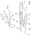
- Figure 1 we can see a device according to the invention comprising a first work station, or milling station (1) a transfer system (2) from machined cards, a second work station, or station insert (3).
- the milling station (1) has at least one magazine (11) for non-machined cards, three belts mutually parallel, namely an entry belt (12), a secondary belt (13) and a outlet (14), and a means of referencing and machining (15).
- the station card transfer system (1) at station (3) includes a first conveyor (21) to extendable flat belt (22) pivotally mounted in a vertical plane at one of its ends around an axis horizontal (16) integral with the post (1) and comprising the other end a slide (23), not shown on the figure, sliding on a metal rod and provided with its base with a roller (24) and at one of its ends with a horizontal axis (25) on which is pivotally mounted a second conveyor (26) constantly horizontal and mobile in vertical translation and mounted at its end on a linear guide system (31) which gives it a constant positioning in the vertical plane, arranged in manhole of a buffer store (32) which allows the absorption of differences in instantaneous rates from station to station the other, the assembly of the two conveyors being movable in height so that it can be adjusted according to the level of cards in the store (32).
- the system includes two slides (23; 294) each comprising at its base a roller, respectively (292) and (293), in free rotation.
- a tension spring (298) is fixed on the one hand to one of its ends on the slide (23) and the other share at the other end on the axis (16), and the slide (294) is pivotally mounted around the axis (25) at its end opposite to that opposite the slide (23).
- the two slides (23) and (294) are connected between them by the belt (22) stretched in S around the two rollers (292) and (293).
- the distance between the two rollers (292, 293) must vary to compensate for the gain in length between the two axes (16, 25), which is achievable thanks to the two slides (23, 294) which can move in translation on a rod metallic (296), parallel to the upper face of the conveyor (21), using ball guides (297, 299) by pulling on the spring (298) which plays the role of belt buffer reserve (22).
- FIGs 3a and 3b are shown a pulley (300), destacker (301), secondary belt (302), cards (303), cleats (304), a pulley (305), an input belt (306), an elevator (307), a pulley (308), a pulley (311), a descender (312), a pulley (313), an output belt (314) and a pulley (315).
- the pulleys (300) and (308) carry the belt input (306), the pulleys (305) and (313) carry the output belt (314).
- the pulleys (300, 305, 308, 311, 313, 315) of known type, for example with teeth, are parallel to each other and driven by motors, not represented.
- the belts (302, 306, 314) are parallel to each other, are notched and bear cleats (304). Motors do not drive simultaneously the pulleys, nor with identical steps. The mode of operation of these motors is presented below, in Figure 3b.
- the destacker (301), of which only the store is shown, is of known type and suitable for placing a one the cards kept in his store between two successive tabs (304) of the input belt (306).
- the cards (303) are made of plastic and known type.
- the cleats (304), presented opposite Figures 4a and 4b are suitable for holding the cards (303) during their movement.
- the elevator (307) is adapted to transfer several cards (303) simultaneously from their position between the tabs (304) of the input belt (306) at an identical position between the tabs (304) of the secondary belt (302).
- the descender (312) is adapted to transfer several maps simultaneously of their position between the tabs (304) of the secondary belt (302) at one identical position between the tabs (304) of the belt outlet (314).
- FIGS. 5a and 5b means of referencing (309) and machining means (310), which are presented with reference to FIGS. 5a and 5b.
- Ways referencing (309) are stationary.
- Ways machining (310) are only mobile simultaneously, in a plane parallel to the cards (303) for their positioning above the cavity to be machined, and according to an axis perpendicular to the cards (303) for milling cavities.
- the device according to the invention operates according to the following sequencing:
- the destacker (301) positions a card (303) between the tabs (304) of the input belt (306) at each step of the input belt (306), this step being equal to the distance between two successive couples of cleats (304).
- the secondary belt (302) advances with steps double the length of the input belt (306), in such a way that two non-machined cards are presented simultaneously before the means of referencing (309) and the machining means (310). These two cards are referenced simultaneously by the means referencing (309) and are machined simultaneously by the machining means (310) then moved simultaneously in the descender (312).
- the destacker (301), the input belt (306), the elevator (307) and the secondary belt (302) are a means of presenting two cards (303) in front of the referencing means (309)
- the descender (312) transfers them simultaneously on the output belt (314) which advances according to the same timing and the same steps as the input belt (306).
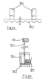
- FIG. 4a In Figure 4a are shown two tabs (304) placed on the secondary belt (302) and in the FIG. 4b the secondary belt (302), a cleat (304), a rail (316), a card (303) and a means of lower referencing (317).
- the cleats (304) have a general "L" shape whose long side is opposite to its support on the secondary belt (302).
- the rail (316) encloses at its upper part the card (303), which is in lateral support on two tabs (304) successive.
- the means of referencing lower (317) serves to support the card (303). during displacements of the secondary belt (302), the rail (316) and the lower referencing means (317) are immobile.
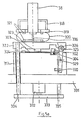
- Figure 5a are shown a pin (38), a cylindrical cavity (318), a support bellows (319), a bellows (320), washers (321), a blank press (322), a lateral referencing means fixed (323), a stop (324), a referencing means lower (317), a card (303), the secondary belt (302), a cleat (304), a movable beam (325), a wheel (326), an axis of rotation (329), a spring (330), a support (331), a clamping cylinder (332), a piece of connection (333), two sliding pins (334, 335).
- the spindle (38), the cylindrical cavity (318), the bellows support (319), the bellows (320) and the washers (321) each have a symmetry of revolution and are co-axial.
- the washers (321) link the bellows (320) of a part to the bellows support (319) and secondly to the blank press (322).
- the sliding axes (334) and (335) link rigidly the blank holder (322) and the workpiece connection (333) and slide in the means of lower referencing (317).
- the connecting piece (333) connects the head of the jack (332) to the sliding axes (334, 335).
- the spindle (38) is of known type and carries a strawberry (336). It is motionless vertically and horizontally.
- the cavity (318) carries a connection not shown. Aspiration through cavity (318) allows both cooling of the spindle (38) as the suction of the machining chips.
- the bellows support (319) is adapted to leave pass the air between the bellows (320) and the cavity (318).
- the bellows (320), made of flexible material, allows the spindle (38) to be moved independently of the movement of the blank press (322).
- the washers (321) are suitable for fixing sealingly the bellows (320) on the one hand on the bellows support (319) and on the other hand on the blank holder (322).
- the blank press (322) has notches adapted to allow the stopper (324), the belt to penetrate secondary (302) and the cleat (304).
- the blank press (322) comprises, opposite the wheel (326) a rolling face oblique, so that when the wheel (326) protrudes on the upper part of the blank press (322), it is placed more to the left than when it exceeds not.
- the fixed lateral referencing means (323) is presented opposite Figure 5b.
- the stop (324) is fixed on the means of lower referencing (317) which includes notches for the passage of the cleat (304), the secondary belt (302) and spring (330), and door the axis of rotation (329).
- the movable spar (325) carries, in its part upper, the axis of rotation of the wheel (326). It is movable around the axis of rotation (329) and receives, on its lower part, one of the supports of the spring (330). he further carries a mobile referencing means (337), visible in Figure 5b; made up of a plate perpendicular to the spar axis, plate adapted to press on the secondary belt (302).
- the spring (330) works in compression between a notch of the lower referencing means (317) and the movable spar (325).
- the support (319) carries two identical sets such as that presented in FIGS. 5a and 5b.
- the clamping cylinder (332) is of known type. His extension causes the blank holder (322) to be tightened against the card (303), the rotation of the wheel (326) on the face of the blank presser (322) and its displacement towards the left and the support of the mobile SEO (337) on the secondary belt (302).
- the fixed lateral referencing means (323) is attached to the blank press (322), as well as the axis of rotation (329).
- the means of mobile lateral referencing (337) moves by squeezing the card (303) against the lateral referencing means fixed (323).
- the extension of the clamping cylinder (332) allows thus the timing of the card (303) and its blocking in a position permanently referenced.
- the pin (38) is moved to the card (303) and the cutter (336) performs a milling intended to receive a component electronic.
- the fixed referencing means are made up the lower referencing means (317), the stop (324) and fixed lateral referencing means (323).
- Mobile SEO means are consisting of the spar (325), the referencing means movable side (337) and the blank press (322). They are adapted to clamp the cards (303) against the means of fixed referencing.
- the machining means consist of spindles (38) and strawberries (336).
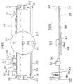
- Figure 6a are shown a pulley (300), a destacker (301), cards (303) bearing milling (338), cleats (304), a means of transport of cards (339), a positioning means (340), a pulley (315), a means of applying glue (341), a means of positioning (342) associated with the adhesive application means (341), a reduction motor (343) carrying an output axis (34), a means of transport (344) of integrated circuits (345), a gripping means (346), a rotating means (347), a pressure medium (348) and a gear motor (349) carrying an output axis (35).
- the pulleys (300) and (315) carry the means of transport of cards (339) and are of known type, by example with teeth parallel to each other and driven by engines.
- the card transport means (339) is, by example, a toothed belt.
- the means of transport (339) and (344) move along parallel axes, respectively the maps (303) and integrated circuits (345).
- the positioning means is presented opposite Figures 7a and 7b.
- the glue laying means (341) is of the type known. It has an arm and is suitable for placing in milling (338) constant quantities of glue. he is associated with identical positioning means (342) by means of positioning (340).
- the two geared motors (343, 349) are identical and together give by means of transport (344) a movement of smaller amplitude than that of the means of transport (339), but so synchronized. They respectively carry the slow axes (34, 35) and fast axes, not shown, connected to the means of transporting cards (339).
- Means of transport of integrated circuits (344) is preferably made of plastic provided training slots.
- the gripping means (346) is adapted to position a circuit on the rotation means (347) integrated (345) which it takes from the means of transport (344). It is of known type comprising, for example, a actuator pushing on the integrated circuit from bottom to top and a suction head holding the circuit integrated (345) during the rotation of the rotation means (347), tangent to the means of transport (339, 344), and suitable for presenting in front of the positioning means (340) the integrated circuits (345) supplied to it by the gripping means (346).
- the gripping means (346) is therefore on the tangent of the means of rotation (347) and the means of transportation (344).
- the positioning means (340) is at the tangent of the rotation means (347) and the means of transport (339).
- the means for applying glue (341) is upstream from the means for positioning (340) and the pressure means (348) in downstream of the same positioning means (340).
- the positioning means (340) is adapted to present the card (303) opposite the integrated circuit presented by the rotation means (347).
- the pressure means (348) is adapted to perform pressure on the integrated circuits on the cards (303) at the outlet of the positioning means (340) for a period longer than the drying time or adhesive polymerization. It is of known type, by example consisting of a suitable spacer slide.
- the device according to the invention operates according to the following sequencing:
- the destacker (301) positions a card (303) between the cleats (304 of the means of transport (339) at each of his steps. This step is equal to the distance between two successive sets of two cleats.
- the card transport (339) presents a card (303) in front of the installation means glue (341) associated with the positioning means (342), in front of the positioning means (340), at the inlet and pressure medium outlet (348).
- the means of transport (344) has an integrated circuit (345) in front of the means of gripping (346), the rotation means (347) performs a rotates half a turn and has an integrated circuit in front of the positioning means (340), the laying means glue (341) deposits a predetermined amount of glue in the milling (338) of a card (303), the means of positioning (340) allowing the positioning of a integrated circuit in a milling (338) coated with glue.
- Each card (303) therefore receives successively, at during the movement of the means of transport (339), a glue dose, an integrated circuit (345) and a pressure on this circuit (345).
- optical, electrical, magnetic or physical control cards (303) can be combined with the device presented in Figures 6a and 6b, these systems then being positioned according to their function.
- testing an integrated circuit before the positioning on the map (303) can be placed on the means of transport (344) or on the means of rotation (347).
- the electrical test of the cards (303) can be placed on the output of the device.
- the cheking process optical dimensional characteristics of the card (303) can be placed upstream of the adhesive application means (341).
- the means of transport of integrated circuits (345) carries two rows of circuits integrated (345).
- the means of transportation (344) takes half the steps of the means of transportation (339) and the gripping means (346) is adapted to take the integrated circuits (345) on the two rows.
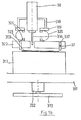
- figure 7a we can see the way of transport (339) carrying the tabs (304), a card (303) carrying a milling (338) and a support (351), by example in metal, comprising two grooves (352), 353), two pins (354, 355) located in the grooves (352, 353).
- the two grooves (352, 353) have shapes in arc of a circle and their minimum spacing is slightly less than the length of a card (303). Their width is constant on the arc of a circle.
- the groove (352), placed to the left of the map (303), has a center of an arc on its right.
- the upper parts of grooves (352; 353) greatly exceed the height of the map (303).
- the lower parts of the grooves (352, 353) form tangents of the maps (303).
- the pins (354, 355) are cylindrical in shape and have a diameter slightly smaller than the width of the grooves (352, 353). They are driven by mechanical systems, not shown, suitable for move up and down in the grooves (352, 353, according to the arcs of a circle.
- the pins (354, 355) are in the upper part grooves (352, 353) during movement of the means transport (339) and cards (303). Way to transport (339) stops approximately in the position described in Figure 7a. The pins (354, 355) are then moved to the lower part of the grooves (352, 353) and laterally block the card (303) in a perfectly referenced position.
- Figure 7b corresponds to the section of the figure 7a, along a plane passing through the axes of the pins (354, 355).
- a card (303) with a milling (338), the support (351), the grooves (352, 353) and the lugs (354, 355) we see a card (303) with a milling (338), the support (351), the grooves (352, 353) and the lugs (354, 355).
Landscapes
- Engineering & Computer Science (AREA)
- Computer Hardware Design (AREA)
- Microelectronics & Electronic Packaging (AREA)
- Physics & Mathematics (AREA)
- General Physics & Mathematics (AREA)
- Theoretical Computer Science (AREA)
- Credit Cards Or The Like (AREA)
- Delivering By Means Of Belts And Rollers (AREA)
- Supply And Installment Of Electrical Components (AREA)
- Laminated Bodies (AREA)
- Shaping Of Tube Ends By Bending Or Straightening (AREA)
- Crystals, And After-Treatments Of Crystals (AREA)
Description
- la figure 1 représente une vue schématique latérale d'un dispositif selon l'invention ;
- la figure 2a représente une vue latérale du convoyeur extensible ;
- la figure 2b représente une vue de détail du système de guidage du convoyeur extensible ;
- la figure 3a représente une vue de dessus du poste de fraisage d'un dispositif selon l'invention ;
- la figure 3b représente une vue latérale détaillée d'un taquet du même poste de fraisage ;
- la figure 4a représente une vue de dessus détaillée d'un taquet du même poste de fraisage ;
- la figure 4b représente une vue de détail latérale du taquet présenté à la figure 4a ;
- la figure 5a représente une vue de détail latérale d'un moyen de référencement et d'un moyen d'usinage ;
- la figure 5b représente une vue de détail latérale des mêmes moyens de référencement et d'usinage ;
- la figure 6a représente une vue latérale en coupe du poste d'encartage d'un dispositif selon l'invention ;
- la figure 6b représente une vue de dessus du même poste d'encartage
- la figure 7a représente une vue de détail, vue de dessus, d'un moyen de positionnement ;
- la figure 7b représente une vue de détail, latérale et en coupe, du même moyen de positionnement.
Claims (12)
- Dispositif de fabrication de cartes à puces, comportant un poste de fraisage (1) d'alvéoles dans des lots de cartes en matière plastique associé à un poste d'encartage (3) de circuits intégrés dans les dites alvéoles, caractérisé en ce que les dites cartes fraisées sont convoyées du poste de fraisage (1) au poste d'encartage (3) par un système de transfert (2) permettant une adaptation aux différences de cadence des postes (1, 3) et aux différences de positionnement des cartes sur ces postes (1, 3), les cartes fraisées étant convoyées par le système de transfert (2) du poste de fraisage vers un magasin (32) tampon du poste d'encartage (3) absorbant les différences de cadence instantanée d'un poste à l'autre, le système de transfert (2) comportant un ensemble de deux convoyeurs, un premier convoyeur horizontal (26) à hauteur variable pour la mise en place des cartes (303) dans le magasin (32) du poste d'encartage (3) en fonction du niveau de ces cartes (303) dans le magasin (32) et un second convoyeur(21) à courroie plate extensible (22) pour remédier aux différences de longueur dues aux différences de positions du convoyeur horizontal (26).
- Dispositif de fabrication selon la revendication 1, caractérisé en ce que le poste de fraisage comporte un moyen de présentation d'au moins deux cartes (303) sur un support plan devant autant de moyens de référencement fixes qu'il y a de cartes présentées simultanément par le moyen de présentation et autant de moyens d'usinage (310) qu'il y a de cartes présentées simultanément par le moyen de présentation et autant de moyens d'usinage étant mobiles en translation horizontale dans un plan parallèle à celui du support des cartes (303) et, une fois positionnés au-dessus de la zone de fraisage, mobiles en translation verticale.
- Dispositif de fabrication selon la revendication 1 ou 2, caractérisé en ce que le poste d'encartage comporte un moyen de transport de cartes (339) et un moyen de transport (344) de circuits intégrés (345), lesdits moyens de transport (339, 344) se déplaçant selon des axes parallèles ; un moyen de rotation (347) entre les moyens de transport (339, 344) ; un moyen de préhension (346) des circuits intégrés (345) acheminés sur film, ledit moyen de préhension (346) étant placé sur la tangente du moyen de transport (344) des circuits intégrés (345) et du moyen de rotation (347) ; un moyen de positionnement (340) des circuits intégrés (345) dans les logements fraisés des cartes (303), ledit moyen de positionnement (340) étant positionné à la tangente du moyen de rotation (347) et du moyen de transport de cartes (339) ; un moyen de pose de colle (341) dans las logements fraisées positionné sur le moyen de transport des cartes (339) en amont du moyen de positionnement (340) ; et un moyen de pression (348) sur les circuits intégrés (345) positionné sur le moyen de transport des cartes (339) en aval du moyen de positionnement (340).
- Dispositif selon une des revendications 1 à 3, caractérisé en ce que le moyen de présentation du poste d'usinage (1) comprend un dépileur (301), une courroie secondaire (302), le dépileur (301) transférant les cartes (303) de la courroie d'entrée (306) et une courroie secondaire (302), laquelle effectue des pas autant de fois plus grands que les pas de la courroie d'entrée (306) qu'il y a de cartes transférées simultanément par l'ascenseur (307).
- Dispositif selon la revendication 4, caractérisé en ce qu'il comporte une courroie de sortie (314) et un descenseur (312) transférant simultanément, de la courroie secondaire (302) à la courroie de sortie (306), autant de cartes que l'ascenseur (307).
- Dispositif selon la revendication 4 ou 5, caractérisé en ce que les courroies (302, 306, 314) portent des taquets (304) destinés au maintien des cartes (303).
- Dispositif selon une des revendications 4 à 6, caractérisé en ce qu'il comporte en outre des moyens de référencement mobiles (317, 337) adaptés à serrer les cartes (303) contre les moyens de référencement fixes (309, 323).
- Dispositif selon la revendication 1, caractérisé en ce que le moyen de préhension (346) du poste d'encartage (3) comporte un moyen de pression et un moyen d'aspiration.
- Dispositif selon la revendication 1 ou 8, caractérisé en ce que le moyen de positionnement (340) comporte des ergots (354, 255) mobiles dans des rainures (352, 353) en arc de cercle.
- Dispositif selon une des revendication 1, 8, 9, caractérisé en ce que le moyen de pose de colle (341) est associé à un moyen de positionnement (342).
- Dispositif selon une des revendication 1, 8, 9 ou 10, caractérisé en ce que le moyen de transport de cartes (339) est constitué d'une courroie crantée munie de taquets (304).
- Dispositif selon une des revendication 1, 8, 9, 10, 11, caractérisé en ce que les moyens de transport(339, 344) sont reliés par au moins un motoréducteur (343, 349) synchronisant leurs déplacements.
Applications Claiming Priority (2)
| Application Number | Priority Date | Filing Date | Title |
|---|---|---|---|
| FR9211430 | 1992-09-22 | ||
| FR9211430A FR2695854B1 (fr) | 1992-09-22 | 1992-09-22 | Dispositif de fraisage de cavités dans des cartes en matière plastique et d'encartage de circuits intégrés dans lesdites cavités. |
Publications (2)
| Publication Number | Publication Date |
|---|---|
| EP0589771A1 EP0589771A1 (fr) | 1994-03-30 |
| EP0589771B1 true EP0589771B1 (fr) | 2000-08-16 |
Family
ID=9433875
Family Applications (1)
| Application Number | Title | Priority Date | Filing Date |
|---|---|---|---|
| EP93402292A Expired - Lifetime EP0589771B1 (fr) | 1992-09-22 | 1993-09-20 | Dispositif de fabrication de cartes à puces |
Country Status (8)
| Country | Link |
|---|---|
| US (1) | US5397426A (fr) |
| EP (1) | EP0589771B1 (fr) |
| JP (1) | JPH071876A (fr) |
| KR (1) | KR100307937B1 (fr) |
| AT (1) | ATE195598T1 (fr) |
| CA (1) | CA2106498C (fr) |
| DE (1) | DE69329226T2 (fr) |
| FR (1) | FR2695854B1 (fr) |
Families Citing this family (12)
| Publication number | Priority date | Publication date | Assignee | Title |
|---|---|---|---|---|
| DE4433076A1 (de) * | 1994-09-16 | 1996-03-21 | Melzer Maschinenbau Gmbh | Werkzeugmaschine |
| FR2766945B1 (fr) | 1997-07-29 | 1999-10-29 | Leroux Gilles Sa | Machine de personnalisation a haute cadence |
| DE19750344C2 (de) * | 1997-11-13 | 2000-05-18 | Ods Landis & Gyr Gmbh & Co Kg | Verfahren zum Herstellen eines flachen Kartengrundkörpers für eine Chipkarte |
| TW426630B (en) * | 1998-05-28 | 2001-03-21 | Asahi Seiko Co Ltd | IC card processing machine |
| DE19926885A1 (de) * | 1999-06-12 | 2000-12-14 | Atlantic Zeiser Gmbh & Co | Transporteinrichtung für Informationsträger, insbesondere Karten |
| US7140540B2 (en) * | 2002-05-08 | 2006-11-28 | Lasercard Corporation | Method of making secure personal data card |
| EP1598861A1 (fr) * | 2004-05-19 | 2005-11-23 | Axalto S.A. | Méthode et système pour calibrer et contrôler l'implantation d'une puce dans une carte à puce |
| FR2883503B1 (fr) | 2005-03-23 | 2020-11-06 | Datacard Corp | Machine de marquage laser a haute cadence |
| FR2925969B1 (fr) * | 2007-12-26 | 2010-01-22 | Datacard Corp | Procede et dispositif d'encartage d'un module ou puce. |
| FR2939421B1 (fr) | 2008-12-05 | 2011-01-14 | Datacard Corp | Dispositif ascenseur pour machine de personnalisation et machine de personnalisation munie d'un dispositif ascenseur |
| WO2013078610A1 (fr) * | 2011-11-29 | 2013-06-06 | Gemalto Technologies (Shanghai) Co., Ltd. | Convoyeur modulaire pour l'acheminement de cartes à puce |
| DE102018004849A1 (de) * | 2017-09-29 | 2019-04-04 | J.H. Tönnjes Gmbh | Verfahren und Vorrichtung zum Versehen eines Kennzeichens, vorzugsweise eines Kraftfahrzeug-Kennzeichens, mit einem Datenträger |
Family Cites Families (13)
| Publication number | Priority date | Publication date | Assignee | Title |
|---|---|---|---|---|
| US3655024A (en) * | 1970-05-22 | 1972-04-11 | Chas H Stehling Co | Method of and apparatus for feeding workpieces to two machine units |
| US3687276A (en) * | 1971-01-04 | 1972-08-29 | Mechtron Intern Corp | Self-propelled conveyor apparatus |
| US4653630A (en) * | 1981-11-16 | 1987-03-31 | Anna Bravin | Method of and device for controlling the transfer of articles from a first conveyor belt to predetermined locations on a second conveyor belt |
| US4915565A (en) * | 1984-03-22 | 1990-04-10 | Sgs-Thomson Microelectronics, Inc. | Manipulation and handling of integrated circuit dice |
| DE3509802A1 (de) * | 1985-03-19 | 1986-09-25 | Heckler & Koch Gmbh, 7238 Oberndorf | Verfahren und vorrichtung zum handhaben von werkstuecken |
| FR2579799B1 (fr) * | 1985-03-28 | 1990-06-22 | Flonic Sa | Procede de fabrication de cartes a memoire electronique et cartes obtenues suivant ledit procede |
| CN85100044B (zh) * | 1985-04-01 | 1985-09-10 | 清华大学 | 深水池式供热堆 |
| DE3520732A1 (de) * | 1985-06-10 | 1986-12-11 | Patent-Treuhand-Gesellschaft für elektrische Glühlampen mbH, 8000 München | Montagemaschine |
| JPS626476A (ja) * | 1985-07-02 | 1987-01-13 | Kasei Baabeitamu Kk | 補強リング貼付け装置 |
| CH672285A5 (fr) * | 1987-04-14 | 1989-11-15 | Landis & Gyr Ag | |
| FR2624999B1 (fr) * | 1987-12-22 | 1990-04-06 | Sgs Thomson Microelectronics | Procede de fabrication de cartes a puce |
| US5145548A (en) * | 1989-09-16 | 1992-09-08 | Natec Incorporated | Laminating device for use in laminating a continuous id card material |
| US5097939A (en) * | 1989-11-03 | 1992-03-24 | Shanklin Corporation | Synchronous position product feed system |
-
1992
- 1992-09-22 FR FR9211430A patent/FR2695854B1/fr not_active Expired - Fee Related
-
1993
- 1993-09-20 EP EP93402292A patent/EP0589771B1/fr not_active Expired - Lifetime
- 1993-09-20 AT AT93402292T patent/ATE195598T1/de active
- 1993-09-20 CA CA002106498A patent/CA2106498C/fr not_active Expired - Fee Related
- 1993-09-20 DE DE69329226T patent/DE69329226T2/de not_active Expired - Fee Related
- 1993-09-21 KR KR1019930019434A patent/KR100307937B1/ko not_active Expired - Fee Related
- 1993-09-22 US US08/124,588 patent/US5397426A/en not_active Expired - Lifetime
- 1993-09-22 JP JP5236460A patent/JPH071876A/ja active Pending
Also Published As
| Publication number | Publication date |
|---|---|
| ATE195598T1 (de) | 2000-09-15 |
| FR2695854B1 (fr) | 1994-12-09 |
| CA2106498C (fr) | 2004-08-03 |
| KR940008550A (ko) | 1994-04-29 |
| CA2106498A1 (fr) | 1994-03-23 |
| US5397426A (en) | 1995-03-14 |
| KR100307937B1 (ko) | 2001-11-30 |
| JPH071876A (ja) | 1995-01-06 |
| FR2695854A1 (fr) | 1994-03-25 |
| DE69329226D1 (de) | 2000-09-21 |
| EP0589771A1 (fr) | 1994-03-30 |
| DE69329226T2 (de) | 2001-02-22 |
Similar Documents
| Publication | Publication Date | Title |
|---|---|---|
| CA2106498C (fr) | Dispositif de fabrication de cartes a puces | |
| EP0369133B1 (fr) | Dispositif de transfert et d'orientation d'objets plats disposés en paquets | |
| FR2475446A1 (fr) | Machine automatique de meulage de lentilles | |
| EP0248700B1 (fr) | Machine d'encaissage pour caisses américaines | |
| EP2051918B1 (fr) | Dispositif de retournement de récipients | |
| FR2656666A1 (fr) | Dispositif de transfert a va-et-vient. | |
| FR2656252A1 (fr) | Appareil et procede pour presser ensemble des feuilles superposees pour former un produit feuillete tel un pare-brise. | |
| FR2746681A1 (fr) | Procede et appareil d'alimentation en pieces longues | |
| CA2452060C (fr) | Dispositif de transport de pieces pour l'alimentation de machines | |
| FR2476399A1 (fr) | Machine pour faconner les conducteurs de composants electroniques | |
| FR2826350A1 (fr) | Dispositif de transfert de supports de pile et machine d'impression comportant un tel dispositif | |
| EP0223683B2 (fr) | Installation pour l'assemblage et/ou l'usinage de pièces portées par des palettes et palette faisant partie de cette installation | |
| FR2932717A1 (fr) | Machine a imprimer. | |
| FR2575437A1 (fr) | Machine de pose de manchons autour d'objets poses a plat | |
| FR2484969A1 (fr) | Mecanisme de stabilisation des plateaux d'un elevateur, notamment dans un systeme de transport de pieces a usiner | |
| FR2627120A1 (fr) | Machine-transfert a plateaux tournants | |
| FR2476059A1 (fr) | Machine et procede pour conformer le bord d'une plaque de verre | |
| EP0015850B1 (fr) | Dispositif de transfert de petites pièces | |
| CH624912A5 (fr) | ||
| FR2694715A1 (fr) | Procédé et appareil de rectification des manetons de villebrequin. | |
| FR2473986A1 (fr) | Installation destinee a modifier l'ecartement d'articles disposes suivant une file, notamment d'articles de confiserie a empaqueter ou a emballer | |
| FR2490532A1 (fr) | Dispositif destine a arrondir les coins de plaques de verre | |
| FR2834704A1 (fr) | Distributeur de supports individuels pour carrosseries de vehicules | |
| FR2561152A1 (fr) | Dispositif pour le transport de pieces vers une machine-outil et hors de celle-ci notamment pour l'usinage de roues dentees | |
| WO2001074511A1 (fr) | Centre de poinçonnage, destine notamment au poinçonnage de toles |
Legal Events
| Date | Code | Title | Description |
|---|---|---|---|
| PUAI | Public reference made under article 153(3) epc to a published international application that has entered the european phase |
Free format text: ORIGINAL CODE: 0009012 |
|
| AK | Designated contracting states |
Kind code of ref document: A1 Designated state(s): AT BE CH DE ES FR GB IT LI MC |
|
| 17P | Request for examination filed |
Effective date: 19941103 |
|
| 17Q | First examination report despatched |
Effective date: 19970416 |
|
| GRAG | Despatch of communication of intention to grant |
Free format text: ORIGINAL CODE: EPIDOS AGRA |
|
| GRAG | Despatch of communication of intention to grant |
Free format text: ORIGINAL CODE: EPIDOS AGRA |
|
| GRAH | Despatch of communication of intention to grant a patent |
Free format text: ORIGINAL CODE: EPIDOS IGRA |
|
| GRAH | Despatch of communication of intention to grant a patent |
Free format text: ORIGINAL CODE: EPIDOS IGRA |
|
| GRAA | (expected) grant |
Free format text: ORIGINAL CODE: 0009210 |
|
| AK | Designated contracting states |
Kind code of ref document: B1 Designated state(s): AT BE CH DE ES FR GB IT LI MC |
|
| PG25 | Lapsed in a contracting state [announced via postgrant information from national office to epo] |
Ref country code: ES Free format text: THE PATENT HAS BEEN ANNULLED BY A DECISION OF A NATIONAL AUTHORITY Effective date: 20000816 Ref country code: AT Free format text: LAPSE BECAUSE OF FAILURE TO SUBMIT A TRANSLATION OF THE DESCRIPTION OR TO PAY THE FEE WITHIN THE PRESCRIBED TIME-LIMIT Effective date: 20000816 |
|
| REF | Corresponds to: |
Ref document number: 195598 Country of ref document: AT Date of ref document: 20000915 Kind code of ref document: T |
|
| REG | Reference to a national code |
Ref country code: CH Ref legal event code: EP |
|
| REF | Corresponds to: |
Ref document number: 69329226 Country of ref document: DE Date of ref document: 20000921 |
|
| PG25 | Lapsed in a contracting state [announced via postgrant information from national office to epo] |
Ref country code: LI Free format text: LAPSE BECAUSE OF NON-PAYMENT OF DUE FEES Effective date: 20000930 Ref country code: CH Free format text: LAPSE BECAUSE OF NON-PAYMENT OF DUE FEES Effective date: 20000930 Ref country code: BE Free format text: LAPSE BECAUSE OF NON-PAYMENT OF DUE FEES Effective date: 20000930 |
|
| PG25 | Lapsed in a contracting state [announced via postgrant information from national office to epo] |
Ref country code: MC Free format text: THE PATENT HAS BEEN ANNULLED BY A DECISION OF A NATIONAL AUTHORITY Effective date: 20001016 |
|
| ITF | It: translation for a ep patent filed | ||
| GBT | Gb: translation of ep patent filed (gb section 77(6)(a)/1977) |
Effective date: 20001030 |
|
| BERE | Be: lapsed |
Owner name: S.A. GILLES LEROUX Effective date: 20000930 |
|
| REG | Reference to a national code |
Ref country code: CH Ref legal event code: PL |
|
| PLBE | No opposition filed within time limit |
Free format text: ORIGINAL CODE: 0009261 |
|
| STAA | Information on the status of an ep patent application or granted ep patent |
Free format text: STATUS: NO OPPOSITION FILED WITHIN TIME LIMIT |
|
| 26N | No opposition filed | ||
| REG | Reference to a national code |
Ref country code: GB Ref legal event code: IF02 |
|
| REG | Reference to a national code |
Ref country code: GB Ref legal event code: 732E |
|
| PGFP | Annual fee paid to national office [announced via postgrant information from national office to epo] |
Ref country code: DE Payment date: 20070918 Year of fee payment: 15 |
|
| PGFP | Annual fee paid to national office [announced via postgrant information from national office to epo] |
Ref country code: GB Payment date: 20070823 Year of fee payment: 15 |
|
| PGFP | Annual fee paid to national office [announced via postgrant information from national office to epo] |
Ref country code: IT Payment date: 20070912 Year of fee payment: 15 |
|
| PGFP | Annual fee paid to national office [announced via postgrant information from national office to epo] |
Ref country code: FR Payment date: 20071001 Year of fee payment: 15 |
|
| GBPC | Gb: european patent ceased through non-payment of renewal fee |
Effective date: 20080920 |
|
| REG | Reference to a national code |
Ref country code: FR Ref legal event code: ST Effective date: 20090529 |
|
| PG25 | Lapsed in a contracting state [announced via postgrant information from national office to epo] |
Ref country code: IT Free format text: LAPSE BECAUSE OF NON-PAYMENT OF DUE FEES Effective date: 20080920 Ref country code: DE Free format text: LAPSE BECAUSE OF NON-PAYMENT OF DUE FEES Effective date: 20090401 |
|
| PG25 | Lapsed in a contracting state [announced via postgrant information from national office to epo] |
Ref country code: FR Free format text: LAPSE BECAUSE OF NON-PAYMENT OF DUE FEES Effective date: 20080930 |
|
| PG25 | Lapsed in a contracting state [announced via postgrant information from national office to epo] |
Ref country code: GB Free format text: LAPSE BECAUSE OF NON-PAYMENT OF DUE FEES Effective date: 20080920 |