US5397426A - Device for producing smart cards - Google Patents

Device for producing smart cards Download PDF

Info

Publication number
US5397426A
US5397426A US08/124,588 US12458893A US5397426A US 5397426 A US5397426 A US 5397426A US 12458893 A US12458893 A US 12458893A US 5397426 A US5397426 A US 5397426A
Authority
US
United States
Prior art keywords
cards
conveying
integrated circuits
belt
station
Prior art date
Legal status (The legal status is an assumption and is not a legal conclusion. Google has not performed a legal analysis and makes no representation as to the accuracy of the status listed.)
Expired - Lifetime
Application number
US08/124,588
Inventor
Gerard Nioche
Dominique Perdoux
Patrick Baudron
Current Assignee (The listed assignees may be inaccurate. Google has not performed a legal analysis and makes no representation or warranty as to the accuracy of the list.)
GILLIES LEROUX SA
Entrust Corp
Original Assignee
Gilles Leroux SA
Priority date (The priority date is an assumption and is not a legal conclusion. Google has not performed a legal analysis and makes no representation as to the accuracy of the date listed.)
Filing date
Publication date
Application filed by Gilles Leroux SA filed Critical Gilles Leroux SA
Assigned to GILLIES LEROUX S.A. reassignment GILLIES LEROUX S.A. ASSIGNMENT OF ASSIGNORS INTEREST (SEE DOCUMENT FOR DETAILS). Assignors: BAUDRON, PATRICK, NIOCHE, GERARD, PERDOUX, DOMINIQUE
Application granted granted Critical
Publication of US5397426A publication Critical patent/US5397426A/en
Assigned to DATACARD CORPORATION reassignment DATACARD CORPORATION ASSIGNMENT OF ASSIGNORS INTEREST (SEE DOCUMENT FOR DETAILS). Assignors: GILLES LEROUX S.A.
Anticipated expiration legal-status Critical
Expired - Lifetime legal-status Critical Current

Links

Images

Classifications

    • GPHYSICS
    • G06COMPUTING; CALCULATING OR COUNTING
    • G06KGRAPHICAL DATA READING; PRESENTATION OF DATA; RECORD CARRIERS; HANDLING RECORD CARRIERS
    • G06K19/00Record carriers for use with machines and with at least a part designed to carry digital markings
    • G06K19/06Record carriers for use with machines and with at least a part designed to carry digital markings characterised by the kind of the digital marking, e.g. shape, nature, code
    • G06K19/067Record carriers with conductive marks, printed circuits or semiconductor circuit elements, e.g. credit or identity cards also with resonating or responding marks without active components
    • G06K19/07Record carriers with conductive marks, printed circuits or semiconductor circuit elements, e.g. credit or identity cards also with resonating or responding marks without active components with integrated circuit chips
    • G06K19/077Constructional details, e.g. mounting of circuits in the carrier
    • G06K19/07745Mounting details of integrated circuit chips
    • GPHYSICS
    • G06COMPUTING; CALCULATING OR COUNTING
    • G06KGRAPHICAL DATA READING; PRESENTATION OF DATA; RECORD CARRIERS; HANDLING RECORD CARRIERS
    • G06K19/00Record carriers for use with machines and with at least a part designed to carry digital markings
    • G06K19/06Record carriers for use with machines and with at least a part designed to carry digital markings characterised by the kind of the digital marking, e.g. shape, nature, code
    • G06K19/067Record carriers with conductive marks, printed circuits or semiconductor circuit elements, e.g. credit or identity cards also with resonating or responding marks without active components
    • G06K19/07Record carriers with conductive marks, printed circuits or semiconductor circuit elements, e.g. credit or identity cards also with resonating or responding marks without active components with integrated circuit chips
    • G06K19/077Constructional details, e.g. mounting of circuits in the carrier
    • HELECTRICITY
    • H01ELECTRIC ELEMENTS
    • H01LSEMICONDUCTOR DEVICES NOT COVERED BY CLASS H10
    • H01L2924/00Indexing scheme for arrangements or methods for connecting or disconnecting semiconductor or solid-state bodies as covered by H01L24/00
    • H01L2924/0001Technical content checked by a classifier
    • H01L2924/0002Not covered by any one of groups H01L24/00, H01L24/00 and H01L2224/00
    • YGENERAL TAGGING OF NEW TECHNOLOGICAL DEVELOPMENTS; GENERAL TAGGING OF CROSS-SECTIONAL TECHNOLOGIES SPANNING OVER SEVERAL SECTIONS OF THE IPC; TECHNICAL SUBJECTS COVERED BY FORMER USPC CROSS-REFERENCE ART COLLECTIONS [XRACs] AND DIGESTS
    • Y10TECHNICAL SUBJECTS COVERED BY FORMER USPC
    • Y10TTECHNICAL SUBJECTS COVERED BY FORMER US CLASSIFICATION
    • Y10T156/00Adhesive bonding and miscellaneous chemical manufacture
    • Y10T156/12Surface bonding means and/or assembly means with cutting, punching, piercing, severing or tearing
    • Y10T156/1304Means making hole or aperture in part to be laminated
    • Y10T156/1309Means making hole or aperture in part to be laminated and securing separate part over hole or aperture
    • YGENERAL TAGGING OF NEW TECHNOLOGICAL DEVELOPMENTS; GENERAL TAGGING OF CROSS-SECTIONAL TECHNOLOGIES SPANNING OVER SEVERAL SECTIONS OF THE IPC; TECHNICAL SUBJECTS COVERED BY FORMER USPC CROSS-REFERENCE ART COLLECTIONS [XRACs] AND DIGESTS
    • Y10TECHNICAL SUBJECTS COVERED BY FORMER USPC
    • Y10TTECHNICAL SUBJECTS COVERED BY FORMER US CLASSIFICATION
    • Y10T156/00Adhesive bonding and miscellaneous chemical manufacture
    • Y10T156/17Surface bonding means and/or assemblymeans with work feeding or handling means
    • Y10T156/1702For plural parts or plural areas of single part
    • Y10T156/1744Means bringing discrete articles into assembled relationship
    • Y10T156/1768Means simultaneously conveying plural articles from a single source and serially presenting them to an assembly station
    • Y10T156/1771Turret or rotary drum-type conveyor
    • YGENERAL TAGGING OF NEW TECHNOLOGICAL DEVELOPMENTS; GENERAL TAGGING OF CROSS-SECTIONAL TECHNOLOGIES SPANNING OVER SEVERAL SECTIONS OF THE IPC; TECHNICAL SUBJECTS COVERED BY FORMER USPC CROSS-REFERENCE ART COLLECTIONS [XRACs] AND DIGESTS
    • Y10TECHNICAL SUBJECTS COVERED BY FORMER USPC
    • Y10TTECHNICAL SUBJECTS COVERED BY FORMER US CLASSIFICATION
    • Y10T156/00Adhesive bonding and miscellaneous chemical manufacture
    • Y10T156/17Surface bonding means and/or assemblymeans with work feeding or handling means
    • Y10T156/1702For plural parts or plural areas of single part
    • Y10T156/1744Means bringing discrete articles into assembled relationship
    • Y10T156/1776Means separating articles from bulk source
    • Y10T156/1778Stacked sheet source

Definitions

  • This invention has as its object a device that makes possible the milling of cavities in plastic cards, commonly called “smart cards,” and the inlaying of integrated circuits in said cavities.
  • Cards with microcircuits are generally polyvinyl chloride cards printed and provided with a housing in which an integrated circuit or electronic "chip" is implanted.
  • the object of this invention is to eliminate these drawbacks by proposing a machine composed of two work stations managed by an automatic system, one of which has as its main function the milling of recesses in batches of plastic cards and the other the inlaying of integrated circuits in said recesses, a connecting system making possible the transfer of the cards from the first station to the second station.
  • the device for producing smart cards is characterized in that it comprises a station for milling of recesses in batches of plastic cards associated with a station for inlaying of integrated circuits in said recesses, said milled cards being conveyed from the milling station to the inlaying station by a transfer system that makes possible an adaptation to the speed differences of the stations and to the positioning differences of these stations.
  • the milling station comprises a means for presenting at least two cards on a plane support in front of as many stationary referencing means as there are cards presented simultaneously by the presentation means and as many machining means as there are cards presented simultaneously by the presentation means, said means for machinings being mobile in horizontal translation in a plane parallel to that of the support of the cards and, once positioned above the milling zone, mobile in vertical translation.
  • the inlaying station comprises a means for conveying cards and a means for conveying integrated circuits, said conveying means being displaced along parallel axes; a means for rotation between the conveying means; a means for grasping the integrated circuits routed on film, said grasping means being placed on the tangent of the means for conveying the integrated circuits and of the rotation means; a means for positioning the integrated circuits in the milled housings of the cards, said positioning means being positioned on the tangent of the rotation means and of the means for conveying cards; a means for placing glue in the milled housings positioned on the means for conveying the cards upstream from the positioning means; and a means for pressure on the integrated circuits positioned on the means for conveying the cards downstream from the positioning means.
  • the transfer device comprises two conveyors, a horizontal conveyor with variable height for the placing of the cards in the magazine of the inlaying station and a conveyor with an extendable flat belt to take care of the differences in length due to the differences of positions of the horizontal conveyor.
  • This characteristic arrangement makes it possible to machine simultaneously and to inlay the cards with a great precision and in a reduced space.
  • FIG. 1 represents a lateral diagrammatic view of a device according to the invention
  • FIG. 2a represents a lateral view of the extendable conveyor
  • FIG. 2b represents a detail view of the guiding system of the extendable conveyor
  • FIG. 3a represents a top view of the milling station of a device according to the invention.
  • FIG. 3b represents a lateral view of the same milling station
  • FIG. 4a represents a detailed top view of a catch of the same milling station
  • FIG. 4b represents a lateral detail view of the catch shown in FIG. 4a;
  • FIG. 5a represents a lateral detail view of a referencing means and of a machining means
  • FIG. 5b represents a lateral detail view of the same referencing and machining means
  • FIG. 6a represents a lateral view in section of the inlaying station of a device according to the invention.
  • FIG. 6b represents a top view of the same inlaying station
  • FIG. 7a represents a detail view, seen from above, of a positioning means
  • FIG. 7b represents a detail view, lateral and in section, of the same positioning means.
  • FIG. 1 it is possible to see a device according to the invention comprising a first work station, or milling station (1), a system (2) for transfer of machined cards, a second work station, or inlaying station (3).
  • Milling station (1) comprises at least one magazine (11) with unmachined cards, three parallel belts between them, namely an input belt (12), a secondary belt (13) and an output belt (14), and a referencing and machining means (15).
  • the system for transfer of the cards from station (1) to station (3) comprises a first conveyor (21) with extendable flat belt (22) mounted to pivot in a vertical plane at one of its ends around a horizontal pin (16) integral with station (1) and comprising at the other end a guide (23), not shown in the figure, sliding on a metal rod and provided at its base with a roller (24) and at one of its ends with a horizontal pin (25) on which a second conveyor (26) is mounted to pivot that is constantly horizontal and mobile in vertical translation and mounted at its end on a linear guiding system (31) which assures it a constant positioning in the vertical plane, placed opposite a buffer magazine (32) that makes it possible to absorb the instantaneous differences in speeds from one station to the next, the two conveyors together being mobile in height so as to be able to be adjusted as a function of the level of the cards in magazine (32).
  • FIG. 2a it is possible to see a conveyor (21) that can be extended in two work positions, a horizontal position (27) and an angular position (28) in which the distance between the two pins (16) and (25) has increased in relation to the first position, driving run (22) always being in the same length, the passage from one position to the next on the same imaginary straight line represented by broken lines of pin (25) being able to be achieved thanks to a system comprising two guides, not shown, and two rollers (292, 293), this system of variation making it possible for the second conveyor (26) integral with pin (25) to remain constantly on the same vertical path and in a horizontal plane during the movement.
  • FIG. 2b it is possible to see in detail the system that makes it possible to adapt the length between the pins (16, 25) to the different positions of horizontal conveyor (26), not shown in the figure.
  • the system comprises two guides (23, 294) each comprising at its base a roller, (292) and (293) respectively, in free rotation.
  • a tension spring (298) is fastened, on the one hand, at one of its ends on guide (23) and, on the other hand, at the other end on pin (16), and guide (294) is mounted to pivot around pin (25) at its end opposite the one facing guide (23).
  • the two guides (23) and (294) are connected to one another by belt (22) stretched in an S shape around the two rollers (292) and (293).
  • the distance between the two rollers (292, 293) must vary to compensate for the gain in length between the two pins (16, 25), which can be achieved thanks to the two guides (23, 294) which can be displaced in translation on a metal rod (296), parallel to the upper face of conveyor (21), with ball guides (297, 299) by pulling on spring (298) which acts as reserve buffer for belt (22).
  • FIGS. 3a and 3b there are represented a pulley (300), an unstacker (301), a secondary belt (302), cards (303), catches (304), a pulley (305), an input belt (306), a lift (307), a pulley (308), a pulley (311), a chute (312), a pulley (313), an output belt (314) and a pulley (315).
  • Pulleys (300) and (308) carry input belt (306), pulleys (305) and (313) carry output belt (314).
  • Pulleys (300, 305, 308, 311, 313, 315) of known type, for example with teeth, are parallel to one another and driven by motors, not shown.
  • Belts (302, 306, 314) are parallel to one another, are notched and carry catches (304). The motors do not drive the pulleys simultaneously, or with identical pitches. The operating mode of these motors is presented farther below, in FIG. 3b.
  • Unstacker (301) only the magazine of which is shown, is of known type and adapted to place the cards that are kept in its magazine one by one between two successive catches (304) of input belt (306).
  • Cards (303) are plastic and of known type.
  • Catches (304), shown by a look at FIGS. 4a and 4b, are adapted to hold cards (303) during their displacement.
  • Lift (307) is adapted to transfer several cards (303) simultaneously from their position between catches (304) of input belt (306) to an identical position between catches (304) of secondary belt (302).
  • Chute (312) is adapted to transfer several cards simultaneously from their position between catches (304) of secondary belt (302) to an identical position between catches (304) of output belt (314).
  • FIG. 3b Also seen in FIG. 3b are referencing means (309) and machining means (310), which are shown by a look at FIGS. 5a and 5b.
  • Referencing means (309) have a stationary station. Machining means (310) are mobile only simultaneously, in a plane parallel to cards (303) for their positioning above the cavity to be machined, and along an axis perpendicular to cards (303) for the milling of the cavities.
  • the device according to the invention operates according to the following sequence:
  • Unstacker (301) positions a card (303) between catches (304) of input belt (306) at each step of input belt (306), this step being equal to the distance between two successive pairs of catches (304).
  • Secondary belt (302) advances with length steps double those of input belt (306), so that two unmachined cards are presented simultaneously in front of referencing means (309) and machining means (310). These two cards are simultaneously referenced by referencing means (309) and are simultaneously machined by machining means (310) then simultaneously displaced into chute (312).
  • Unstacker (301), input belt (306), lift (307) and secondary belt (302) constitute a means for presenting two cards (303) in front of referencing means (309).
  • Chute (312) transfers them simultaneously onto output belt (314) which advances at the same rate and at the same steps as input belt (306).
  • optical or physical control systems of cards (303) can be combined with the device shown in FIG. 3a and 3b. These systems will then be preferably positioned facing output belt (314).
  • FIG. 4a two catches (304) are represented that are placed on secondary belt (302) and in FIG. 4b secondary belt (302), a catch (304), a rail (316), a card (303) and a lower referencing means (317) are represented.
  • Catches (304) have a general "L" shape whose large side is located on the opposite side from its support on secondary belt (302).
  • Rail (316) at its upper part holds card (303), which is laterally resting on two successive catches (304). Finally, lower referencing means (317) serve as support for card (303). During the displacements of secondary belt (302), rail (316) and lower referencing means (317) are immobile.
  • FIG. 5a there are represented a spindle (38), a cylindrical cavity (318), a bellows support (319), a bellows (320), washers (321), a blank press (322), a stationary lateral referencing means (323), a stop (324), a lower referencing means (317), a card (303), secondary belt (302), a catch (304), a mobile beam (325), a wheel (326), an axis of rotation (329), a spring (330), a support (331), a tightening cylinder (332), a connecting part (333), two sliding pins (334, 335).
  • Washers (321) connect bellows (320) on the one hand to bellows support (319) and, on the other hand, to blank press (322).
  • Sliding pins (334) and (335) rigidly connect blank press (322) and connecting part (333) and slide in lower referencing means (317).
  • Connecting part (333) connects the head of cylinder (332) to sliding pins (334, 335).
  • Spindle (38) is of known type and carries a milling cutter (336). It is immobile vertically and horizontally.
  • Cavity (318) carries a suction connection, not shown.
  • the suction through cavity (318) makes possible both the cooling of spindle (38) and the sucking up of the machining cuttings.
  • Bellows support (319) is adapted to allow air to pass between bellows (320) and cavity (318).
  • Washers (321) are adapted to fasten, in a fluidtight manner, bellows (320) on the one hand to bellows support (319) and on the other hand to blank press (322).
  • Blank press (322) comprises indentations adapted to allow stop (324), secondary belt (302) and catch (304) to penetrate.
  • Blank press (322) comprises, opposite wheel (326) an oblique rolling face, so that when wheel (326) protrudes on the upper part of blank press (322), it is placed more to the left than when it does not protrude.
  • Stationary lateral referencing means (323) is shown by a look at FIG. 5b.
  • Stop (324) is fastened to lower referencing means (317) which comprises indentations for the passage of catch (304), of secondary belt (302) and of spring (330), and carries axis of rotation (329).
  • Mobile beam (325) carries, at its upper part, the axis of rotation of wheel (326). It is mobile around axis of rotation (329) and receives, on its lower part, one of the supports of spring (330). In addition, it carries a mobile referencing means (337), that can be seen in FIG. 5b; consisting of a plate perpendicular to the axis of the beam, a plate adapted to rest on secondary belt (302).
  • Spring (330) works in compression between an indentation of lower referencing means (317) and mobile beam (325).
  • Support (319) carries two identical units as shown in FIGS. 5a and 5b.
  • Tightening cylinder (332) is of known type. Its extension causes the tightening of blank press (322) against card (303), the rotation of wheel (326) on the rolling face of blank press (322) and its displacement to the left and the support of mobile referencing means (337) on secondary belt (302).
  • Stationary lateral referencing means (323) is fastened to blank press (322), as well as axis of rotation (329).
  • blank press (322) approaches card (303) and touches it, mobile lateral referencing means (337) is displaced while holding card (303) tightly against stationary lateral referencing means (323).
  • spindle (38) is displaced toward card (303) and milling cutter (336) performs a milling intended to receive an electronic component.
  • the stationary referencing means consist of lower referencing means (317), stop (324) and stationary lateral referencing means (323).
  • the mobile referencing means consist of beam (325), mobile lateral referencing means (337) and blank press (322). They are adapted to hold cards (303) tightly against the stationary referencing means.
  • the machining means consist of spindles (38) and milling cutters (336).
  • FIG. 6a there are represented a pulley (300), an unstacker (301), cards (303) carrying millings (338), catches (304), a means (339) for conveying cards, a positioning means (340), a pulley (315), a means (341) for placing glue, a positioning means (342) associated with means (341) for placing glue, a gearmotor (343) carrying an output pin (34), a means (344) for conveying integrated circuits (345), a grasping means (346), a rotation means (347), a pressure means (348) and a gearmotor (349) carrying an output pin (35).
  • Pulleys (300) and (315) carry means (339) for conveying cards and are of known type, for example with teeth parallel to one another and driven by motors.
  • Means (339) for conveying cards is, for example, a notched belt.
  • Conveying means (339) and (344) displace, along parallel axes, cards (303) and integrated circuits (345), respectively.
  • the positioning means is shown by a look at FIGS. 7a and 7b.
  • Means (341) for placing glue is of known type. It comprises an arm and is adapted to deposit constant amounts of glue in machinings (338). It is associated with a positioning means (342) that is identical with positioning means (340).
  • the two gearmotors (343, 349) are identical and, together, give to conveying means (344) a movement of smaller amplitude than that of conveying means (339), but in a synchronized way. They carry respectively the slow pins (34, 35) and fast pins, not shown, connected to means (339) for conveying cards.
  • Means (344) for conveying integrated circuits is preferably of plastic provided with drive notches.
  • Grasping means (346) is adapted to position on means of rotation (347) an integrated circuit (345) that it takes from conveying means (344). It is of known type comprising, for example, an actuator performing an upward thrust on the integrated circuit and a suction head holding integrated circuits (345) during the rotation of rotation means (347), tangent to conveying means (339, 344), and adapted to present, in front of positioning means (340), the integrated circuits (345) that grasping means (346) have furnished for it.
  • Grasping means (346) is therefore on the tangent of rotation means (347) and of conveying means (344). Also, positioning means (340) is on the tangent of rotation means (347) and of conveying means (339).
  • means (341) for placing glue is upstream from positioning means (340) and pressure means (348) downstream from this same positioning means (340).
  • Positioning means (340) is adapted to present card (303) opposite the integrated circuit presented by rotation means (347).
  • Pressure means (348) is adapted to perform a pressure on the integrated circuits present on cards (303) at the output of positioning means (340) during a period greater than the drying or polymerization period of the glue. It is of known type, for example consisting of a suitable separation slide mechanism.
  • the device according to the invention operates according to the following sequence:
  • Unstacker (301) positions a card (303) between catches (304) of conveying means (339) at each of its steps. This step is equal to the distance between two successive groupings of two catches.
  • means (339) for conveying cards presents a card (303) in front of means (341) for placing glue associated with positioning means (342), in front of positioning means (340), at the input and output of pressure means (348).
  • conveying means (344) presents an integrated circuit (345) in front of grasping means (346), rotation means (347) performs a rotation of a half-turn and presents an integrated circuit in front of positioning means (340), means (341) for placing glue deposits a predetermined amount of glue in the milling (338) of a card (303), positioning means (340) making possible the positioning of an integrated circuit in a milling (338) coated with glue.
  • Each card (303) therefore receives successively, during the displacement of conveying means (339), an amount of glue, an integrated circuit (345) and a pressure on this circuit (345).
  • the test of an integrated circuit before positioning on card (303) can be placed on conveying means (344) or on rotation means (347).
  • the electric test of cards (303) can be placed at the output of the device.
  • the optical checking of the dimensional characteristics of card (303) can be placed upstream from means (341) for placing glue.
  • the means for conveying integrated circuits (345) carries two rows of integrated circuits (345).
  • conveying means (344) performs two times fewer steps than conveying means (339) and grasping means (346) is adapted to take integrated circuits (345) on both rows.
  • the two grooves (352, 353) have arc shapes and their minimal spacing is slightly less than the length of a card (303). Their width is constant on the arc. Groove (352), placed on the left of card (303), has an arc center on its right. The high portions of grooves (352, 353) project widely beyond the height of card (303). The low portions of grooves (352, 353) form tangents of cards (303).
  • Lugs (354, 355) are of cylindrical shape and have a diameter slightly less than the width of grooves (352,353). They are moved by mechanical systems, not shown, adapted to displace them upward in grooves (352, 353) along the arcs.
  • Lugs (354, 355) are in the upper portion of grooves (352, 353) during the displacement of conveying means (339) and of cards (303). Conveying means (339) stops approximately in the position described in FIG. 7a. Lugs (354, 355) are then displaced to the lower portion of grooves (352, 353) and laterally lock card (303) in a perfectly referenced position.
  • FIG. 7b corresponds to the section of FIG. 7a, along a plane passing through the axes of lugs (354, 355).
  • a card (303) is seen there carrying a milling (338), support (351), grooves (352, 353) and lugs (354, 355).

Abstract

This invention relates to a device for producing smart cards, characterized in that it comprises a station (1) for milling recesses in batches of plastic cards associated with a station (3) for inlaying integrated circuits in said recesses, said milled cards being conveyed from milling station (1) to inlaying station (3) by a transfer system (2) making possible an adaptation to the speed differences of the stations (1, 3) and to the positioning differences of these stations (1, 3).

Description

This invention has as its object a device that makes possible the milling of cavities in plastic cards, commonly called "smart cards," and the inlaying of integrated circuits in said cavities.
Cards with microcircuits are generally polyvinyl chloride cards printed and provided with a housing in which an integrated circuit or electronic "chip" is implanted.
The making of these housings and the inlaying is currently performed with various devices that are distinguished by their cost, the amount of cards machined per hour and the quality of the final product.
The devices known to date, however, have a considerable bulk and can cause beads, during the placing of the glue, around the cavity provided for the positioning of the chip, and they further do not make possible a quick milling of several thousand cards per hour.
The object of this invention is to eliminate these drawbacks by proposing a machine composed of two work stations managed by an automatic system, one of which has as its main function the milling of recesses in batches of plastic cards and the other the inlaying of integrated circuits in said recesses, a connecting system making possible the transfer of the cards from the first station to the second station.
This object is attained by the fact that the device for producing smart cards is characterized in that it comprises a station for milling of recesses in batches of plastic cards associated with a station for inlaying of integrated circuits in said recesses, said milled cards being conveyed from the milling station to the inlaying station by a transfer system that makes possible an adaptation to the speed differences of the stations and to the positioning differences of these stations.
According to another feature, the milling station comprises a means for presenting at least two cards on a plane support in front of as many stationary referencing means as there are cards presented simultaneously by the presentation means and as many machining means as there are cards presented simultaneously by the presentation means, said means for machinings being mobile in horizontal translation in a plane parallel to that of the support of the cards and, once positioned above the milling zone, mobile in vertical translation.
According to another feature, the inlaying station comprises a means for conveying cards and a means for conveying integrated circuits, said conveying means being displaced along parallel axes; a means for rotation between the conveying means; a means for grasping the integrated circuits routed on film, said grasping means being placed on the tangent of the means for conveying the integrated circuits and of the rotation means; a means for positioning the integrated circuits in the milled housings of the cards, said positioning means being positioned on the tangent of the rotation means and of the means for conveying cards; a means for placing glue in the milled housings positioned on the means for conveying the cards upstream from the positioning means; and a means for pressure on the integrated circuits positioned on the means for conveying the cards downstream from the positioning means.
According to another feature, the transfer device comprises two conveyors, a horizontal conveyor with variable height for the placing of the cards in the magazine of the inlaying station and a conveyor with an extendable flat belt to take care of the differences in length due to the differences of positions of the horizontal conveyor.
This characteristic arrangement makes it possible to machine simultaneously and to inlay the cards with a great precision and in a reduced space.
The following description, made with reference to the accompanying drawings for an explanatory and in no way limiting purpose, will make it possible to understand better the advantages, objects and characteristics of this invention.
In the accompanying drawings:
FIG. 1 represents a lateral diagrammatic view of a device according to the invention;
FIG. 2a represents a lateral view of the extendable conveyor;
FIG. 2b represents a detail view of the guiding system of the extendable conveyor;
FIG. 3a represents a top view of the milling station of a device according to the invention;
FIG. 3b represents a lateral view of the same milling station;
FIG. 4a represents a detailed top view of a catch of the same milling station;
FIG. 4b represents a lateral detail view of the catch shown in FIG. 4a;
FIG. 5a represents a lateral detail view of a referencing means and of a machining means;
FIG. 5b represents a lateral detail view of the same referencing and machining means;
FIG. 6a represents a lateral view in section of the inlaying station of a device according to the invention;
FIG. 6b represents a top view of the same inlaying station
FIG. 7a represents a detail view, seen from above, of a positioning means;
FIG. 7b represents a detail view, lateral and in section, of the same positioning means.
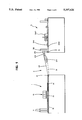
In FIG. 1, it is possible to see a device according to the invention comprising a first work station, or milling station (1), a system (2) for transfer of machined cards, a second work station, or inlaying station (3).
Milling station (1) comprises at least one magazine (11) with unmachined cards, three parallel belts between them, namely an input belt (12), a secondary belt (13) and an output belt (14), and a referencing and machining means (15).
On inlaying station (3), it is possible to see a linear guiding system (31), a buffer magazine (32), a means (341) for placing glue associated with a positioning means (342), a rotation means (347).
The system for transfer of the cards from station (1) to station (3) comprises a first conveyor (21) with extendable flat belt (22) mounted to pivot in a vertical plane at one of its ends around a horizontal pin (16) integral with station (1) and comprising at the other end a guide (23), not shown in the figure, sliding on a metal rod and provided at its base with a roller (24) and at one of its ends with a horizontal pin (25) on which a second conveyor (26) is mounted to pivot that is constantly horizontal and mobile in vertical translation and mounted at its end on a linear guiding system (31) which assures it a constant positioning in the vertical plane, placed opposite a buffer magazine (32) that makes it possible to absorb the instantaneous differences in speeds from one station to the next, the two conveyors together being mobile in height so as to be able to be adjusted as a function of the level of the cards in magazine (32).
In FIG. 2a, it is possible to see a conveyor (21) that can be extended in two work positions, a horizontal position (27) and an angular position (28) in which the distance between the two pins (16) and (25) has increased in relation to the first position, driving run (22) always being in the same length, the passage from one position to the next on the same imaginary straight line represented by broken lines of pin (25) being able to be achieved thanks to a system comprising two guides, not shown, and two rollers (292, 293), this system of variation making it possible for the second conveyor (26) integral with pin (25) to remain constantly on the same vertical path and in a horizontal plane during the movement.
In FIG. 2b, it is possible to see in detail the system that makes it possible to adapt the length between the pins (16, 25) to the different positions of horizontal conveyor (26), not shown in the figure.
The system comprises two guides (23, 294) each comprising at its base a roller, (292) and (293) respectively, in free rotation.
A tension spring (298) is fastened, on the one hand, at one of its ends on guide (23) and, on the other hand, at the other end on pin (16), and guide (294) is mounted to pivot around pin (25) at its end opposite the one facing guide (23).
The two guides (23) and (294) are connected to one another by belt (22) stretched in an S shape around the two rollers (292) and (293).
To keep the tension of belt (22) constant at any point of conveyor (21) during its passage from a position making a certain angle with the ground at a higher angle position, the distance between the two rollers (292, 293) must vary to compensate for the gain in length between the two pins (16, 25), which can be achieved thanks to the two guides (23, 294) which can be displaced in translation on a metal rod (296), parallel to the upper face of conveyor (21), with ball guides (297, 299) by pulling on spring (298) which acts as reserve buffer for belt (22).
On the other hand, when the conveyor goes from a position making a certain angle with the ground at a lower angle, the length between pins (16, 25) decreases and the belt remains taut thanks to the increase in length between rollers (292, 293) due to the force exerted by spring (298).
In FIGS. 3a and 3b there are represented a pulley (300), an unstacker (301), a secondary belt (302), cards (303), catches (304), a pulley (305), an input belt (306), a lift (307), a pulley (308), a pulley (311), a chute (312), a pulley (313), an output belt (314) and a pulley (315).
Pulleys (300) and (308) carry input belt (306), pulleys (305) and (313) carry output belt (314). Pulleys (300, 305, 308, 311, 313, 315) of known type, for example with teeth, are parallel to one another and driven by motors, not shown. Belts (302, 306, 314) are parallel to one another, are notched and carry catches (304). The motors do not drive the pulleys simultaneously, or with identical pitches. The operating mode of these motors is presented farther below, in FIG. 3b.
Unstacker (301), only the magazine of which is shown, is of known type and adapted to place the cards that are kept in its magazine one by one between two successive catches (304) of input belt (306).
Cards (303) are plastic and of known type.
Catches (304), shown by a look at FIGS. 4a and 4b, are adapted to hold cards (303) during their displacement.
Lift (307) is adapted to transfer several cards (303) simultaneously from their position between catches (304) of input belt (306) to an identical position between catches (304) of secondary belt (302).
Chute (312) is adapted to transfer several cards simultaneously from their position between catches (304) of secondary belt (302) to an identical position between catches (304) of output belt (314).
Also seen in FIG. 3b are referencing means (309) and machining means (310), which are shown by a look at FIGS. 5a and 5b. Referencing means (309) have a stationary station. Machining means (310) are mobile only simultaneously, in a plane parallel to cards (303) for their positioning above the cavity to be machined, and along an axis perpendicular to cards (303) for the milling of the cavities.
Referencing means (309) and machining means (310) act on cards (303) placed on secondary belt (302).
The device according to the invention operates according to the following sequence:
Unstacker (301) positions a card (303) between catches (304) of input belt (306) at each step of input belt (306), this step being equal to the distance between two successive pairs of catches (304).
When two cards (303) have entered-lift (307) and when two groups of two catches (304) free on secondary belt (302) are facing lift (307), the latter transfers the two cards onto secondary belt (302).
Secondary belt (302) advances with length steps double those of input belt (306), so that two unmachined cards are presented simultaneously in front of referencing means (309) and machining means (310). These two cards are simultaneously referenced by referencing means (309) and are simultaneously machined by machining means (310) then simultaneously displaced into chute (312).
Unstacker (301), input belt (306), lift (307) and secondary belt (302) constitute a means for presenting two cards (303) in front of referencing means (309).
Chute (312) transfers them simultaneously onto output belt (314) which advances at the same rate and at the same steps as input belt (306).
In FIGS. 3a and 3b, for reasons of clarity of drawing, only two cards (303) are transferred simultaneously by lift (307) or by chute (312). However, this number is preferably greater than 2 for the advantages of the invention to be best used.
For example, for the simultaneous machining of three cards (303), lift (307) and chute (312) transfer simultaneously three cards (303), three referencing means (309) are used as well as three machining means (310). The steps of the secondary belt are then triple the steps of input belt (306) and of output belt (314).
It is important to note that the optical or physical control systems of cards (303) can be combined with the device shown in FIG. 3a and 3b. These systems will then be preferably positioned facing output belt (314).
In FIG. 4a two catches (304) are represented that are placed on secondary belt (302) and in FIG. 4b secondary belt (302), a catch (304), a rail (316), a card (303) and a lower referencing means (317) are represented.
Catches (304) have a general "L" shape whose large side is located on the opposite side from its support on secondary belt (302).
Rail (316) at its upper part holds card (303), which is laterally resting on two successive catches (304). Finally, lower referencing means (317) serve as support for card (303). During the displacements of secondary belt (302), rail (316) and lower referencing means (317) are immobile.
In FIG. 5a, there are represented a spindle (38), a cylindrical cavity (318), a bellows support (319), a bellows (320), washers (321), a blank press (322), a stationary lateral referencing means (323), a stop (324), a lower referencing means (317), a card (303), secondary belt (302), a catch (304), a mobile beam (325), a wheel (326), an axis of rotation (329), a spring (330), a support (331), a tightening cylinder (332), a connecting part (333), two sliding pins (334, 335).
Spindle (38), cylindrical cavity (318), bellows support (319), bellows (320) and washers (321) each exhibit a rotational symmetry and are coaxial.
Washers (321) connect bellows (320) on the one hand to bellows support (319) and, on the other hand, to blank press (322).
Sliding pins (334) and (335) rigidly connect blank press (322) and connecting part (333) and slide in lower referencing means (317). Connecting part (333) connects the head of cylinder (332) to sliding pins (334, 335).
Spindle (38) is of known type and carries a milling cutter (336). It is immobile vertically and horizontally.
Cavity (318) carries a suction connection, not shown. The suction through cavity (318) makes possible both the cooling of spindle (38) and the sucking up of the machining cuttings.
Bellows support (319) is adapted to allow air to pass between bellows (320) and cavity (318).
Bellows (320), made of flexible material, makes possible a displacement of spindle (38) independently of the displacement of blank press (322).
Washers (321) are adapted to fasten, in a fluidtight manner, bellows (320) on the one hand to bellows support (319) and on the other hand to blank press (322).
Blank press (322) comprises indentations adapted to allow stop (324), secondary belt (302) and catch (304) to penetrate. Blank press (322) comprises, opposite wheel (326) an oblique rolling face, so that when wheel (326) protrudes on the upper part of blank press (322), it is placed more to the left than when it does not protrude.
Stationary lateral referencing means (323) is shown by a look at FIG. 5b.
Stop (324) is fastened to lower referencing means (317) which comprises indentations for the passage of catch (304), of secondary belt (302) and of spring (330), and carries axis of rotation (329).
Mobile beam (325) carries, at its upper part, the axis of rotation of wheel (326). It is mobile around axis of rotation (329) and receives, on its lower part, one of the supports of spring (330). In addition, it carries a mobile referencing means (337), that can be seen in FIG. 5b; consisting of a plate perpendicular to the axis of the beam, a plate adapted to rest on secondary belt (302).
Spring (330) works in compression between an indentation of lower referencing means (317) and mobile beam (325).
Support (319) carries two identical units as shown in FIGS. 5a and 5b.
Tightening cylinder (332) is of known type. Its extension causes the tightening of blank press (322) against card (303), the rotation of wheel (326) on the rolling face of blank press (322) and its displacement to the left and the support of mobile referencing means (337) on secondary belt (302).
In FIG. 5b is found spindle (38), cylindrical cavity (318), bellows support (319), bellows (320), washers (321), blank press (322), stationary lateral referencing means (323), lower referencing means (317), a card (303), support (331), tightening cylinder (332), connecting part (333), a milling cutter (336), a lateral referencing means (337) mobile in rotation around a pin (37).
Stationary lateral referencing means (323) is fastened to blank press (322), as well as axis of rotation (329). When blank press (322) approaches card (303) and touches it, mobile lateral referencing means (337) is displaced while holding card (303) tightly against stationary lateral referencing means (323).
The extension of tightening cylinder (332) thus makes possible the setting of card (303) and its locking into a referenced position in a fixed manner.
After the extension of tightening cylinder (332), spindle (38) is displaced toward card (303) and milling cutter (336) performs a milling intended to receive an electronic component.
The stationary referencing means consist of lower referencing means (317), stop (324) and stationary lateral referencing means (323).
The mobile referencing means consist of beam (325), mobile lateral referencing means (337) and blank press (322). They are adapted to hold cards (303) tightly against the stationary referencing means.
The machining means consist of spindles (38) and milling cutters (336).
Since several referencing means and several machining means are connected to support (331), several cards (303) are machined simultaneously with high referencing precision.
In FIG. 6a, there are represented a pulley (300), an unstacker (301), cards (303) carrying millings (338), catches (304), a means (339) for conveying cards, a positioning means (340), a pulley (315), a means (341) for placing glue, a positioning means (342) associated with means (341) for placing glue, a gearmotor (343) carrying an output pin (34), a means (344) for conveying integrated circuits (345), a grasping means (346), a rotation means (347), a pressure means (348) and a gearmotor (349) carrying an output pin (35).
Pulleys (300) and (315) carry means (339) for conveying cards and are of known type, for example with teeth parallel to one another and driven by motors. Means (339) for conveying cards is, for example, a notched belt.
Conveying means (339) and (344) displace, along parallel axes, cards (303) and integrated circuits (345), respectively.
The positioning means is shown by a look at FIGS. 7a and 7b.
Means (341) for placing glue is of known type. It comprises an arm and is adapted to deposit constant amounts of glue in machinings (338). It is associated with a positioning means (342) that is identical with positioning means (340).
The two gearmotors (343, 349) are identical and, together, give to conveying means (344) a movement of smaller amplitude than that of conveying means (339), but in a synchronized way. They carry respectively the slow pins (34, 35) and fast pins, not shown, connected to means (339) for conveying cards.
Means (344) for conveying integrated circuits is preferably of plastic provided with drive notches.
Grasping means (346) is adapted to position on means of rotation (347) an integrated circuit (345) that it takes from conveying means (344). It is of known type comprising, for example, an actuator performing an upward thrust on the integrated circuit and a suction head holding integrated circuits (345) during the rotation of rotation means (347), tangent to conveying means (339, 344), and adapted to present, in front of positioning means (340), the integrated circuits (345) that grasping means (346) have furnished for it.
Grasping means (346) is therefore on the tangent of rotation means (347) and of conveying means (344). Also, positioning means (340) is on the tangent of rotation means (347) and of conveying means (339).
On the approach of conveying means (339), means (341) for placing glue is upstream from positioning means (340) and pressure means (348) downstream from this same positioning means (340).
Positioning means (340) is adapted to present card (303) opposite the integrated circuit presented by rotation means (347).
Pressure means (348) is adapted to perform a pressure on the integrated circuits present on cards (303) at the output of positioning means (340) during a period greater than the drying or polymerization period of the glue. It is of known type, for example consisting of a suitable separation slide mechanism.
In FIG. 6b is found pulley (300), unstacker (301), cards (303), catches (304), conveying means (339), pulley (315), means (341) for placing glue associated with positioning means (342), gearmotor (343), grasping means (346), rotation means (347), pressure means (348) and gearmotor (349).
The device according to the invention operates according to the following sequence:
Unstacker (301) positions a card (303) between catches (304) of conveying means (339) at each of its steps. This step is equal to the distance between two successive groupings of two catches.
At each step, means (339) for conveying cards presents a card (303) in front of means (341) for placing glue associated with positioning means (342), in front of positioning means (340), at the input and output of pressure means (348).
At each step, conveying means (344) presents an integrated circuit (345) in front of grasping means (346), rotation means (347) performs a rotation of a half-turn and presents an integrated circuit in front of positioning means (340), means (341) for placing glue deposits a predetermined amount of glue in the milling (338) of a card (303), positioning means (340) making possible the positioning of an integrated circuit in a milling (338) coated with glue.
Each card (303) therefore receives successively, during the displacement of conveying means (339), an amount of glue, an integrated circuit (345) and a pressure on this circuit (345).
It is important to note that systems of optical, electrical, magnetic or physical control of cards (303) can be combined with the device shown in FIGS. 6a and 6b, these systems then being positioned according to their function.
For example, the test of an integrated circuit before positioning on card (303) can be placed on conveying means (344) or on rotation means (347). The electric test of cards (303) can be placed at the output of the device. The optical checking of the dimensional characteristics of card (303) can be placed upstream from means (341) for placing glue.
According to a variant, the means for conveying integrated circuits (345) carries two rows of integrated circuits (345). In this case, conveying means (344) performs two times fewer steps than conveying means (339) and grasping means (346) is adapted to take integrated circuits (345) on both rows.
In FIG. 7a it is possible to see conveying means (339) carrying catches (304), a card (303) carrying a milling (338) and a support (351), for example of metal, comprising two grooves (352, 353), two lugs (354, 355) that are located in grooves (352, 353).
The two grooves (352, 353) have arc shapes and their minimal spacing is slightly less than the length of a card (303). Their width is constant on the arc. Groove (352), placed on the left of card (303), has an arc center on its right. The high portions of grooves (352, 353) project widely beyond the height of card (303). The low portions of grooves (352, 353) form tangents of cards (303).
Lugs (354, 355) are of cylindrical shape and have a diameter slightly less than the width of grooves (352,353). They are moved by mechanical systems, not shown, adapted to displace them upward in grooves (352, 353) along the arcs.
Lugs (354, 355) are in the upper portion of grooves (352, 353) during the displacement of conveying means (339) and of cards (303). Conveying means (339) stops approximately in the position described in FIG. 7a. Lugs (354, 355) are then displaced to the lower portion of grooves (352, 353) and laterally lock card (303) in a perfectly referenced position.
FIG. 7b corresponds to the section of FIG. 7a, along a plane passing through the axes of lugs (354, 355). A card (303) is seen there carrying a milling (338), support (351), grooves (352, 353) and lugs (354, 355).
Of course, this invention cannot be limited to the preceding description of some of its embodiments, that can undergo modifications, without thereby going outside the scope of the invention.

Claims (12)

We claim:
1. Device for producing smart cards, comprising:
a milling station for milling recesses in batches of plastic cards;
an inlaying station for inlaying integrated circuits in said recesses;
a buffer magazine operatively associated with said inlaying station; and
a transfer system for transferring milled cards containing recesses from said milling station to said inlaying station, said transfer system comprising a first conveyor pivotable in a vertical plane and adjustable as a function of a level of cards in said buffer magazine and a second horizontal conveyor movable in a vertical direction and disposed opposite said buffer magazine for accommodating instantaneous differences in speeds from one station to the next.
2. Device according to claim 1, wherein said milling station comprises presentation means, stationary referencing means and machining means, said presentation means presenting at least two cards on a plane support in front of as many stationary referencing means as there are cards presented simultaneously by said presentation means and as many machining means as there are cards presented simultaneously by said presentation means, said machining means being mobile in horizontal translation in a plane parallel to that of said support of cards and, once positioned above a milling zone, mobile in vertical translation.
3. Device according to claim 1, wherein said inlaying station comprises a means for conveying cards and a means for conveying integrated circuits, said means for conveying cards and said means for conveying integrated circuits being displaced along parallel axes; a rotation means for rotation between said conveying means for conveying cards and said means for conveying integrated circuits; a grasping means for grasping integrated circuits routed on film, said grasping means being placed on a tangent of said means for conveying the integrated circuits and of said rotation means; positioning means for positioning integrated circuits in milled recesses of said cards, said positioning means being positioned on the tangent of said rotation means and of said means for conveying cards; a means for placing glue in said recesses positioned on the means for conveying the cards and located upstream of the positioning means for positioning integrated circuits in said milled recesses; and pressure means for applying pressure on the integrated circuits positioned on the means for conveying the cards and located downstream of the positioning means for positioning integrated circuits in said milled recesses.
4. Device according to claim 2, wherein said presentation means comprises an unstacker, an input belt, a lift, and a secondary belt, said unstacker transferring cards one by one onto said input belt, said lift simultaneously transferring several cards from said input belt to said secondary belt, which performs steps as many times more than steps performed by said input belt as there are cards transferred simultaneously by said lift.
5. Device according to claim 4, comprising an output belt and a chute, said transferring simultaneously, from said secondary belt to said output belt, as many cards as said lift.
6. Device according to claim 4, wherein said input belt, said secondary belt and said output belt carry catches for holding cards.
7. Device according to claim 2, and further comprising mobile referencing means for holding cards tightly against said stationary referencing means.
8. Device according to claim 3, wherein said grasping means comprises a pressure means and a suction means.
9. Device according to claim 3, wherein said positioning means comprises lugs that are mobile in arc-shaped grooves.
10. Device according to claim 2, wherein said means for placing glue is associated with a positioning means.
11. Device according to one of claims 3, wherein said means for conveying cards comprises a notched belt provided with catches.
12. Device according to one of claims 3, wherein said means for conveying cards and said means for conveying integrated circuits are connected by at least a gearmotor synchronizing their displacements.
US08/124,588 1992-09-22 1993-09-22 Device for producing smart cards Expired - Lifetime US5397426A (en)

Applications Claiming Priority (2)

Application Number Priority Date Filing Date Title
FR9211430 1992-09-22
FR9211430A FR2695854B1 (en) 1992-09-22 1992-09-22 Device for milling cavities in plastic cards and inserting integrated circuits in said cavities.

Publications (1)

Publication Number Publication Date
US5397426A true US5397426A (en) 1995-03-14

Family

ID=9433875

Family Applications (1)

Application Number Title Priority Date Filing Date
US08/124,588 Expired - Lifetime US5397426A (en) 1992-09-22 1993-09-22 Device for producing smart cards

Country Status (8)

Country Link
US (1) US5397426A (en)
EP (1) EP0589771B1 (en)
JP (1) JPH071876A (en)
KR (1) KR100307937B1 (en)
AT (1) ATE195598T1 (en)
CA (1) CA2106498C (en)
DE (1) DE69329226T2 (en)
FR (1) FR2695854B1 (en)

Cited By (7)

* Cited by examiner, † Cited by third party
Publication number Priority date Publication date Assignee Title
EP0917100A2 (en) * 1997-11-13 1999-05-19 ODS Landis & Gyr GmbH & Co. KG Method for fabricating a flat card substrate for an IC card
US6283368B1 (en) * 1997-07-29 2001-09-04 Gilles Leroux S.A. High speed customizing machine
US6345760B1 (en) * 1998-05-28 2002-02-12 Asahi Seiko., Ltd. Machine for process for IC cards and apparatus for issuing IC cards
EP1061470A3 (en) * 1999-06-12 2003-01-22 ATLANTIC ZEISER GmbH & Co. Transport device for information carrier, particulary for cards
US20040245346A1 (en) * 2002-05-08 2004-12-09 Haddock Richard M. Method of making secure personal data card
EP1598861A1 (en) * 2004-05-19 2005-11-23 Axalto S.A. Method and machine for calibrating and controlling the embedding process in the manufacturing of chip cards
US20100319845A1 (en) * 2007-12-26 2010-12-23 Datacard Corporation Method and device for interleaving a module or chip

Families Citing this family (4)

* Cited by examiner, † Cited by third party
Publication number Priority date Publication date Assignee Title
DE4433076A1 (en) * 1994-09-16 1996-03-21 Melzer Maschinenbau Gmbh Machine tool
FR2883503B1 (en) * 2005-03-23 2020-11-06 Datacard Corp HIGH RATE LASER MARKING MACHINE
FR2939421B1 (en) 2008-12-05 2011-01-14 Datacard Corp ELEVATOR DEVICE FOR CUSTOMIZATION MACHINE AND CUSTOMIZATION MACHINE WITH ELEVATOR DEVICE
WO2013078610A1 (en) * 2011-11-29 2013-06-06 Gemalto Technologies (Shanghai) Co., Ltd. Modular conveyer for conveying chip cards

Citations (12)

* Cited by examiner, † Cited by third party
Publication number Priority date Publication date Assignee Title
US3655024A (en) * 1970-05-22 1972-04-11 Chas H Stehling Co Method of and apparatus for feeding workpieces to two machine units
US3687276A (en) * 1971-01-04 1972-08-29 Mechtron Intern Corp Self-propelled conveyor apparatus
EP0197464A1 (en) * 1985-04-01 1986-10-15 Qinghua University Deep-pod nuclear reactor for district heating
EP0197847A1 (en) * 1985-03-28 1986-10-15 Schlumberger Industries Method of manufacturing electronic-memory boards, and boards obtained by this method
EP0208891A2 (en) * 1985-06-10 1987-01-21 Patent-Treuhand-Gesellschaft für elektrische Glühlampen mbH Assembling machine
US4653630A (en) * 1981-11-16 1987-03-31 Anna Bravin Method of and device for controlling the transfer of articles from a first conveyor belt to predetermined locations on a second conveyor belt
US4687536A (en) * 1985-07-02 1987-08-18 Kasei Verbatim Corporation Apparatus for centering and attaching a reinforcing ring to a floppy disk
WO1988008171A1 (en) * 1987-04-14 1988-10-20 Lgz Landis & Gyr Zug Ag Support for an identity card and process for manufacture thereof
FR2624999A1 (en) * 1987-12-22 1989-06-23 Sgs Thomson Microelectronics Method of manufacturing smart cards
US4915565A (en) * 1984-03-22 1990-04-10 Sgs-Thomson Microelectronics, Inc. Manipulation and handling of integrated circuit dice
EP0418759A2 (en) * 1989-09-16 1991-03-27 Natec Incorporated Magnetic card manufacturing arrangement
US5097939A (en) * 1989-11-03 1992-03-24 Shanklin Corporation Synchronous position product feed system

Family Cites Families (1)

* Cited by examiner, † Cited by third party
Publication number Priority date Publication date Assignee Title
DE3509802A1 (en) * 1985-03-19 1986-09-25 Heckler & Koch Gmbh, 7238 Oberndorf METHOD AND DEVICE FOR HANDLING WORKPIECES

Patent Citations (12)

* Cited by examiner, † Cited by third party
Publication number Priority date Publication date Assignee Title
US3655024A (en) * 1970-05-22 1972-04-11 Chas H Stehling Co Method of and apparatus for feeding workpieces to two machine units
US3687276A (en) * 1971-01-04 1972-08-29 Mechtron Intern Corp Self-propelled conveyor apparatus
US4653630A (en) * 1981-11-16 1987-03-31 Anna Bravin Method of and device for controlling the transfer of articles from a first conveyor belt to predetermined locations on a second conveyor belt
US4915565A (en) * 1984-03-22 1990-04-10 Sgs-Thomson Microelectronics, Inc. Manipulation and handling of integrated circuit dice
EP0197847A1 (en) * 1985-03-28 1986-10-15 Schlumberger Industries Method of manufacturing electronic-memory boards, and boards obtained by this method
EP0197464A1 (en) * 1985-04-01 1986-10-15 Qinghua University Deep-pod nuclear reactor for district heating
EP0208891A2 (en) * 1985-06-10 1987-01-21 Patent-Treuhand-Gesellschaft für elektrische Glühlampen mbH Assembling machine
US4687536A (en) * 1985-07-02 1987-08-18 Kasei Verbatim Corporation Apparatus for centering and attaching a reinforcing ring to a floppy disk
WO1988008171A1 (en) * 1987-04-14 1988-10-20 Lgz Landis & Gyr Zug Ag Support for an identity card and process for manufacture thereof
FR2624999A1 (en) * 1987-12-22 1989-06-23 Sgs Thomson Microelectronics Method of manufacturing smart cards
EP0418759A2 (en) * 1989-09-16 1991-03-27 Natec Incorporated Magnetic card manufacturing arrangement
US5097939A (en) * 1989-11-03 1992-03-24 Shanklin Corporation Synchronous position product feed system

Cited By (10)

* Cited by examiner, † Cited by third party
Publication number Priority date Publication date Assignee Title
US6283368B1 (en) * 1997-07-29 2001-09-04 Gilles Leroux S.A. High speed customizing machine
EP0917100A2 (en) * 1997-11-13 1999-05-19 ODS Landis & Gyr GmbH & Co. KG Method for fabricating a flat card substrate for an IC card
EP0917100A3 (en) * 1997-11-13 1999-05-26 ODS Landis & Gyr GmbH & Co. KG Method for fabricating a flat card substrate for an IC card
US6345760B1 (en) * 1998-05-28 2002-02-12 Asahi Seiko., Ltd. Machine for process for IC cards and apparatus for issuing IC cards
EP1061470A3 (en) * 1999-06-12 2003-01-22 ATLANTIC ZEISER GmbH & Co. Transport device for information carrier, particulary for cards
US20040245346A1 (en) * 2002-05-08 2004-12-09 Haddock Richard M. Method of making secure personal data card
US7140540B2 (en) * 2002-05-08 2006-11-28 Lasercard Corporation Method of making secure personal data card
EP1598861A1 (en) * 2004-05-19 2005-11-23 Axalto S.A. Method and machine for calibrating and controlling the embedding process in the manufacturing of chip cards
US20100319845A1 (en) * 2007-12-26 2010-12-23 Datacard Corporation Method and device for interleaving a module or chip
US8562782B2 (en) * 2007-12-26 2013-10-22 Datacard Corporation Method and device for interleaving a module or chip

Also Published As

Publication number Publication date
ATE195598T1 (en) 2000-09-15
KR940008550A (en) 1994-04-29
EP0589771A1 (en) 1994-03-30
FR2695854B1 (en) 1994-12-09
DE69329226D1 (en) 2000-09-21
CA2106498C (en) 2004-08-03
EP0589771B1 (en) 2000-08-16
JPH071876A (en) 1995-01-06
CA2106498A1 (en) 1994-03-23
FR2695854A1 (en) 1994-03-25
DE69329226T2 (en) 2001-02-22
KR100307937B1 (en) 2001-11-30

Similar Documents

Publication Publication Date Title
AU575858B2 (en) Card feeding, transfer and output apparatus for an automatic embossing system
US5397426A (en) Device for producing smart cards
US6223880B1 (en) Conveyor table having selectively enabled conveyor elements
US5520276A (en) Method and apparatus for carrying and locating sheet frame
JPS60180745A (en) Device for positioning and fixing work or work holder
US6353466B1 (en) Apparatus for testing an LCD
US5170876A (en) Installation for manufacturing and/or assembling components
US3814232A (en) Container handling machine
KR100346866B1 (en) Transfer device in a metal-forming machine, in particular a transfer press
JP3797445B2 (en) Transfer feeder lift and clamping device
GB2122159A (en) Feeding apparatus particularly for machines for the conveyance and sorting of objects
US5839877A (en) Suction holding assembly for lead frames
US5052884A (en) Transferring device for semiconductor wafers
EP0841845A1 (en) Electronic part mounting device
US3323630A (en) Work transfer mechanism for machine tools
US4500003A (en) Axial lead tester/sorter
FI85669B (en) ANORDING FOER FRAMSTAELLNING OCH FOER FOERPACKNING AV PRODUKTER.
US4787426A (en) High-speed electrical component lead forming apparatus and method
JPS6331797Y2 (en)
US5956838A (en) IC leadframe processing system
US4665954A (en) High-speed electronic component lead forming apparatus and method
US4648503A (en) Article turning device
CN113135411A (en) Center positioning mechanism for automatic plate production line
CN220781325U (en) Crankshaft visual inspection device
CN216996385U (en) High accuracy frock conveying mechanism

Legal Events

Date Code Title Description
AS Assignment

Owner name: GILLIES LEROUX S.A., FRANCE

Free format text: ASSIGNMENT OF ASSIGNORS INTEREST;ASSIGNORS:NIOCHE, GERARD;PERDOUX, DOMINIQUE;BAUDRON, PATRICK;REEL/FRAME:006701/0975

Effective date: 19930915

STCF Information on status: patent grant

Free format text: PATENTED CASE

FPAY Fee payment

Year of fee payment: 4

FPAY Fee payment

Year of fee payment: 8

AS Assignment

Owner name: DATACARD CORPORATION, MINNESOTA

Free format text: ASSIGNMENT OF ASSIGNORS INTEREST;ASSIGNOR:GILLES LEROUX S.A.;REEL/FRAME:014201/0324

Effective date: 20030312

FPAY Fee payment

Year of fee payment: 12